This package contains examples for the use of models that can be found in Buildings.Utilities.IO.BCVTB.
Extends from Modelica.Icons.ExamplesPackage (Icon for packages containing runnable examples).| Name | Description |
|---|---|
| Model with interfaces for media with moist air that will be linked to the BCVTB which models the response of the room | |
| Thermal model of two rooms that will be linked to the BCVTB which models the controls |
 Buildings.Utilities.IO.BCVTB.Examples.MoistAir
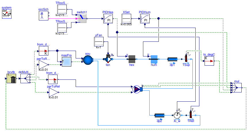
The model represents an air-based heating system with an ideal heater and an ideal humidifier
in the supply duct. The heater and humidifier are controlled with a feedback loop that
tracks the room air temperature and room air humidity. These quantities are simulated
in the EnergyPlus simulation program through the Building Controls Virtual Test Bed.
The component bouBCVTB models the boundary between the domain that models the air
system (in Modelica) and the room response (in EnergyPlus).
This model is implemented in bcvtb\examples\dymolaEPlusXY-singleZone,
where XY denotes the EnergyPlus version number.
| Type | Name | Default | Description |
|---|---|---|---|
| MassFlowRate | m_flow_nominal | 259.2*6/1.2/3600 | Nominal mass flow rate [kg/s] |
model MoistAir
  "Model with interfaces for media with moist air that will be linked to the BCVTB which models the response of the room"
  extends Modelica.Icons.Example;
  package Medium = Buildings.Media.GasesPTDecoupled.MoistAirUnsaturated;
  parameter Modelica.SIunits.MassFlowRate m_flow_nominal=
      259.2*6/1.2/3600 "Nominal mass flow rate";
  Buildings.Fluid.FixedResistances.FixedResistanceDpM dp1(
    redeclare package Medium = Medium,
    m_flow_nominal=m_flow_nominal,
    dp_nominal=200,
    from_dp=false,
    allowFlowReversal=false);
  Buildings.Fluid.Sources.Boundary_pT sou(
    nPorts=2,
    redeclare package Medium = Medium,
    use_T_in=true,
    use_X_in=true,
    p(displayUnit="Pa") = 101325,
    T=293.15);
  inner Modelica.Fluid.System system;
  Buildings.Fluid.FixedResistances.FixedResistanceDpM dp2(
    redeclare package Medium = Medium,
    m_flow_nominal=m_flow_nominal,
    dp_nominal=200,
    from_dp=false,
    allowFlowReversal=false);
  Buildings.Utilities.IO.BCVTB.MoistAirInterface bouBCVTB(
    nPorts=2,
    redeclare package Medium = Medium,
    m_flow=0,
    use_m_flow_in=false,
    m_flow_nominal=m_flow_nominal);
  Buildings.Fluid.MassExchangers.HumidifierPrescribed hum(
    m_flow_nominal=m_flow_nominal,
    dp_nominal=200,
    redeclare package Medium = Medium,
    mWat_flow_nominal=0.01*m_flow_nominal,
    from_dp=false,
    allowFlowReversal=false,
    use_T_in=false) "Humidifier";
  Buildings.Fluid.HeatExchangers.HeaterCoolerPrescribed hex(
    m_flow_nominal=m_flow_nominal,
    dp_nominal=200,
    redeclare package Medium = Medium,
    Q_flow_nominal=m_flow_nominal*50*1006,
    from_dp=false,
    allowFlowReversal=false) "Heat exchanger";
  Buildings.Fluid.Sensors.TemperatureTwoPort
                                      TRet(redeclare package Medium = Medium,
      m_flow_nominal=m_flow_nominal) "Return air temperature";
  Buildings.Fluid.Sensors.MassFractionTwoPort
                                       Xi_w(redeclare package Medium = Medium,
      m_flow_nominal=m_flow_nominal) "Measured air humidity";
  Modelica.Blocks.Sources.Constant XSet(k=0.005) "Set point for humidity";
  Modelica.Blocks.Sources.Constant TRooSetNig(k=273.15 + 16)
    "Set point for room air temperature";
  Buildings.Controls.Continuous.LimPID PIDHea(
    yMax=1,
    yMin=0,
    Td=1,
    controllerType=Modelica.Blocks.Types.SimpleController.PI,
    k=0.1,
    Ti=600) "Controller for heating";
  Buildings.Controls.Continuous.LimPID PIDHum(
    yMax=1,
    yMin=0,
    controllerType=Modelica.Blocks.Types.SimpleController.PI,
    k=20,
    Td=60,
    Ti=600) "Controller for humidifier";
  Buildings.Utilities.IO.BCVTB.BCVTB bcvtb(
    xmlFileName="socket.cfg",
    nDblRea=4,
    nDblWri=5,
    flaDblWri={1,1,1,1,1},
    uStart={0,0,0,0,20},
    activateInterface=true,
    timeStep=60);
  Modelica.Blocks.Routing.DeMultiplex4 deMultiplex2_1(
    n1=1,
    n2=1,
    n3=1,
    n4=1);
  Modelica.Blocks.Routing.Multiplex5 mul;
  Buildings.Fluid.Sensors.TemperatureTwoPort
                                      TSup(redeclare package Medium = Medium,
      m_flow_nominal=m_flow_nominal) "Supply air temperature";
  Buildings.Fluid.Movers.FlowMachine_y fan(redeclare package Medium = Medium,
        pressure(V_flow={0,m_flow_nominal/1.2},
          dp={2*400,400}),
        dynamicBalance=false);
  Modelica.Blocks.Sources.Constant yFan(k=1) "Fan control signal";
  Modelica.Blocks.Math.Gain perToRel(k=0.01) "Converts 0...100 to 0...1";
  Modelica.Blocks.Math.Gain perToRel1(
                                     k=0.01) "Converts 0...100 to 0...1";
  Buildings.Utilities.Psychrometrics.X_pTphi masFra(use_p_in=false)
    "Mass fraction";
  Buildings.Controls.SetPoints.OccupancySchedule occSch "Occupancy schedule";
  Modelica.Blocks.Logical.Switch switch1;
  Modelica.Blocks.Sources.Constant TRooSetDay(k=273.15 + 20)
    "Set point for room air temperature";
  Buildings.Utilities.IO.BCVTB.From_degC from_degC;
  Buildings.Utilities.IO.BCVTB.To_degC to_degC;
  Buildings.Utilities.IO.BCVTB.From_degC from_degC1;
equation
  connect(dp1.port_a, hum.port_b);
  connect(hex.port_b, hum.port_a);
  connect(TRet.T, PIDHea.u_m);
  connect(PIDHea.y, hex.u);
  connect(XSet.y, PIDHum.u_s);
  connect(PIDHum.y, hum.u);
  connect(bcvtb.yR, deMultiplex2_1.u);
  connect(mul.y, bcvtb.uR);
  connect(PIDHum.y, mul.u4[1]);
  connect(PIDHea.y, mul.u3[1]);
  connect(mul.u1[1], bouBCVTB.HSen_flow);
  connect(bouBCVTB.HLat_flow, mul.u2[1]);
  connect(Xi_w.X, PIDHum.u_m);
  connect(fan.port_b, hex.port_a);
  connect(fan.port_a, sou.ports[1]);
  connect(perToRel.y, bouBCVTB.phi);
  connect(deMultiplex2_1.y4[1], perToRel.u);
  connect(perToRel1.u, deMultiplex2_1.y3[1]);
  connect(masFra.phi, perToRel1.y);
  connect(masFra.X, sou.X_in);
  connect(yFan.y, fan.y);
  connect(occSch.occupied, switch1.u2);
  connect(TRooSetNig.y, switch1.u3);
  connect(TRooSetDay.y, switch1.u1);
  connect(switch1.y, PIDHea.u_s);
  connect(from_degC.Kelvin, bouBCVTB.T_in);
  connect(TSup.T, to_degC.Kelvin);
  connect(to_degC.Celsius, mul.u5[1]);
  connect(from_degC1.Kelvin, sou.T_in);
  connect(from_degC1.Celsius, deMultiplex2_1.y1[1]);
  connect(deMultiplex2_1.y2[1], from_degC.Celsius);
  connect(from_degC1.Kelvin, masFra.T);
  connect(dp2.port_b, Xi_w.port_a);
  connect(Xi_w.port_b, TRet.port_a);
  connect(TRet.port_b, sou.ports[2]);
  connect(dp1.port_b, TSup.port_a);
  connect(TSup.port_b, bouBCVTB.ports[1]);
  connect(dp2.port_a, bouBCVTB.ports[2]);
end MoistAir;
Buildings.Utilities.IO.BCVTB.Examples.TwoRooms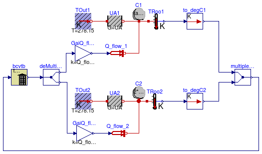
Given a control signal for two heat flow rates, Modelica simulates the thermal response of two first order systems. The two systems may represent a first order approximation of a room. The control signal for the heat flow rate is computed in the Building Controls Virtual Test Bed using a discrete time implementation of a proportional controller. Every 60 seconds, measured temperatures and control signals for the heat flow rates are exchanged between Dymola and the Building Controls Virtual Test Bed.
This model is implemented in bcvtb\examples\dymola-room.
| Type | Name | Default | Description |
|---|---|---|---|
| Time | tau | 2*3600 | Room time constant [s] |
| HeatFlowRate | Q_flow_nom | 100 | Nominal heat flow [W] |
| ThermalConductance | UA | Q_flow_nom/20 | Thermal conductance of room [W/K] |
| Temperature | TStart | 283.15 | Start temperature [K] |
model TwoRooms
  "Thermal model of two rooms that will be linked to the BCVTB which models the controls"
  extends Modelica.Icons.Example;
  parameter Modelica.SIunits.Time tau = 2*3600 "Room time constant";
  parameter Modelica.SIunits.HeatFlowRate Q_flow_nom = 100 "Nominal heat flow";
  parameter Modelica.SIunits.ThermalConductance UA = Q_flow_nom / 20
    "Thermal conductance of room";
  parameter Modelica.SIunits.Temperature TStart = 283.15 "Start temperature";
  Modelica.Thermal.HeatTransfer.Components.HeatCapacitor C1(C=tau*UA, T(start=
          TStart, fixed=true)) "Heat capacity of room";
  Modelica.Thermal.HeatTransfer.Components.ThermalConductor UA1(G=UA)
    "Heat transmission of room";
  Buildings.HeatTransfer.Sources.FixedTemperature TOut1(T=278.15)
    "Outside air temperature";
  Buildings.HeatTransfer.Sources.PrescribedHeatFlow Q_flow_1
    "Heat input into the room";
  Modelica.Blocks.Math.Gain GaiQ_flow_nom1(k=Q_flow_nom)
    "Gain for nominal heat load";
  Modelica.Thermal.HeatTransfer.Components.ThermalConductor UA2(G=UA)
    "Heat transmission of room";
  Modelica.Thermal.HeatTransfer.Components.HeatCapacitor C2(C=2*tau*UA, T(start=
          TStart, fixed=true)) "Heat capacity of room";
  Buildings.HeatTransfer.Sources.FixedTemperature TOut2(T=278.15)
    "Outside air temperature";
  Buildings.HeatTransfer.Sources.PrescribedHeatFlow Q_flow_2
    "Heat input into the room";
  Modelica.Blocks.Math.Gain GaiQ_flow_nom2(k=Q_flow_nom)
    "Gain for nominal heat load";
  Modelica.Thermal.HeatTransfer.Sensors.TemperatureSensor TRoo1
    "Room temperature";
  Modelica.Thermal.HeatTransfer.Sensors.TemperatureSensor TRoo2
    "Room temperature";
  Buildings.Utilities.IO.BCVTB.BCVTB bcvtb(
    xmlFileName="socket.cfg",
    uStart={TStart - 273.15,TStart - 273.15},
    timeStep=60,
    final nDblWri=2,
    final nDblRea=2);
  Modelica.Blocks.Routing.Multiplex2 multiplex2_1;
  Modelica.Blocks.Routing.DeMultiplex2 deMultiplex2_1;
  Buildings.Utilities.IO.BCVTB.To_degC to_degC1;
  Buildings.Utilities.IO.BCVTB.To_degC to_degC2;
equation
  connect(TOut1.port, UA1.port_a);
  connect(UA1.port_b, C1.port);
  connect(TOut2.port, UA2.port_a);
  connect(UA2.port_b, C2.port);
  connect(Q_flow_1.port, C1.port);
  connect(Q_flow_2.port, C2.port);
  connect(C1.port, TRoo1.port);
  connect(C2.port, TRoo2.port);
  connect(GaiQ_flow_nom1.y, Q_flow_1.Q_flow);
  connect(GaiQ_flow_nom2.y, Q_flow_2.Q_flow);
  connect(bcvtb.yR, deMultiplex2_1.u);
  connect(deMultiplex2_1.y1[1], GaiQ_flow_nom1.u);
  connect(deMultiplex2_1.y2[1], GaiQ_flow_nom2.u);
  connect(multiplex2_1.y, bcvtb.uR);
  connect(TRoo1.T, to_degC1.Kelvin);
  connect(TRoo2.T, to_degC2.Kelvin);
  connect(to_degC2.Celsius, multiplex2_1.u2[1]);
  connect(to_degC1.Celsius, multiplex2_1.u1[1]);
end TwoRooms;