This package contains source components, i.e., blocks which have only output signals. These blocks are used as signal generators for Real, Integer and Boolean signals.
All Real source signals (with the exception of the Constant source) have at least the following two parameters:
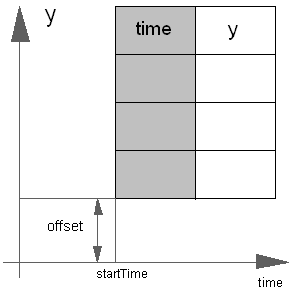
| offset | Value which is added to the signal |
| startTime | Start time of signal. For time < startTime, the output y is set to offset. |
The offset parameter is especially useful in order to shift the corresponding source, such that at initial time the system is stationary. To determine the corresponding value of offset, usually requires a trimming calculation.
Extends from Modelica.Icons.SourcesPackage (Icon for packages containing sources).
| Name | Description |
|---|---|
| Set output signal to a time varying Real expression | |
| Set output signal to a time varying Integer expression | |
| Set output signal to a time varying Boolean expression | |
| Generate actual time signal | |
| Generate constant signal of type Real | |
| Generate step signal of type Real | |
| Generate ramp signal | |
| Generate sine signal | |
| Generate exponentially damped sine signal | |
| Generate a rising and falling exponential signal | |
| Generate pulse signal of type Real | |
| Generate saw tooth signal | |
| Generate trapezoidal signal of type Real | |
| Move as fast as possible along a distance within given kinematic constraints | |
| Move as fast as possible from start to end position within given kinematic constraints with output signals q, qd=der(q), qdd=der(qd) | |
| Generate a (possibly discontinuous) signal by linear interpolation in a table | |
| Table look-up with respect to time and linear/perodic extrapolation methods (data from matrix/file) | |
| Generate constant signal of type Boolean | |
| Generate step signal of type Boolean | |
| Generate pulse signal of type Boolean | |
| Generate sample trigger signal | |
| Generate a Boolean output signal based on a vector of time instants | |
| Boolean signal source that mimis a radio button | |
| Generate constant signal of type Integer | |
| Generate step signal of type Integer | |
| Generate an Integer output signal based on a table matrix with [time, yi] values |
 Modelica.Blocks.Sources.RealExpression

The (time varying) Real output signal of this block can be defined in its parameter menu via variable y. The purpose is to support the easy definition of Real expressions in a block diagram. For example, in the y-menu the definition "if time < 1 then 0 else 1" can be given in order to define that the output signal is one, if time ≥ 1 and otherwise it is zero. Note, that "time" is a built-in variable that is always accessible and represents the "model time" and that Variable y is both a variable and a connector.
| Type | Name | Default | Description |
|---|---|---|---|
| Time varying output signal | |||
| RealOutput | y | 0.0 | Value of Real output |
| Type | Name | Description |
|---|---|---|
| Time varying output signal | ||
| output RealOutput | y | Value of Real output |
block RealExpression "Set output signal to a time varying Real expression"Modelica.Blocks.Interfaces.RealOutput y=0.0 "Value of Real output"; end RealExpression;
 Modelica.Blocks.Sources.IntegerExpression

The (time varying) Integer output signal of this block can be defined in its parameter menu via variable y. The purpose is to support the easy definition of Integer expressions in a block diagram. For example, in the y-menu the definition "if time < 1 then 0 else 1" can be given in order to define that the output signal is one, if time ≥ 1 and otherwise it is zero. Note, that "time" is a built-in variable that is always accessible and represents the "model time" and that Variable y is both a variable and a connector.
| Type | Name | Default | Description |
|---|---|---|---|
| Time varying output signal | |||
| IntegerOutput | y | 0 | Value of Integer output |
| Type | Name | Description |
|---|---|---|
| Time varying output signal | ||
| output IntegerOutput | y | Value of Integer output |
block IntegerExpression "Set output signal to a time varying Integer expression"Modelica.Blocks.Interfaces.IntegerOutput y=0 "Value of Integer output"; end IntegerExpression;
 Modelica.Blocks.Sources.BooleanExpression

The (time varying) Boolean output signal of this block can be defined in its parameter menu via variable y. The purpose is to support the easy definition of Boolean expressions in a block diagram. For example, in the y-menu the definition "time >= 1 and time <= 2" can be given in order to define that the output signal is true in the time interval 1 ≤ time ≤ 2 and otherwise it is false. Note, that "time" is a built-in variable that is always accessible and represents the "model time" and that Variable y is both a variable and a connector.
| Type | Name | Default | Description |
|---|---|---|---|
| Time varying output signal | |||
| BooleanOutput | y | false | Value of Boolean output |
| Type | Name | Description |
|---|---|---|
| Time varying output signal | ||
| output BooleanOutput | y | Value of Boolean output |
block BooleanExpression "Set output signal to a time varying Boolean expression"Modelica.Blocks.Interfaces.BooleanOutput y=false "Value of Boolean output"; end BooleanExpression;
 Modelica.Blocks.Sources.Clock
The Real output y is a clock signal:
Extends from Interfaces.SO (Single Output continuous control block).
| Type | Name | Default | Description |
|---|---|---|---|
| Time | offset | 0 | Offset of output signal [s] |
| Time | startTime | 0 | Output = offset for time < startTime [s] |
| Type | Name | Description |
|---|---|---|
| output RealOutput | y | Connector of Real output signal |
block Clock "Generate actual time signal "
  parameter Modelica.SIunits.Time offset=0 "Offset of output signal";
  parameter Modelica.SIunits.Time startTime=0
    "Output = offset for time < startTime";
  extends Interfaces.SO;

equation
  y = offset + (if time < startTime then 0 else time - startTime);
end Clock;
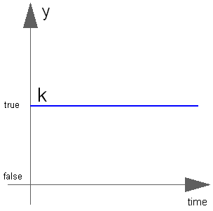
 Modelica.Blocks.Sources.Constant
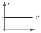
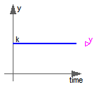
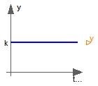
The Real output y is a constant signal:

Extends from Interfaces.SO (Single Output continuous control block).
| Type | Name | Default | Description |
|---|---|---|---|
| Real | k | Constant output value |
| Type | Name | Description |
|---|---|---|
| output RealOutput | y | Connector of Real output signal |
block Constant "Generate constant signal of type Real" parameter Real k(start=1) "Constant output value"; extends Interfaces.SO; equation y = k;end Constant;
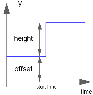
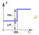
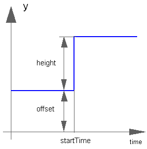
 Modelica.Blocks.Sources.Step
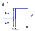
The Real output y is a step signal:
Extends from Interfaces.SignalSource (Base class for continuous signal source).
| Type | Name | Default | Description |
|---|---|---|---|
| Real | height | 1 | Height of step |
| Real | offset | 0 | Offset of output signal y |
| Time | startTime | 0 | Output y = offset for time < startTime [s] |
| Type | Name | Description |
|---|---|---|
| output RealOutput | y | Connector of Real output signal |
block Step "Generate step signal of type Real" parameter Real height=1 "Height of step"; extends Interfaces.SignalSource; equation y = offset + (if time < startTime then 0 else height);end Step;
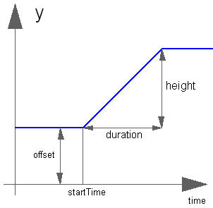
 Modelica.Blocks.Sources.Ramp
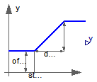
The Real output y is a ramp signal:
Extends from Interfaces.SO (Single Output continuous control block).
| Type | Name | Default | Description |
|---|---|---|---|
| Real | height | 1 | Height of ramps |
| Time | duration | Durations of ramp [s] | |
| Real | offset | 0 | Offset of output signal |
| Time | startTime | 0 | Output = offset for time < startTime [s] |
| Type | Name | Description |
|---|---|---|
| output RealOutput | y | Connector of Real output signal |
block Ramp "Generate ramp signal"
  parameter Real height=1 "Height of ramps";
  parameter Modelica.SIunits.Time duration(min=Modelica.Constants.small, start = 2)
    "Durations of ramp";
  parameter Real offset=0 "Offset of output signal";
  parameter Modelica.SIunits.Time startTime=0
    "Output = offset for time < startTime";
  extends Interfaces.SO;

equation
  y = offset + (if time < startTime then 0 else if time < (startTime +
    duration) then (time - startTime)*height/duration else height);
end Ramp;
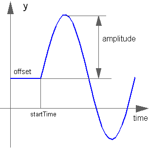
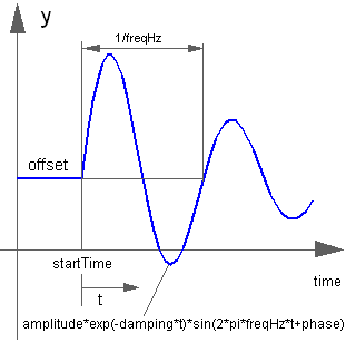
 Modelica.Blocks.Sources.Sine
The Real output y is a sine signal:
Extends from Interfaces.SO (Single Output continuous control block).
| Type | Name | Default | Description |
|---|---|---|---|
| Real | amplitude | 1 | Amplitude of sine wave |
| Frequency | freqHz | Frequency of sine wave [Hz] | |
| Angle | phase | 0 | Phase of sine wave [rad] |
| Real | offset | 0 | Offset of output signal |
| Time | startTime | 0 | Output = offset for time < startTime [s] |
| Type | Name | Description |
|---|---|---|
| output RealOutput | y | Connector of Real output signal |
block Sine "Generate sine signal"
  parameter Real amplitude=1 "Amplitude of sine wave";
  parameter SIunits.Frequency freqHz(start=1) "Frequency of sine wave";
  parameter SIunits.Angle phase=0 "Phase of sine wave";
  parameter Real offset=0 "Offset of output signal";
  parameter SIunits.Time startTime=0 "Output = offset for time < startTime";
  extends Interfaces.SO;
protected
  constant Real pi=Modelica.Constants.pi;

equation
  y = offset + (if time < startTime then 0 else amplitude*
    Modelica.Math.sin(2*pi*freqHz*(time - startTime) + phase));
end Sine;
 Modelica.Blocks.Sources.ExpSine
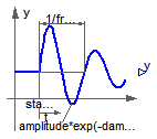
The Real output y is a sine signal with exponentially changing amplitude:
Extends from Interfaces.SO (Single Output continuous control block).
| Type | Name | Default | Description |
|---|---|---|---|
| Real | amplitude | 1 | Amplitude of sine wave |
| Frequency | freqHz | Frequency of sine wave [Hz] | |
| Angle | phase | 0 | Phase of sine wave [rad] |
| Damping | damping | Damping coefficient of sine wave [s-1] | |
| Real | offset | 0 | Offset of output signal |
| Time | startTime | 0 | Output = offset for time < startTime [s] |
| Type | Name | Description |
|---|---|---|
| output RealOutput | y | Connector of Real output signal |
block ExpSine "Generate exponentially damped sine signal"
  parameter Real amplitude=1 "Amplitude of sine wave";
  parameter SIunits.Frequency freqHz(start=2) "Frequency of sine wave";
  parameter SIunits.Angle phase=0 "Phase of sine wave";
  parameter SIunits.Damping damping(start=1) "Damping coefficient of sine wave";
  parameter Real offset=0 "Offset of output signal";
  parameter SIunits.Time startTime=0 "Output = offset for time < startTime";
  extends Interfaces.SO;
protected
  constant Real pi=Modelica.Constants.pi;

equation
  y = offset + (if time < startTime then 0 else amplitude*
    Modelica.Math.exp(-(time - startTime)*damping)*Modelica.Math.sin(2*pi*freqHz*(time - startTime) + phase));
end ExpSine;
 Modelica.Blocks.Sources.Exponentials
The Real output y is a rising exponential followed by a falling exponential signal:
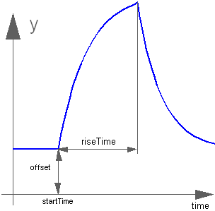
Extends from Interfaces.SO (Single Output continuous control block).
| Type | Name | Default | Description |
|---|---|---|---|
| Real | outMax | 1 | Height of output for infinite riseTime |
| Time | riseTime | Rise time [s] | |
| Time | riseTimeConst | 0.1 | Rise time constant; rising is defined as outMax*(1-exp(-riseTime/riseTimeConst)) [s] |
| Time | fallTimeConst | riseTimeConst | Fall time constant [s] |
| Real | offset | 0 | Offset of output signal |
| Time | startTime | 0 | Output = offset for time < startTime [s] |
| Type | Name | Description |
|---|---|---|
| output RealOutput | y | Connector of Real output signal |
model Exponentials "Generate a rising and falling exponential signal"

  parameter Real outMax=1 "Height of output for infinite riseTime";
  parameter SIunits.Time riseTime(min=0,start = 0.5) "Rise time";
  parameter SIunits.Time riseTimeConst(min=Modelica.Constants.small)=0.1
    "Rise time constant; rising is defined as outMax*(1-exp(-riseTime/riseTimeConst))";
  parameter SIunits.Time fallTimeConst(min=Modelica.Constants.small)=
    riseTimeConst "Fall time constant";
  parameter Real offset=0 "Offset of output signal";
  parameter SIunits.Time startTime=0 "Output = offset for time < startTime";
  extends Interfaces.SO;
protected
  Real y_riseTime;

equation
  y_riseTime = outMax*(1 - Modelica.Math.exp(-riseTime/riseTimeConst));
  y = offset + (if (time < startTime) then 0
          else if (time < (startTime + riseTime)) then outMax*(1 - Modelica.Math.exp(-(time - startTime)/riseTimeConst))
          else                                          y_riseTime*Modelica.Math.exp(-(time - startTime - riseTime)/fallTimeConst));

end Exponentials;
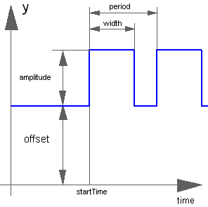
 Modelica.Blocks.Sources.Pulse
The Real output y is a pulse signal:
Extends from Modelica.Blocks.Interfaces.SO (Single Output continuous control block).
| Type | Name | Default | Description |
|---|---|---|---|
| Real | amplitude | 1 | Amplitude of pulse |
| Real | width | 50 | Width of pulse in % of period |
| Time | period | Time for one period [s] | |
| Integer | nperiod | -1 | Number of periods (< 0 means infinite number of periods) |
| Real | offset | 0 | Offset of output signals |
| Time | startTime | 0 | Output = offset for time < startTime [s] |
| Type | Name | Description |
|---|---|---|
| output RealOutput | y | Connector of Real output signal |
block Pulse "Generate pulse signal of type Real"
  parameter Real amplitude=1 "Amplitude of pulse";
  parameter Real width(
    final min=Modelica.Constants.small,
    final max=100) = 50 "Width of pulse in % of period";
  parameter Modelica.SIunits.Time period(final min=Modelica.Constants.small,start=1)
    "Time for one period";
  parameter Integer nperiod=-1
    "Number of periods (< 0 means infinite number of periods)";
  parameter Real offset=0 "Offset of output signals";
  parameter Modelica.SIunits.Time startTime=0
    "Output = offset for time < startTime";
  extends Modelica.Blocks.Interfaces.SO;
protected
  Modelica.SIunits.Time T_width = period*width/100;
  Modelica.SIunits.Time T_start "Start time of current period";
  Integer count "Period count";
initial algorithm
  count := integer((time - startTime)/period);
  T_start := startTime + count*period;
equation
  when integer((time - startTime)/period)>pre(count) then
    count = pre(count)+1;
    T_start = time;
  end when;
  y = offset + (if (time<startTime or nperiod==0 or (nperiod>0 and count>=nperiod)) then 0
           else if  time<T_start + T_width then amplitude else 0);
end Pulse;
 Modelica.Blocks.Sources.SawTooth
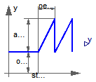
The Real output y is a saw tooth signal:

Extends from Interfaces.SO (Single Output continuous control block).
| Type | Name | Default | Description |
|---|---|---|---|
| Real | amplitude | 1 | Amplitude of saw tooth |
| Time | period | Time for one period [s] | |
| Integer | nperiod | -1 | Number of periods (< 0 means infinite number of periods) |
| Real | offset | 0 | Offset of output signals |
| Time | startTime | 0 | Output = offset for time < startTime [s] |
| Type | Name | Description |
|---|---|---|
| output RealOutput | y | Connector of Real output signal |
block SawTooth "Generate saw tooth signal"
  parameter Real amplitude=1 "Amplitude of saw tooth";
  parameter SIunits.Time period(final min=Modelica.Constants.small,start = 1)
    "Time for one period";
  parameter Integer nperiod=-1
    "Number of periods (< 0 means infinite number of periods)";
  parameter Real offset=0 "Offset of output signals";
  parameter SIunits.Time startTime=0 "Output = offset for time < startTime";
  extends Interfaces.SO;
protected
  SIunits.Time T_start(final start=startTime) "Start time of current period";
  Integer count "Period count";
initial algorithm
  count := integer((time - startTime)/period);
  T_start := startTime + count*period;
equation
  when integer((time - startTime)/period)>pre(count) then
    count = pre(count)+1;
    T_start = time;
  end when;
  y = offset + (if (time<startTime or nperiod==0 or (nperiod>0 and count>=nperiod)) then 0
               else amplitude*(time - T_start)/period);
end SawTooth;
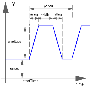
 Modelica.Blocks.Sources.Trapezoid
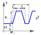
The Real output y is a trapezoid signal:
Extends from Interfaces.SO (Single Output continuous control block).
| Type | Name | Default | Description |
|---|---|---|---|
| Real | amplitude | 1 | Amplitude of trapezoid |
| Time | rising | 0 | Rising duration of trapezoid [s] |
| Time | width | 0.5 | Width duration of trapezoid [s] |
| Time | falling | 0 | Falling duration of trapezoid [s] |
| Time | period | Time for one period [s] | |
| Integer | nperiod | -1 | Number of periods (< 0 means infinite number of periods) |
| Real | offset | 0 | Offset of output signal |
| Time | startTime | 0 | Output = offset for time < startTime [s] |
| Type | Name | Description |
|---|---|---|
| output RealOutput | y | Connector of Real output signal |
block Trapezoid "Generate trapezoidal signal of type Real"
  parameter Real amplitude=1 "Amplitude of trapezoid";
  parameter SIunits.Time rising(final min=0) = 0 "Rising duration of trapezoid";
  parameter SIunits.Time width(final min=0) = 0.5 "Width duration of trapezoid";
  parameter SIunits.Time falling(final min=0) = 0
    "Falling duration of trapezoid";
  parameter SIunits.Time period(final min=Modelica.Constants.small, start= 1)
    "Time for one period";
  parameter Integer nperiod=-1
    "Number of periods (< 0 means infinite number of periods)";
  parameter Real offset=0 "Offset of output signal";
  parameter SIunits.Time startTime=0 "Output = offset for time < startTime";
  extends Interfaces.SO;
protected
  parameter SIunits.Time T_rising=rising
    "End time of rising phase within one period";
  parameter SIunits.Time T_width=T_rising + width
    "End time of width phase within one period";
  parameter SIunits.Time T_falling=T_width + falling
    "End time of falling phase within one period";
  SIunits.Time T_start "Start time of current period";
  Integer count "Period count";
initial algorithm
  count := integer((time - startTime)/period);
  T_start := startTime + count*period;
equation
  when integer((time - startTime)/period)>pre(count) then
    count = pre(count)+1;
    T_start = time;
  end when;
  y = offset + (if (time<startTime or nperiod==0 or (nperiod>0 and count>=nperiod)) then 0
           else if (time < T_start + T_rising)  then amplitude*(time - T_start)/rising
           else if (time < T_start + T_width)   then amplitude
           else if (time < T_start + T_falling) then amplitude*(T_start + T_falling - time)/falling
           else                                 0);
end Trapezoid;
 Modelica.Blocks.Sources.KinematicPTP
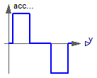
The goal is to move as fast as possible along a distance deltaq under given kinematical constraints. The distance can be a positional or angular range. In robotics such a movement is called PTP (Point-To-Point). This source block generates the acceleration qdd of this signal as output:
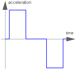
After integrating the output two times, the position q is obtained. The signal is constructed in such a way that it is not possible to move faster, given the maximally allowed velocity qd_max and the maximally allowed acceleration qdd_max.
If several distances are given (vector deltaq has more than 1 element), an acceleration output vector is constructed such that all signals are in the same periods in the acceleration, constant velocity and deceleration phase. This means that only one of the signals is at its limits whereas the others are sychnronized in such a way that the end point is reached at the same time instant.
This element is useful to generate a reference signal for a controller which controls a drive train or in combination with model Modelica.Mechanics.Rotational.Accelerate to drive a flange according to a given acceleration.
Extends from Interfaces.MO (Multiple Output continuous control block).
| Type | Name | Default | Description |
|---|---|---|---|
| Real | deltaq[:] | Distance to move | |
| Real | qd_max[:] | Maximum velocities der(q) | |
| Real | qdd_max[:] | Maximum accelerations der(qd) | |
| Time | startTime | 0 | Time instant at which movement starts [s] |
| Integer | nout | max([size(deltaq, 1); size(q... | Number of outputs |
| Type | Name | Description |
|---|---|---|
| output RealOutput | y[nout] | Connector of Real output signals |
block KinematicPTP
  "Move as fast as possible along a distance within given kinematic constraints"

  parameter Real deltaq[:] "Distance to move";
  parameter Real qd_max[:](each final min=Modelica.Constants.small)
    "Maximum velocities der(q)";
  parameter Real qdd_max[:](each final min=Modelica.Constants.small)
    "Maximum accelerations der(qd)";
  parameter SIunits.Time startTime=0 "Time instant at which movement starts";

  extends Interfaces.MO(final nout=max([size(deltaq, 1); size(qd_max, 1);
         size(qdd_max, 1)]));

protected
  parameter Real p_deltaq[nout]=(if size(deltaq, 1) == 1 then ones(nout)*
      deltaq[1] else deltaq);
  parameter Real p_qd_max[nout]=(if size(qd_max, 1) == 1 then ones(nout)*
      qd_max[1] else qd_max);
  parameter Real p_qdd_max[nout]=(if size(qdd_max, 1) == 1 then ones(nout)
      *qdd_max[1] else qdd_max);
  Real sd_max;
  Real sdd_max;
  Real sdd;
  Real aux1[nout];
  Real aux2[nout];
  SIunits.Time Ta1;
  SIunits.Time Ta2;
  SIunits.Time Tv;
  SIunits.Time Te;
  Boolean noWphase;

equation
  for i in 1:nout loop
    aux1[i] = p_deltaq[i]/p_qd_max[i];
    aux2[i] = p_deltaq[i]/p_qdd_max[i];
  end for;
  sd_max = 1/max(abs(aux1));
  sdd_max = 1/max(abs(aux2));

  Ta1 = sqrt(1/sdd_max);
  Ta2 = sd_max/sdd_max;
  noWphase = Ta2 >= Ta1;
  Tv = if noWphase then Ta1 else 1/sd_max;
  Te = if noWphase then Ta1 + Ta1 else Tv + Ta2;

  // path-acceleration
  sdd = if time < startTime then 0 else ((if noWphase then (if time < Ta1
     + startTime then sdd_max else (if time < Te + startTime then -
    sdd_max else 0)) else (if time < Ta2 + startTime then sdd_max else (
    if time < Tv + startTime then 0 else (if time < Te + startTime then -
    sdd_max else 0)))));

  // acceleration
  y = p_deltaq*sdd;
end KinematicPTP;
 Modelica.Blocks.Sources.KinematicPTP2
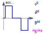
The goal is to move as fast as possible from start position q_begin to end position q_end under given kinematical constraints. The positions can be translational or rotational definitions (i.e., q_begin/q_end is given). In robotics such a movement is called PTP (Point-To-Point). This source block generates the position q(t), the speed qd(t) = der(q), and the acceleration qdd = der(qd) as output. The signals are constructed in such a way that it is not possible to move faster, given the maximally allowed velocity qd_max and the maximally allowed acceleration qdd_max:

If vectors q_begin/q_end have more than 1 element, the output vectors are constructed such that all signals are in the same periods in the acceleration, constant velocity and deceleration phase. This means that only one of the signals is at its limits whereas the others are sychnronized in such a way that the end point is reached at the same time instant.
This element is useful to generate a reference signal for a controller which controls, e.g., a drive train, or to drive a flange according to a given acceleration.
Extends from Modelica.Blocks.Interfaces.BlockIcon (Basic graphical layout of input/output block).
| Type | Name | Default | Description |
|---|---|---|---|
| Real | q_begin[:] | {0} | Start position |
| Real | q_end[:] | End position | |
| Real | qd_max[:] | Maximum velocities der(q) | |
| Real | qdd_max[:] | Maximum accelerations der(qd) | |
| Time | startTime | 0 | Time instant at which movement starts [s] |
| Type | Name | Description |
|---|---|---|
| output RealOutput | q[nout] | Reference position of path planning |
| output RealOutput | qd[nout] | Reference speed of path planning |
| output RealOutput | qdd[nout] | Reference acceleration of path planning |
| output BooleanOutput | moving[nout] | = true, if end position not yet reached; = false, if end position reached or axis is completely at rest |
block KinematicPTP2
"Move as fast as possible from start to end position within given kinematic constraints with output signals q, qd=der(q), qdd=der(qd)"
import SI = Modelica.SIunits;
parameter Real q_begin[:] = {0} "Start position";
parameter Real q_end[:] "End position";
parameter Real qd_max[:](each final min=Modelica.Constants.small)
"Maximum velocities der(q)";
parameter Real qdd_max[:](each final min=Modelica.Constants.small)
"Maximum accelerations der(qd)";
parameter Modelica.SIunits.Time startTime=0
"Time instant at which movement starts";
extends Modelica.Blocks.Interfaces.BlockIcon;
final parameter Integer nout=max([size(q_begin, 1); size(q_end, 1); size(
qd_max, 1); size(qdd_max, 1)])
"Number of output signals (= dimension of q, qd, qdd, moving)";
output Modelica.SIunits.Time endTime "Time instant at which movement stops";
Modelica.Blocks.Interfaces.RealOutput q[nout]
"Reference position of path planning";
Modelica.Blocks.Interfaces.RealOutput qd[nout]
"Reference speed of path planning";
Modelica.Blocks.Interfaces.RealOutput qdd[nout]
"Reference acceleration of path planning";
Modelica.Blocks.Interfaces.BooleanOutput moving[nout]
"= true, if end position not yet reached; = false, if end position reached or axis is completely at rest";
protected
parameter Real p_q_begin[nout]=(if size(q_begin, 1) == 1 then ones(nout)*
q_begin[1] else q_begin);
parameter Real p_q_end[nout]=(if size(q_end, 1) == 1 then ones(nout)*
q_end[1] else q_end);
parameter Real p_qd_max[nout]=(if size(qd_max, 1) == 1 then ones(nout)*
qd_max[1] else qd_max);
parameter Real p_qdd_max[nout]=(if size(qdd_max, 1) == 1 then ones(nout)*
qdd_max[1] else qdd_max);
parameter Real p_deltaq[nout]=p_q_end - p_q_begin;
constant Real eps=10*Modelica.Constants.eps;
Boolean motion_ref;
Real sd_max_inv;
Real sdd_max_inv;
Real sd_max;
Real sdd_max;
Real sdd;
Real aux1[nout];
Real aux2[nout];
SI.Time Ta1;
SI.Time Ta2;
SI.Time Tv;
SI.Time Te;
Boolean noWphase;
SI.Time Ta1s;
SI.Time Ta2s;
SI.Time Tvs;
SI.Time Tes;
Real sd_max2;
Real s1;
Real s2;
Real s3;
Real s;
Real sd;
Real r_s;
Real r_sd;
Real r_sdd;
function position
annotation(derivative=position_der);
input Real q_qd_qdd[3] "Required values for position, speed, acceleration";
input Real dummy
"Just to have one input signal that should be differentiated to avoid possible problems in the Modelica tool (is not used)";
output Real q;
algorithm
q :=q_qd_qdd[1];
end position ;
function position_der
annotation(derivative=position_der2);
input Real q_qd_qdd[3] "Required values for position, speed, acceleration";
input Real dummy
"Just to have one input signal that should be differentiated to avoid possible problems in the Modelica tool (is not used)";
input Real dummy_der;
output Real qd;
algorithm
qd :=q_qd_qdd[2];
end position_der ;
function position_der2
input Real q_qd_qdd[3] "Required values for position, speed, acceleration";
input Real dummy
"Just to have one input signal that should be differentiated to avoid possible problems in the Modelica tool (is not used)";
input Real dummy_der;
input Real dummy_der2;
output Real qdd;
algorithm
qdd :=q_qd_qdd[3];
end position_der2 ;
equation
for i in 1:nout loop
aux1[i] = p_deltaq[i]/p_qd_max[i];
aux2[i] = p_deltaq[i]/p_qdd_max[i];
end for;
sd_max_inv = max(abs(aux1));
sdd_max_inv = max(abs(aux2));
if sd_max_inv <= eps or sdd_max_inv <= eps then
sd_max = 0;
sdd_max = 0;
Ta1 = 0;
Ta2 = 0;
noWphase = false;
Tv = 0;
Te = 0;
Ta1s = 0;
Ta2s = 0;
Tvs = 0;
Tes = 0;
sd_max2 = 0;
s1 = 0;
s2 = 0;
s3 = 0;
r_sdd = 0;
r_sd = 0;
r_s = 0;
else
sd_max = 1/max(abs(aux1));
sdd_max = 1/max(abs(aux2));
Ta1 = sqrt(1/sdd_max);
Ta2 = sd_max/sdd_max;
noWphase = Ta2 >= Ta1;
Tv = if noWphase then Ta1 else 1/sd_max;
Te = if noWphase then Ta1 + Ta1 else Tv + Ta2;
Ta1s = Ta1 + startTime;
Ta2s = Ta2 + startTime;
Tvs = Tv + startTime;
Tes = Te + startTime;
sd_max2 = sdd_max*Ta1;
s1 = sdd_max*(if noWphase then Ta1*Ta1 else Ta2*Ta2)/2;
s2 = s1 + (if noWphase then sd_max2*(Te - Ta1) - (sdd_max/2)*(Te - Ta1)
^2 else sd_max*(Tv - Ta2));
s3 = s2 + sd_max*(Te - Tv) - (sdd_max/2)*(Te - Tv)*(Te - Tv);
if time < startTime then
r_sdd = 0;
r_sd = 0;
r_s = 0;
elseif noWphase then
if time < Ta1s then
r_sdd = sdd_max;
r_sd = sdd_max*(time - startTime);
r_s = (sdd_max/2)*(time - startTime)*(time - startTime);
elseif time < Tes then
r_sdd = -sdd_max;
r_sd = sd_max2 - sdd_max*(time - Ta1s);
r_s = s1 + sd_max2*(time - Ta1s) - (sdd_max/2)*(time - Ta1s)*(time
- Ta1s);
else
r_sdd = 0;
r_sd = 0;
r_s = s2;
end if;
elseif time < Ta2s then
r_sdd = sdd_max;
r_sd = sdd_max*(time - startTime);
r_s = (sdd_max/2)*(time - startTime)*(time - startTime);
elseif time < Tvs then
r_sdd = 0;
r_sd = sd_max;
r_s = s1 + sd_max*(time - Ta2s);
elseif time < Tes then
r_sdd = -sdd_max;
r_sd = sd_max - sdd_max*(time - Tvs);
r_s = s2 + sd_max*(time - Tvs) - (sdd_max/2)*(time - Tvs)*(time - Tvs);
else
r_sdd = 0;
r_sd = 0;
r_s = s3;
end if;
end if;
// acceleration
qdd = p_deltaq*sdd;
qd = p_deltaq*sd;
q = p_q_begin + p_deltaq*s;
endTime = Tes;
s = position({r_s, r_sd, r_sdd}, time);
sd = der(s);
sdd = der(sd);
// report when axis is moving
motion_ref = time <= endTime;
for i in 1:nout loop
moving[i] = if abs(q_begin[i] - q_end[i]) > eps then motion_ref else false;
end for;
end KinematicPTP2;
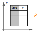
 Modelica.Blocks.Sources.TimeTable
This block generates an output signal by linear interpolation in a table. The time points and function values are stored in a matrix table[i,j], where the first column table[:,1] contains the time points and the second column contains the data to be interpolated. The table interpolation has the following proporties:
Example:
   table = [0  0
            1  0
            1  1
            2  4
            3  9
            4 16]
If, e.g., time = 1.0, the output y =  0.0 (before event), 1.0 (after event)
    e.g., time = 1.5, the output y =  2.5,
    e.g., time = 2.0, the output y =  4.0,
    e.g., time = 5.0, the output y = 23.0 (i.e., extrapolation).
Extends from Interfaces.SO (Single Output continuous control block).
| Type | Name | Default | Description |
|---|---|---|---|
| Real | table[:, 2] | Table matrix (time = first column; e.g., table=[0, 0; 1, 1; 2, 4]) | |
| Real | offset | 0 | Offset of output signal |
| Time | startTime | 0 | Output = offset for time < startTime [s] |
| Type | Name | Description |
|---|---|---|
| output RealOutput | y | Connector of Real output signal |
block TimeTable
"Generate a (possibly discontinuous) signal by linear interpolation in a table"
parameter Real table[:, 2]
"Table matrix (time = first column; e.g., table=[0, 0; 1, 1; 2, 4])";
parameter Real offset=0 "Offset of output signal";
parameter SIunits.Time startTime=0 "Output = offset for time < startTime";
extends Interfaces.SO;
protected
Real a "Interpolation coefficients a of actual interval (y=a*x+b)";
Real b "Interpolation coefficients b of actual interval (y=a*x+b)";
Integer last(start=1) "Last used lower grid index";
SIunits.Time nextEvent(start=0, fixed=true) "Next event instant";
function getInterpolationCoefficients
"Determine interpolation coefficients and next time event"
input Real table[:, 2] "Table for interpolation";
input Real offset "y-offset";
input Real startTime "time-offset";
input Real t "Actual time instant";
input Integer last "Last used lower grid index";
input Real TimeEps "Relative epsilon to check for identical time instants";
output Real a "Interpolation coefficients a (y=a*x + b)";
output Real b "Interpolation coefficients b (y=a*x + b)";
output Real nextEvent "Next event instant";
output Integer next "New lower grid index";
protected
Integer columns=2 "Column to be interpolated";
Integer ncol=2 "Number of columns to be interpolated";
Integer nrow=size(table, 1) "Number of table rows";
Integer next0;
Real tp;
Real dt;
algorithm
next := last;
nextEvent := t - TimeEps*abs(t);
// in case there are no more time events
tp := t + TimeEps*abs(t) - startTime;
if tp < 0.0 then
// First event not yet reached
nextEvent := startTime;
a := 0;
b := offset;
elseif nrow < 2 then
// Special action if table has only one row
a := 0;
b := offset + table[1, columns];
else
// Find next time event instant. Note, that two consecutive time instants
// in the table may be identical due to a discontinuous point.
while next < nrow and tp >= table[next, 1] loop
next := next + 1;
end while;
// Define next time event, if last table entry not reached
if next < nrow then
nextEvent := startTime + table[next, 1];
end if;
// Determine interpolation coefficients
next0 := next - 1;
dt := table[next, 1] - table[next0, 1];
if dt <= TimeEps*abs(table[next, 1]) then
// Interpolation interval is not big enough, use "next" value
a := 0;
b := offset + table[next, columns];
else
a := (table[next, columns] - table[next0, columns])/dt;
b := offset + table[next0, columns] - a*table[next0, 1];
end if;
end if;
// Take into account startTime "a*(time - startTime) + b"
b := b - a*startTime;
end getInterpolationCoefficients ;
algorithm
when {time >= pre(nextEvent),initial()} then
(a,b,nextEvent,last) := getInterpolationCoefficients(table, offset,
startTime, time, last, 100*Modelica.Constants.eps);
end when;
equation
y = a*time + b;
end TimeTable;
 Modelica.Blocks.Sources.CombiTimeTable
This block generates an output signal y[:] by linear interpolation in a table. The time points and function values are stored in a matrix table[i,j], where the first column table[:,1] contains the time points and the other columns contain the data to be interpolated.
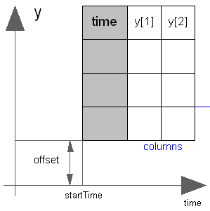
Via parameter columns it can be defined which columns of the table are interpolated. If, e.g., columns={2,4}, it is assumed that 2 output signals are present and that the first output is computed by interpolation of column 2 and the second output is computed by interpolation of column 4 of the table matrix. The table interpolation has the following properties:
  extrapolation = 0: hold the first or last value of the table,
                     if outside of the range.
                = 1: extrapolate through the last or first two
                     points of the table.
                = 2: periodically repeat the table data
                     (periodical function).
  smoothness = 0: linear interpolation
             = 1: smooth interpolation with Akima Splines such
                  that der(y) is continuous.
Example:
   table = [0  0
            1  0
            1  1
            2  4
            3  9
            4 16]; extrapolation = 1 (default)
If, e.g., time = 1.0, the output y =  0.0 (before event), 1.0 (after event)
    e.g., time = 1.5, the output y =  2.5,
    e.g., time = 2.0, the output y =  4.0,
    e.g., time = 5.0, the output y = 23.0 (i.e., extrapolation via last 2 points).
The table matrix can be defined in the following ways:
   tableName is "NoName" or has only blanks,
   fileName  is "NoName" or has only blanks.
save tables.mat tab1 tab2 tab3 -V4when the three tables tab1, tab2, tab3 should be used from the model.
Table definition methods (1) and (3) do not allocate dynamic memory, and do not access files, whereas method (2) does. Therefore (1) and (3) are suited for hardware-in-the-loop simulation (e.g., with dSpace hardware). When the constant "NO_FILE" is defined in "usertab.c", all parts of the source code of method (2) are removed by the C-preprocessor, such that no dynamic memory allocation and no access to files takes place.
If tables are read from an ASCII-file, the file need to have the following structure ("-----" is not part of the file content):
-----------------------------------------------------
#1
double tab1(6,2)   # comment line
  0   0
  1   0
  1   1
  2   4
  3   9
  4  16
double tab2(6,2)   # another comment line
  0   0
  2   0
  2   2
  4   8
  6  18
  8  32
-----------------------------------------------------
Note, that the first two characters in the file need to be "#1". Afterwards, the corresponding matrix has to be declared with type, name and actual dimensions. Finally, in successive rows of the file, the elements of the matrix have to be given. Several matrices may be defined one after another.
Extends from Modelica.Blocks.Interfaces.MO (Multiple Output continuous control block).
| Type | Name | Default | Description |
|---|---|---|---|
| Integer | nout | max([size(columns, 1); size(... | Number of outputs |
| table data definition | |||
| Boolean | tableOnFile | false | = true, if table is defined on file or in function usertab |
| Real | table[:, :] | fill(0.0, 0, 2) | Table matrix (time = first column; e.g., table=[0,2]) |
| String | tableName | "NoName" | Table name on file or in function usertab (see docu) |
| String | fileName | "NoName" | File where matrix is stored |
| table data interpretation | |||
| Integer | columns[:] | 2:size(table, 2) | Columns of table to be interpolated |
| Smoothness | smoothness | Modelica.Blocks.Types.Smooth... | Smoothness of table interpolation |
| Extrapolation | extrapolation | Modelica.Blocks.Types.Extrap... | Extrapolation of data outside the definition range |
| Real | offset[:] | {0} | Offsets of output signals |
| Time | startTime | 0 | Output = offset for time < startTime [s] |
| Type | Name | Description |
|---|---|---|
| output RealOutput | y[nout] | Connector of Real output signals |
model CombiTimeTable
"Table look-up with respect to time and linear/perodic extrapolation methods (data from matrix/file)"
parameter Boolean tableOnFile=false
"= true, if table is defined on file or in function usertab";
parameter Real table[:, :] = fill(0.0,0,2)
"Table matrix (time = first column; e.g., table=[0,2])";
parameter String tableName="NoName"
"Table name on file or in function usertab (see docu)";
parameter String fileName="NoName" "File where matrix is stored";
parameter Integer columns[:]=2:size(table, 2)
"Columns of table to be interpolated";
parameter Modelica.Blocks.Types.Smoothness smoothness=Modelica.Blocks.Types.Smoothness.LinearSegments
"Smoothness of table interpolation";
parameter Modelica.Blocks.Types.Extrapolation extrapolation=Modelica.Blocks.Types.Extrapolation.LastTwoPoints
"Extrapolation of data outside the definition range";
parameter Real offset[:]={0} "Offsets of output signals";
parameter Modelica.SIunits.Time startTime=0
"Output = offset for time < startTime";
extends Modelica.Blocks.Interfaces.MO(final nout=max([size(columns, 1); size(offset, 1)]));
final parameter Real t_min(fixed=false)
"Minimum abscissa value defined in table";
final parameter Real t_max(fixed=false)
"Maximum abscissa value defined in table";
protected
final parameter Real p_offset[nout]=(if size(offset, 1) == 1 then ones(nout)
*offset[1] else offset);
Integer tableID;
function tableTimeInit
"Initialize 1-dim. table where first column is time (for details see: Modelica/Resources/C-Sources/ModelicaTables.h)"
input String tableName;
input String fileName;
input Real table[ :, :];
input Real startTime;
input Modelica.Blocks.Types.Smoothness smoothness;
input Modelica.Blocks.Types.Extrapolation extrapolation;
output Integer tableID;
external "C" tableID= ModelicaTables_CombiTimeTable_init(
tableName, fileName, table, size(table, 1), size(table, 2),
startTime, smoothness, extrapolation);
end tableTimeInit ;
function tableTimeIpo
"Interpolate 1-dim. table where first column is time (for details see: Modelica/Resources/C-Sources/ModelicaTables.h)"
input Integer tableID;
input Integer icol;
input Real timeIn;
output Real value;
external "C" value =
ModelicaTables_CombiTimeTable_interpolate(tableID, icol, timeIn);
end tableTimeIpo ;
function tableTimeTmin
"Return minimum time value of 1-dim. table where first column is time (for details see: Modelica/Resources/C-Sources/ModelicaTables.h)"
input Integer tableID;
output Real Tmin "minimum time value in table";
external "C" Tmin =
ModelicaTables_CombiTimeTable_minimumTime(tableID);
end tableTimeTmin ;
function tableTimeTmax
"Return maximum time value of 1-dim. table where first column is time (for details see: Modelica/Resources/C-Sources/ModelicaTables.h)"
input Integer tableID;
output Real Tmax "maximum time value in table";
external "C" Tmax =
ModelicaTables_CombiTimeTable_maximumTime(tableID);
end tableTimeTmax ;
equation
if tableOnFile then
assert(tableName<>"NoName", "tableOnFile = true and no table name given");
end if;
if not tableOnFile then
assert(size(table,1) > 0 and size(table,2) > 0, "tableOnFile = false and parameter table is an empty matrix");
end if;
for i in 1:nout loop
y[i] = p_offset[i] + tableTimeIpo(tableID, columns[i], time);
end for;
when initial() then
tableID=tableTimeInit((if not tableOnFile then "NoName" else tableName),
(if not tableOnFile then "NoName" else fileName), table,
startTime, smoothness, extrapolation);
end when;
initial equation
t_min=tableTimeTmin(tableID);
t_max=tableTimeTmax(tableID);
end CombiTimeTable;
 Modelica.Blocks.Sources.BooleanConstant
The Boolean output y is a constant signal:
Extends from Interfaces.partialBooleanSource (Partial source block (has 1 output Boolean signal and an appropriate default icon)).
| Type | Name | Default | Description |
|---|---|---|---|
| Boolean | k | true | Constant output value |
| Type | Name | Description |
|---|---|---|
| output BooleanOutput | y | Connector of Boolean output signal |
block BooleanConstant "Generate constant signal of type Boolean" parameter Boolean k=true "Constant output value"; extends Interfaces.partialBooleanSource; equation y = k;end BooleanConstant;
 Modelica.Blocks.Sources.BooleanStep
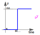
The Boolean output y is a step signal:

Extends from Interfaces.partialBooleanSource (Partial source block (has 1 output Boolean signal and an appropriate default icon)).
| Type | Name | Default | Description |
|---|---|---|---|
| Time | startTime | 0 | Time instant of step start [s] |
| Boolean | startValue | false | Output before startTime |
| Type | Name | Description |
|---|---|---|
| output BooleanOutput | y | Connector of Boolean output signal |
block BooleanStep "Generate step signal of type Boolean" parameter Modelica.SIunits.Time startTime=0 "Time instant of step start"; parameter Boolean startValue = false "Output before startTime"; extends Interfaces.partialBooleanSource; equation y = if time >= startTime then not startValue else startValue;end BooleanStep;
 Modelica.Blocks.Sources.BooleanPulse
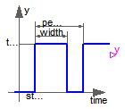
The Boolean output y is a pulse signal:
Extends from Modelica.Blocks.Interfaces.partialBooleanSource (Partial source block (has 1 output Boolean signal and an appropriate default icon)).
| Type | Name | Default | Description |
|---|---|---|---|
| Real | width | 50 | Width of pulse in % of period |
| Time | period | Time for one period [s] | |
| Time | startTime | 0 | Time instant of first pulse [s] |
| Type | Name | Description |
|---|---|---|
| output BooleanOutput | y | Connector of Boolean output signal |
block BooleanPulse "Generate pulse signal of type Boolean"

  parameter Real width(
    final min=Modelica.Constants.small,
    final max=100) = 50 "Width of pulse in % of period";
  parameter Modelica.SIunits.Time period(final min=Modelica.Constants.small,start=1)
    "Time for one period";
  parameter Modelica.SIunits.Time startTime=0 "Time instant of first pulse";
  extends Modelica.Blocks.Interfaces.partialBooleanSource;

protected
  parameter Modelica.SIunits.Time Twidth=period*width/100 "width of one pulse";
  discrete Modelica.SIunits.Time pulsStart "Start time of pulse";
initial equation
  pulsStart = startTime;
equation
    when sample(startTime, period) then
      pulsStart = time;
    end when;
    y = time >= pulsStart and time < pulsStart + Twidth;
end BooleanPulse;
 Modelica.Blocks.Sources.SampleTrigger
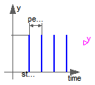
The Boolean output y is a trigger signal where the output y is only true at sample times (defined by parameter period) and is otherwise false.
Extends from Interfaces.partialBooleanSource (Partial source block (has 1 output Boolean signal and an appropriate default icon)).
| Type | Name | Default | Description |
|---|---|---|---|
| Time | period | Sample period [s] | |
| Time | startTime | 0 | Time instant of first sample trigger [s] |
| Type | Name | Description |
|---|---|---|
| output BooleanOutput | y | Connector of Boolean output signal |
block SampleTrigger "Generate sample trigger signal"
  parameter Modelica.SIunits.Time period(final min=Modelica.Constants.small,start=0.01)
    "Sample period";
  parameter Modelica.SIunits.Time startTime=0
    "Time instant of first sample trigger";
  extends Interfaces.partialBooleanSource;

equation
  y = sample(startTime, period);
end SampleTrigger;
 Modelica.Blocks.Sources.BooleanTable
The Boolean output y is a signal defined by parameter vector table. In the vector time points are stored. At every time point, the output y changes its value to the negated value of the previous one.
Extends from Interfaces.partialBooleanSource (Partial source block (has 1 output Boolean signal and an appropriate default icon)).
| Type | Name | Default | Description |
|---|---|---|---|
| Boolean | startValue | false | Start value of y. At time = table[1], y changes to 'not startValue' |
| Time | table[:] | Vector of time points. At every time point, the output y gets its opposite value (e.g., table={0,1}) [s] |
| Type | Name | Description |
|---|---|---|
| output BooleanOutput | y | Connector of Boolean output signal |
block BooleanTable
"Generate a Boolean output signal based on a vector of time instants"
parameter Boolean startValue = false
"Start value of y. At time = table[1], y changes to 'not startValue'";
parameter Modelica.SIunits.Time table[:]
"Vector of time points. At every time point, the output y gets its opposite value (e.g., table={0,1})";
extends Interfaces.partialBooleanSource;
protected
function getFirstIndex "Get first index of table and check table"
input Real table[:] "Vector of time instants";
input Modelica.SIunits.Time simulationStartTime "Simulation start time";
input Boolean startValue "Value of y for y < table[1]";
output Integer index "First index to be used";
output Modelica.SIunits.Time nextTime "Time instant of first event";
output Boolean y "Value of y at simulationStartTime";
protected
Modelica.SIunits.Time t_last;
Integer j;
Integer n=size(table,1) "Number of table points";
algorithm
if size(table,1) == 0 then
index :=0;
nextTime :=-Modelica.Constants.inf;
y :=startValue;
elseif size(table,1) == 1 then
index :=1;
if table[1] > simulationStartTime then
nextTime :=table[1];
y :=startValue;
else
nextTime :=simulationStartTime;
y :=startValue;
end if;
else
// Check whether time values are strict monotonically increasing
t_last :=table[1];
for i in 2:n loop
assert(table[i] > t_last,
"Time values of table not strict monotonically increasing: table[" +
String(i-1) + "] = " + String(table[i-1]) + "table[" + String(i) +
"] = " + String(table[i]));
end for;
// Determine first index in table
j := 1;
y := startValue;
while j < n and table[j] <= simulationStartTime loop
y :=not y;
j := j + 1;
end while;
if j == 1 then
nextTime := table[1];
y := startValue;
elseif j == n and table[n] <= simulationStartTime then
nextTime := simulationStartTime - 1;
y :=not y;
else
nextTime := table[j];
end if;
index := j;
end if;
end getFirstIndex ;
parameter Integer n = size(table,1) "Number of table points";
Modelica.SIunits.Time nextTime;
Integer index "Index of actual table entry";
initial algorithm
(index, nextTime, y) :=getFirstIndex(table, time, startValue);
algorithm
when time >= pre(nextTime) and n > 0 then
if index < n then
index := index + 1;
nextTime := table[index];
y :=not y;
elseif index == n then
index := index + 1;
y :=not y;
end if;
end when;
end BooleanTable;
 Modelica.Blocks.Sources.RadioButtonSource

Boolean signal source that mimics a radio button: Via a table, a radio button is pressed (i.e., the output 'on' is set to true) and is reset when an element of the Boolean vector 'reset' becomes true. If both appear at the same time instant, setting the button according to the table has a higher priority as reseting the button. Example:
  RadioButtonSource start(buttonTimeTable={1,3}, reset={stop.on});
  RadioButtonSource stop (buttonTimeTable={2,4}, reset={start.on});
The "start" button is pressed at time=1 s and time=3 s, whereas the "stop" button is pressed at time=2 s and time=4 s. This gives the following result:
This example is also available in Modelica.Blocks.Examples.Interaction1
| Type | Name | Default | Description |
|---|---|---|---|
| Time | buttonTimeTable[:] | Time instants where button is pressed [s] | |
| Time varying expressions | |||
| Boolean | reset[:] | {false} | Reset button to false, if an element of reset becomes true |
| Type | Name | Description |
|---|---|---|
| output BooleanOutput | on |
block RadioButtonSource
  "Boolean signal source that mimis a radio button"

  parameter Modelica.SIunits.Time buttonTimeTable[:]
    "Time instants where button is pressed";
  input Boolean reset[:]={false}
    "Reset button to false, if an element of reset becomes true";

  Modelica.Blocks.Interfaces.BooleanOutput on(start=false,fixed=true);
protected
  Modelica.Blocks.Sources.BooleanTable table(table=buttonTimeTable);
  parameter Integer nReset = size(reset,1);
  Boolean pre_reset[nReset];
initial equation
  pre(pre_reset)=fill(false,nReset);
  pre(reset) = fill(false,nReset);
algorithm
  pre_reset :=pre(reset);
  when pre_reset then
     on := false;
  end when;

  when change(table.y) then
     on := true;
  end when;

end RadioButtonSource;
 Modelica.Blocks.Sources.IntegerConstant
The Integer output y is a constant signal:

Extends from Interfaces.IntegerSO (Single Integer Output continuous control block).
| Type | Name | Default | Description |
|---|---|---|---|
| Integer | k | Constant output value |
| Type | Name | Description |
|---|---|---|
| output IntegerOutput | y | Connector of Integer output signal |
block IntegerConstant "Generate constant signal of type Integer" parameter Integer k(start=1) "Constant output value"; extends Interfaces.IntegerSO; equation y = k;end IntegerConstant;
 Modelica.Blocks.Sources.IntegerStep
The Integer output y is a step signal:
Extends from Interfaces.IntegerSignalSource (Base class for continuous Integer signal source).
| Type | Name | Default | Description |
|---|---|---|---|
| Integer | height | 1 | Height of step |
| Integer | offset | 0 | Offset of output signal y |
| Time | startTime | 0 | Output y = offset for time < startTime [s] |
| Type | Name | Description |
|---|---|---|
| output IntegerOutput | y | Connector of Integer output signal |
block IntegerStep "Generate step signal of type Integer" parameter Integer height=1 "Height of step"; extends Interfaces.IntegerSignalSource; equation y = offset + (if time < startTime then 0 else height);end IntegerStep;
 Modelica.Blocks.Sources.IntegerTable
This block generates an Integer output signal by using a table. The time points and y-values are stored in a matrix table[i,j], where the first column table[:,1] contains the Real time points and the second column contains the Integer value of the output y at this time point.
An assert is triggered, if no table values are provided, if the time points are not strict monotonically increasing, or if the second column of the table matrix does not contain Integer values.
If the simulation time is less than the first table time instant,
then the output y = table[1,2].
If the simulation time is greater than the last table time instant,
then the output y = table[end,2].
Example:
   table = [  0, 1;
              1, 4;
            1.5, 5;
              2, 6];
results in the following output:
Extends from Interfaces.IntegerSO (Single Integer Output continuous control block).
| Type | Name | Default | Description |
|---|---|---|---|
| Real | table[:, 2] | fill(0, 0, 2) | Table matrix (first column: time; second column: y) |
| Type | Name | Description |
|---|---|---|
| output IntegerOutput | y | Connector of Integer output signal |
block IntegerTable
"Generate an Integer output signal based on a table matrix with [time, yi] values"
parameter Real table[:, 2] = fill(0, 0, 2)
"Table matrix (first column: time; second column: y)";
extends Interfaces.IntegerSO;
protected
function getFirstIndex "Get first index of table and check table"
input Real table[:,2] "Table matrix";
input Modelica.SIunits.Time simulationStartTime "Simulation start time";
output Integer index "First index to be used";
output Modelica.SIunits.Time nextTime "Time instant of first event";
output Integer y "Value of y at simulationStartTime";
protected
Modelica.SIunits.Time t_last;
Integer j;
Integer n=size(table,1) "Number of table points";
algorithm
if size(table,1) == 0 then
index :=0;
nextTime := simulationStartTime - 1;
y :=0;
else
// Check whether time values are strict monotonically increasing
t_last :=table[1,1];
for i in 2:n loop
assert(table[i,1] > t_last,
"Time values of table not strict monotonically increasing: table[" +
String(i-1) + ",1] = " + String(table[i-1,1]) + "table[" + String(i) +
",1] = " + String(table[i,1]));
end for;
// Check that all values in the second column are Integer values
for i in 1:n loop
assert(rem(table[i,2],1) == 0.0, "Table value is not an Integer: table[" +
String(i) + ",2] = " + String(table[i,2]));
end for;
// Determine index in table for "nextTime"
j := 1;
y := integer(table[1,2]);
while j < n and table[j,1] <= simulationStartTime loop
j := j + 1;
end while;
if j == 1 then
nextTime := table[1,1];
y := integer(table[1,2]);
elseif j == n and table[n,1] <= simulationStartTime then
nextTime := simulationStartTime - 1;
y := integer(table[n,2]);
else
nextTime := table[j,1];
y := integer(table[j-1,2]);
end if;
index := j;
end if;
end getFirstIndex ;
parameter Integer n = size(table,1) "Number of table points";
Modelica.SIunits.Time nextTime;
Integer index "Index of actual table entry";
initial algorithm
(index, nextTime, y) :=getFirstIndex(table, time);
equation
assert(size(table,1) > 0, "No table values defined.");
when time >= pre(nextTime) then
y = integer(table[pre(index),2]);
index = pre(index) + 1;
nextTime = if index <= n then table[index,1] else pre(nextTime) - 1;
end when;
end IntegerTable;
| Type | Name | Default | Description |
|---|---|---|---|
| Real | q_qd_qdd[3] | Required values for position, speed, acceleration | |
| Real | dummy | Just to have one input signal that should be differentiated to avoid possible problems in the Modelica tool (is not used) | |
| Real | dummy_der |
| Type | Name | Description |
|---|---|---|
| Real | qd |
function position_der
  annotation(derivative=position_der2);
   input Real q_qd_qdd[3] "Required values for position, speed, acceleration";
   input Real dummy
    "Just to have one input signal that should be differentiated to avoid possible problems in the Modelica tool (is not used)";
   input Real dummy_der;
   output Real qd;
algorithm
  qd :=q_qd_qdd[2];
end position_der;
| Type | Name | Default | Description |
|---|---|---|---|
| Real | q_qd_qdd[3] | Required values for position, speed, acceleration | |
| Real | dummy | Just to have one input signal that should be differentiated to avoid possible problems in the Modelica tool (is not used) | |
| Real | dummy_der | ||
| Real | dummy_der2 |
| Type | Name | Description |
|---|---|---|
| Real | qdd |
function position_der2
   input Real q_qd_qdd[3] "Required values for position, speed, acceleration";
   input Real dummy
    "Just to have one input signal that should be differentiated to avoid possible problems in the Modelica tool (is not used)";
   input Real dummy_der;
   input Real dummy_der2;
   output Real qdd;
algorithm
  qdd :=q_qd_qdd[3];
end position_der2;