This package provides blocks with Boolean input and output signals to describe logical networks. A typical example for a logical network built with package Logical is shown in the next figure:
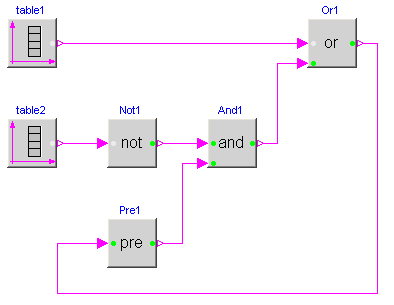
The actual value of Boolean input and/or output signals is displayed in the respective block icon as "circle", where "white" color means value false and "green" color means value true. These values are visualized in a diagram animation.
Extends from Modelica.Icons.Package (Icon for standard packages).
| Name | Description |
|---|---|
| Logical 'and': y = u1 and u2 | |
| Logical 'or': y = u1 or u2 | |
| Logical 'xor': y = u1 xor u2 | |
| Logical 'nor': y = not (u1 or u2) | |
| Logical 'nand': y = not (u1 and u2) | |
| Logical 'not': y = not u | |
| Breaks algebraic loops by an infinitesimal small time delay (y = pre(u): event iteration continues until u = pre(u)) | |
| Output y is true, if the input u has a rising edge (y = edge(u)) | |
| Output y is true, if the input u has a falling edge (y = edge(not u)) | |
| Output y is true, if the input u has a rising or falling edge (y = change(u)) | |
| Output y is true, if input u is greater than threshold | |
| Output y is true, if input u is greater or equal than threshold | |
| Output y is true, if input u is less than threshold | |
| Output y is true, if input u is less or equal than threshold | |
| Output y is true, if input u1 is greater as input u2 | |
| Output y is true, if input u1 is greater or equal as input u2 | |
| Output y is true, if input u1 is less as input u2 | |
| Output y is true, if input u1 is less or equal as input u2 | |
| Trigger zero crossing of input u | |
| Logical Switch | |
| Switch between two Real signals | |
| Transform Real to Boolean signal with Hysteresis | |
| On-off controller | |
| Triggered trapezoid generator | |
| Timer measuring the time from the time instant where the Boolean input became true | |
| Terminate simulation if condition is fullfilled |
 Modelica.Blocks.Logical.And
The output is true if all inputs are true, otherwise the output is false.
Extends from Blocks.Interfaces.partialBooleanSI2SO (Partial block with 2 input and 1 output Boolean signal).
| Type | Name | Description |
|---|---|---|
| input BooleanInput | u1 | Connector of first Boolean input signal |
| input BooleanInput | u2 | Connector of second Boolean input signal |
| output BooleanOutput | y | Connector of Boolean output signal |
model And "Logical 'and': y = u1 and u2" extends Blocks.Interfaces.partialBooleanSI2SO; equation y = u1 and u2;end And;
 Modelica.Blocks.Logical.Or
The output is true if at least one input is true, otherwise the output is false.
Extends from Blocks.Interfaces.partialBooleanSI2SO (Partial block with 2 input and 1 output Boolean signal).
| Type | Name | Description |
|---|---|---|
| input BooleanInput | u1 | Connector of first Boolean input signal |
| input BooleanInput | u2 | Connector of second Boolean input signal |
| output BooleanOutput | y | Connector of Boolean output signal |
model Or "Logical 'or': y = u1 or u2" extends Blocks.Interfaces.partialBooleanSI2SO; equation y = u1 or u2;end Or;
 Modelica.Blocks.Logical.Xor
The output is true if exactly one input is true, otherwise the output is false.
Extends from Blocks.Interfaces.partialBooleanSI2SO (Partial block with 2 input and 1 output Boolean signal).
| Type | Name | Description |
|---|---|---|
| input BooleanInput | u1 | Connector of first Boolean input signal |
| input BooleanInput | u2 | Connector of second Boolean input signal |
| output BooleanOutput | y | Connector of Boolean output signal |
model Xor "Logical 'xor': y = u1 xor u2" extends Blocks.Interfaces.partialBooleanSI2SO; equation y =not ( (u1 and u2) or (not u1 and not u2));end Xor;
 Modelica.Blocks.Logical.Nor
The output is true if none of the inputs is true, otherwise the output is false.
Extends from Blocks.Interfaces.partialBooleanSI2SO (Partial block with 2 input and 1 output Boolean signal).
| Type | Name | Description |
|---|---|---|
| input BooleanInput | u1 | Connector of first Boolean input signal |
| input BooleanInput | u2 | Connector of second Boolean input signal |
| output BooleanOutput | y | Connector of Boolean output signal |
model Nor "Logical 'nor': y = not (u1 or u2)" extends Blocks.Interfaces.partialBooleanSI2SO; equation y =not ( u1 or u2);end Nor;
 Modelica.Blocks.Logical.Nand
The output is true if at least one input is false, otherwise the output is false.
Extends from Blocks.Interfaces.partialBooleanSI2SO (Partial block with 2 input and 1 output Boolean signal).
| Type | Name | Description |
|---|---|---|
| input BooleanInput | u1 | Connector of first Boolean input signal |
| input BooleanInput | u2 | Connector of second Boolean input signal |
| output BooleanOutput | y | Connector of Boolean output signal |
model Nand "Logical 'nand': y = not (u1 and u2)" extends Blocks.Interfaces.partialBooleanSI2SO; equation y =not ( u1 and u2);end Nand;
 Modelica.Blocks.Logical.Not

The output is true if the input is false, otherwise the output is false.
Extends from Blocks.Interfaces.partialBooleanSISO (Partial block with 1 input and 1 output Boolean signal).
| Type | Name | Description |
|---|---|---|
| input BooleanInput | u | Connector of Boolean input signal |
| output BooleanOutput | y | Connector of Boolean output signal |
model Not "Logical 'not': y = not u" extends Blocks.Interfaces.partialBooleanSISO; equation y =not u;end Not;
 Modelica.Blocks.Logical.Pre
This block delays the Boolean input by an infinitesimal small time delay and therefore breaks algebraic loops. In a network of logical blocks, in every "closed connection loop" at least one logical block must have a delay, since algebraic systems of Boolean equations are not solveable.
The "Pre" block returns the value of the "input" signal from the last "event iteration". The "event iteration" stops, once both values are identical (u = pre(u)).
Extends from Blocks.Interfaces.partialBooleanSISO (Partial block with 1 input and 1 output Boolean signal).
| Type | Name | Default | Description |
|---|---|---|---|
| Boolean | pre_u_start | false | Start value of pre(u) at initial time |
| Type | Name | Description |
|---|---|---|
| input BooleanInput | u | Connector of Boolean input signal |
| output BooleanOutput | y | Connector of Boolean output signal |
model Pre "Breaks algebraic loops by an infinitesimal small time delay (y = pre(u): event iteration continues until u = pre(u))" parameter Boolean pre_u_start = false "Start value of pre(u) at initial time"; extends Blocks.Interfaces.partialBooleanSISO; initial equation pre(u) = pre_u_start; equation y = pre(u);end Pre;
 Modelica.Blocks.Logical.Edge
The output is true if the Boolean input has a rising edge from false to true, otherwise the output is false.
Extends from Blocks.Interfaces.partialBooleanSISO (Partial block with 1 input and 1 output Boolean signal).
| Type | Name | Default | Description |
|---|---|---|---|
| Boolean | pre_u_start | false | Start value of pre(u) at initial time |
| Type | Name | Description |
|---|---|---|
| input BooleanInput | u | Connector of Boolean input signal |
| output BooleanOutput | y | Connector of Boolean output signal |
model Edge "Output y is true, if the input u has a rising edge (y = edge(u))" parameter Boolean pre_u_start = false "Start value of pre(u) at initial time"; extends Blocks.Interfaces.partialBooleanSISO; initial equation pre(u) = pre_u_start; equation y = edge(u);end Edge;
 Modelica.Blocks.Logical.FallingEdge
The output is true if the Boolean input has a falling edge from true to false, otherwise the output is false.
Extends from Blocks.Interfaces.partialBooleanSISO (Partial block with 1 input and 1 output Boolean signal).
| Type | Name | Default | Description |
|---|---|---|---|
| Boolean | pre_u_start | false | Start value of pre(u) at initial time |
| Type | Name | Description |
|---|---|---|
| input BooleanInput | u | Connector of Boolean input signal |
| output BooleanOutput | y | Connector of Boolean output signal |
model FallingEdge "Output y is true, if the input u has a falling edge (y = edge(not u))" parameter Boolean pre_u_start = false "Start value of pre(u) at initial time"; extends Blocks.Interfaces.partialBooleanSISO; protected Boolean not_u=not u; initial equation pre(not_u) =not pre_u_start; equation y = edge(not_u);end FallingEdge;
 Modelica.Blocks.Logical.Change
The output is true if the Boolean input has either a rising edge from false to true or a falling edge from true to false, otherwise the output is false.
Extends from Blocks.Interfaces.partialBooleanSISO (Partial block with 1 input and 1 output Boolean signal).
| Type | Name | Default | Description |
|---|---|---|---|
| Boolean | pre_u_start | false | Start value of pre(u) at initial time |
| Type | Name | Description |
|---|---|---|
| input BooleanInput | u | Connector of Boolean input signal |
| output BooleanOutput | y | Connector of Boolean output signal |
model Change "Output y is true, if the input u has a rising or falling edge (y = change(u))" parameter Boolean pre_u_start = false "Start value of pre(u) at initial time"; extends Blocks.Interfaces.partialBooleanSISO; initial equation pre(u) = pre_u_start; equation y = change(u);end Change;
 Modelica.Blocks.Logical.GreaterThreshold

The output is true if the Real input is greater than parameter threshold, otherwise the output is false.
Extends from Blocks.Interfaces.partialBooleanThresholdComparison (Partial block to compare the Real input u with a threshold and provide the result as 1 Boolean output signal).
| Type | Name | Default | Description |
|---|---|---|---|
| Real | threshold | 0 | Comparison with respect to threshold |
| Type | Name | Description |
|---|---|---|
| input RealInput | u | Connector of Boolean input signal |
| output BooleanOutput | y | Connector of Boolean output signal |
block GreaterThreshold "Output y is true, if input u is greater than threshold" extends Blocks.Interfaces.partialBooleanThresholdComparison; equation y = u > threshold;end GreaterThreshold;
 Modelica.Blocks.Logical.GreaterEqualThreshold
The output is true if the Real input is greater than or equal to parameter threshold, otherwise the output is false.
Extends from Blocks.Interfaces.partialBooleanThresholdComparison (Partial block to compare the Real input u with a threshold and provide the result as 1 Boolean output signal).
| Type | Name | Default | Description |
|---|---|---|---|
| Real | threshold | 0 | Comparison with respect to threshold |
| Type | Name | Description |
|---|---|---|
| input RealInput | u | Connector of Boolean input signal |
| output BooleanOutput | y | Connector of Boolean output signal |
block GreaterEqualThreshold "Output y is true, if input u is greater or equal than threshold" extends Blocks.Interfaces.partialBooleanThresholdComparison; equation y = u >= threshold;end GreaterEqualThreshold;
 Modelica.Blocks.Logical.LessThreshold
The output is true if the Real input is less than parameter threshold, otherwise the output is false.
Extends from Blocks.Interfaces.partialBooleanThresholdComparison (Partial block to compare the Real input u with a threshold and provide the result as 1 Boolean output signal).
| Type | Name | Default | Description |
|---|---|---|---|
| Real | threshold | 0 | Comparison with respect to threshold |
| Type | Name | Description |
|---|---|---|
| input RealInput | u | Connector of Boolean input signal |
| output BooleanOutput | y | Connector of Boolean output signal |
block LessThreshold "Output y is true, if input u is less than threshold" extends Blocks.Interfaces.partialBooleanThresholdComparison; equation y = u < threshold;end LessThreshold;
 Modelica.Blocks.Logical.LessEqualThreshold
The output is true if the Real input is less than or equal to parameter threshold, otherwise the output is false.
Extends from Blocks.Interfaces.partialBooleanThresholdComparison (Partial block to compare the Real input u with a threshold and provide the result as 1 Boolean output signal).
| Type | Name | Default | Description |
|---|---|---|---|
| Real | threshold | 0 | Comparison with respect to threshold |
| Type | Name | Description |
|---|---|---|
| input RealInput | u | Connector of Boolean input signal |
| output BooleanOutput | y | Connector of Boolean output signal |
block LessEqualThreshold "Output y is true, if input u is less or equal than threshold" extends Blocks.Interfaces.partialBooleanThresholdComparison; equation y = u <= threshold;end LessEqualThreshold;
 Modelica.Blocks.Logical.Greater
The output is true if Real input u1 is greater than Real input u2, otherwise the output is false.
Extends from Blocks.Interfaces.partialBooleanComparison (Partial block with 2 Real input and 1 Boolean output signal (the result of a comparison of the two Real inputs).
| Type | Name | Description |
|---|---|---|
| input RealInput | u1 | Connector of first Boolean input signal |
| input RealInput | u2 | Connector of second Boolean input signal |
| output BooleanOutput | y | Connector of Boolean output signal |
block Greater "Output y is true, if input u1 is greater as input u2" extends Blocks.Interfaces.partialBooleanComparison; equation y = u1 > u2;end Greater;
 Modelica.Blocks.Logical.GreaterEqual
The output is true if Real input u1 is greater than or equal to Real input u2, otherwise the output is false.
Extends from Blocks.Interfaces.partialBooleanComparison (Partial block with 2 Real input and 1 Boolean output signal (the result of a comparison of the two Real inputs).
| Type | Name | Description |
|---|---|---|
| input RealInput | u1 | Connector of first Boolean input signal |
| input RealInput | u2 | Connector of second Boolean input signal |
| output BooleanOutput | y | Connector of Boolean output signal |
block GreaterEqual "Output y is true, if input u1 is greater or equal as input u2" extends Blocks.Interfaces.partialBooleanComparison; equation y = u1 >= u2;end GreaterEqual;
 Modelica.Blocks.Logical.Less
The output is true if Real input u1 is less than Real input u2, otherwise the output is false.
Extends from Blocks.Interfaces.partialBooleanComparison (Partial block with 2 Real input and 1 Boolean output signal (the result of a comparison of the two Real inputs).
| Type | Name | Description |
|---|---|---|
| input RealInput | u1 | Connector of first Boolean input signal |
| input RealInput | u2 | Connector of second Boolean input signal |
| output BooleanOutput | y | Connector of Boolean output signal |
block Less "Output y is true, if input u1 is less as input u2" extends Blocks.Interfaces.partialBooleanComparison; equation y = u1 < u2;end Less;
 Modelica.Blocks.Logical.LessEqual
The output is true if Real input u1 is less than or equal to Real input u2, otherwise the output is false.
Extends from Blocks.Interfaces.partialBooleanComparison (Partial block with 2 Real input and 1 Boolean output signal (the result of a comparison of the two Real inputs).
| Type | Name | Description |
|---|---|---|
| input RealInput | u1 | Connector of first Boolean input signal |
| input RealInput | u2 | Connector of second Boolean input signal |
| output BooleanOutput | y | Connector of Boolean output signal |
block LessEqual "Output y is true, if input u1 is less or equal as input u2" extends Blocks.Interfaces.partialBooleanComparison; equation y = u1 <= u2;end LessEqual;
 Modelica.Blocks.Logical.ZeroCrossing
The output "y" is true at the time instant when the input "u" becomes zero, provided the input "enable" is true. At all other time instants, the output "y" is false. If the input "u" is zero at a time instant when the "enable" input changes its value, then the output y is false.
Note, that in the plot window of a Modelica simulator, the output of this block is usually identically to false, because the output may only be true at an event instant, but not during continuous integration. In order to check that this component is actually working as expected, one should connect its output to, e.g., component ModelicaAdditions.Blocks.Discrete.TriggeredSampler.
Extends from Blocks.Interfaces.partialBooleanSO (Partial block with 1 output Boolean signal).
| Type | Name | Description |
|---|---|---|
| output BooleanOutput | y | Connector of Boolean output signal |
| input RealInput | u | |
| input BooleanInput | enable | Zero input crossing is triggered if the enable input signal is true |
block ZeroCrossing "Trigger zero crossing of input u" extends Blocks.Interfaces.partialBooleanSO;Blocks.Interfaces.RealInput u; Blocks.Interfaces.BooleanInput enable "Zero input crossing is triggered if the enable input signal is true"; protected Boolean disable=not enable; Boolean u_pos; initial equation pre(u_pos) = false; pre(enable) = false; pre(disable) =not pre(enable); equation u_pos = enable and u >= 0; y = change(u_pos) and not edge(enable) and not edge(disable);end ZeroCrossing;
 Modelica.Blocks.Logical.LogicalSwitch
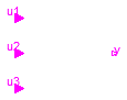
The LogicalSwitch switches, depending on the Boolean u2 connector (the middle connector), between the two possible input signals u1 (upper connector) and u3 (lower connector).
If u2 is true, connector y is set equal to u1, else it is set equal to u3.
Extends from Blocks.Interfaces.partialBooleanSI3SO (Partial block with 3 input and 1 output Boolean signal).
| Type | Name | Description |
|---|---|---|
| input BooleanInput | u1 | Connector of first Boolean input signal |
| input BooleanInput | u2 | Connector of second Boolean input signal |
| input BooleanInput | u3 | Connector of third Boolean input signal |
| output BooleanOutput | y | Connector of Boolean output signal |
block LogicalSwitch "Logical Switch" extends Blocks.Interfaces.partialBooleanSI3SO; equation y = if u2 then u1 else u3;end LogicalSwitch;
 Modelica.Blocks.Logical.Switch
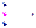
The Logical.Switch switches, depending on the logical connector u2 (the middle connector) between the two possible input signals u1 (upper connector) and u3 (lower connector).
If u2 is true, the output signal y is set equal to u1, else it is set equal to u3.
Extends from Blocks.Interfaces.partialBooleanBlockIcon (Basic graphical layout of logical block).
| Type | Name | Description |
|---|---|---|
| input RealInput | u1 | Connector of first Real input signal |
| input BooleanInput | u2 | Connector of Boolean input signal |
| input RealInput | u3 | Connector of second Real input signal |
| output RealOutput | y | Connector of Real output signal |
block Switch "Switch between two Real signals" extends Blocks.Interfaces.partialBooleanBlockIcon;Blocks.Interfaces.RealInput u1 "Connector of first Real input signal"; Blocks.Interfaces.BooleanInput u2 "Connector of Boolean input signal"; Blocks.Interfaces.RealInput u3 "Connector of second Real input signal"; Blocks.Interfaces.RealOutput y "Connector of Real output signal"; equation y = if u2 then u1 else u3;end Switch;
 Modelica.Blocks.Logical.Hysteresis
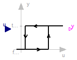
This block transforms a Real input signal into a Boolean output signal:
The start value of the output is defined via parameter pre_y_start (= value of pre(y) at initial time). The default value of this parameter is false.
Extends from Blocks.Interfaces.partialBooleanBlockIcon (Basic graphical layout of logical block).
| Type | Name | Default | Description |
|---|---|---|---|
| Real | uLow | if y=true and u<=uLow, switch to y=false | |
| Real | uHigh | if y=false and u>=uHigh, switch to y=true | |
| Boolean | pre_y_start | false | Value of pre(y) at initial time |
| Type | Name | Description |
|---|---|---|
| input RealInput | u | |
| output BooleanOutput | y |
block Hysteresis "Transform Real to Boolean signal with Hysteresis" extends Blocks.Interfaces.partialBooleanBlockIcon; parameter Real uLow(start=0) "if y=true and u<=uLow, switch to y=false"; parameter Real uHigh(start=1) "if y=false and u>=uHigh, switch to y=true"; parameter Boolean pre_y_start = false "Value of pre(y) at initial time";Blocks.Interfaces.RealInput u; Blocks.Interfaces.BooleanOutput y; initial equation pre(y) = pre_y_start; equation y = u > uHigh or pre(y) and u >= uLow;end Hysteresis;
 Modelica.Blocks.Logical.OnOffController
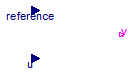
The block OnOffController sets the output signal y to true when the input signal u falls below the reference signal minus half of the bandwidth and sets the output signal y to false when the input signal u exceeds the reference signal plus half of the bandwidth.
Extends from Interfaces.partialBooleanBlockIcon (Basic graphical layout of logical block).
| Type | Name | Default | Description |
|---|---|---|---|
| Real | bandwidth | Bandwidth around reference signal | |
| Boolean | pre_y_start | false | Value of pre(y) at initial time |
| Type | Name | Description |
|---|---|---|
| input RealInput | reference | Connector of Real input signal used as reference signal |
| input RealInput | u | Connector of Real input signal used as measurement signal |
| output BooleanOutput | y | Connector of Real output signal used as actuator signal |
block OnOffController "On-off controller" extends Interfaces.partialBooleanBlockIcon;Blocks.Interfaces.RealInput reference "Connector of Real input signal used as reference signal"; Blocks.Interfaces.RealInput u "Connector of Real input signal used as measurement signal"; Blocks.Interfaces.BooleanOutput y "Connector of Real output signal used as actuator signal"; parameter Real bandwidth(start=0.1) "Bandwidth around reference signal"; parameter Boolean pre_y_start = false "Value of pre(y) at initial time"; initial equation pre(y) = pre_y_start; equation y = pre(y) and (u < reference + bandwidth/2) or (u < reference - bandwidth/2);end OnOffController;
 Modelica.Blocks.Logical.TriggeredTrapezoid
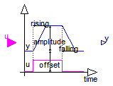
The block TriggeredTrapezoid has a boolean input and a real output signal and requires the parameters amplitude, rising, falling and offset. The output signal y represents a trapezoidal signal dependent on the input signal u.
The behaviour is as follows: Assume the initial input to be false. In this case, the output will be offset. After a rising edge (i.e., the input changes from false to true), the output is rising during rising to the sum of offset and amplitude. In contrast, after a falling edge (i.e., the input changes from true to false), the output is falling during falling to a value of offset.
Note, that the case of edges before expiration of rising or falling is handled properly.
Extends from Interfaces.partialBooleanBlockIcon (Basic graphical layout of logical block).
| Type | Name | Default | Description |
|---|---|---|---|
| Real | amplitude | 1 | Amplitude of trapezoid |
| Time | rising | 0 | Rising duration of trapezoid [s] |
| Time | falling | rising | Falling duration of trapezoid [s] |
| Real | offset | 0 | Offset of output signal |
| Type | Name | Description |
|---|---|---|
| input BooleanInput | u | Connector of Boolean input signal |
| output RealOutput | y | Connector of Real output signal |
block TriggeredTrapezoid "Triggered trapezoid generator"
  extends Interfaces.partialBooleanBlockIcon;

  parameter Real amplitude=1 "Amplitude of trapezoid";
  parameter Modelica.SIunits.Time rising(final min=0)=0
    "Rising duration of trapezoid";
  parameter Modelica.SIunits.Time falling(final min=0)=rising
    "Falling duration of trapezoid";
  parameter Real offset=0 "Offset of output signal";

  Blocks.Interfaces.BooleanInput u "Connector of Boolean input signal";
  Blocks.Interfaces.RealOutput y "Connector of Real output signal";

protected
  discrete Real endValue "Value of y at time of recent edge";
  discrete Real rate "Current rising/falling rate";
  discrete Modelica.SIunits.Time T "Predicted time of output reaching endValue";
initial equation
  /* A start value of y is set, because pre(y) is present
     to avoid a warning message from the compiler. However,
     this setting does not have an effect, because y is initialized
     correctly, before pre(y) is used
  */
  pre(y) = 0;
equation
    y = if time < T then endValue - (T - time)*rate else  endValue;

    when {initial(),u,not u} then
      endValue = if u then offset + amplitude else offset;
      rate = if u and (rising > 0) then amplitude/rising else
        if not u and (falling > 0) then -amplitude/falling else 0;
      T = if u and not (rising > 0) or not u and not (falling
         > 0) or not abs(amplitude) > 0 or initial() then time else time
         + (endValue - pre(y))/rate;
    end when;
end TriggeredTrapezoid;
 Modelica.Blocks.Logical.Timer
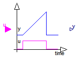
When the Boolean input "u" becomes true, the timer is started and the output "y" is the time from the time instant where u became true. The timer is stopped and the output is reset to zero, once the input becomes false.
Extends from Interfaces.partialBooleanBlockIcon (Basic graphical layout of logical block).
| Type | Name | Description |
|---|---|---|
| input BooleanInput | u | Connector of Boolean input signal |
| output RealOutput | y | Connector of Real output signal |
block Timer "Timer measuring the time from the time instant where the Boolean input became true" extends Interfaces.partialBooleanBlockIcon;Blocks.Interfaces.BooleanInput u "Connector of Boolean input signal"; Blocks.Interfaces.RealOutput y "Connector of Real output signal"; protected discrete Modelica.SIunits.Time entryTime "Time instant when u became true"; initial equation pre(entryTime) = 0; equation when u then entryTime = time; end when; y = if u then time - entryTime else 0.0;end Timer;
 Modelica.Blocks.Logical.TerminateSimulation

In the parameter menu, a time varying expression can be defined via variable condition, for example "condition = x < 0", where "x" is a variable that is declared in the model in which the "TerminateSimulation" block is present. If this expression becomes true, the simulation is (successfully) terminated. A termination message explaining the reason for the termination can be given via parameter "terminationText".
| Type | Name | Default | Description |
|---|---|---|---|
| BooleanOutput | condition | false | Terminate simulation when condition becomes true |
| String | terminationText | "... End condition reached" | Text that will be displayed when simulation is terminated |
| Type | Name | Description |
|---|---|---|
| output BooleanOutput | condition | Terminate simulation when condition becomes true |
block TerminateSimulation "Terminate simulation if condition is fullfilled"Modelica.Blocks.Interfaces.BooleanOutput condition=false "Terminate simulation when condition becomes true"; parameter String terminationText = "... End condition reached" "Text that will be displayed when simulation is terminated"; equation when condition then terminate(terminationText); end when;end TerminateSimulation;