| Name | Description |
|---|---|
| Package with borehole heat exchangers | |
| Package with cooling tower models | |
| DX(Direct Expansion) cooling coil models | |
| Package with radiators models for hydronic space heating systems | |
| Package with radiant slab models | |
| Heat exchanger with constant effectiveness | |
| Heat exchanger with effectiveness - NTU relation and no moisture condensation | |
| Counterflow coil with discretization along the flow paths and without humidity condensation | |
| Counterflow coil with discretization along the flow paths and humidity condensation | |
| Coil with discretization along the flow paths and no humidity condensation | |
| Coil with discretization along the flow paths and humidity condensation | |
| Heater or cooler with prescribed heat flow rate | |
| Collection of models that illustrate model use and test models | |
| Package with base classes for Buildings.Fluid.HeatExchangers |
 Buildings.Fluid.HeatExchangers.ConstantEffectiveness
Model for a heat exchanger with constant effectiveness.
This model transfers heat in the amount of
Q = Qmax ε,
where ε is a constant effectiveness and Qmax is the maximum heat that can be transferred.
For a heat and moisture exchanger, use Buildings.Fluid.MassExchangers.ConstantEffectiveness instead of this model.
Extends from Buildings.Fluid.HeatExchangers.BaseClasses.PartialEffectiveness (Partial model to implement heat exchangers based on effectiveness model).
| Type | Name | Default | Description |
|---|---|---|---|
| replaceable package Medium1 | PartialMedium | Medium 1 in the component | |
| replaceable package Medium2 | PartialMedium | Medium 2 in the component | |
| HeatFlowRate | Q1_flow | eps*QMax_flow | Heat transfered into the medium 1 [W] |
| MassFlowRate | mWat1_flow | 0 | Moisture mass flow rate added to the medium 1 [kg/s] |
| HeatFlowRate | Q2_flow | -Q1_flow | Heat transfered into the medium 2 [W] |
| MassFlowRate | mWat2_flow | 0 | Moisture mass flow rate added to the medium 2 [kg/s] |
| Boolean | sensibleOnly1 | true | Set to true if sensible exchange only for medium 1 |
| Boolean | sensibleOnly2 | true | Set to true if sensible exchange only for medium 2 |
| Real | eps | 0.8 | Heat exchanger effectiveness [1] |
| Nominal condition | |||
| MassFlowRate | m1_flow_nominal | Nominal mass flow rate [kg/s] | |
| MassFlowRate | m2_flow_nominal | Nominal mass flow rate [kg/s] | |
| Pressure | dp1_nominal | Pressure [Pa] | |
| Pressure | dp2_nominal | Pressure [Pa] | |
| Initialization | |||
| MassFlowRate | m1_flow.start | 0 | Mass flow rate from port_a1 to port_b1 (m1_flow > 0 is design flow direction) [kg/s] |
| Pressure | dp1.start | 0 | Pressure difference between port_a1 and port_b1 [Pa] |
| MassFlowRate | m2_flow.start | 0 | Mass flow rate from port_a2 to port_b2 (m2_flow > 0 is design flow direction) [kg/s] |
| Pressure | dp2.start | 0 | Pressure difference between port_a2 and port_b2 [Pa] |
| Assumptions | |||
| Boolean | allowFlowReversal1 | system.allowFlowReversal | = true to allow flow reversal in medium 1, false restricts to design direction (port_a -> port_b) |
| Boolean | allowFlowReversal2 | system.allowFlowReversal | = true to allow flow reversal in medium 2, false restricts to design direction (port_a -> port_b) |
| Advanced | |||
| Initialization | |||
| SpecificEnthalpy | h_outflow_a1_start | Medium1.h_default | Start value for enthalpy flowing out of port a1 [J/kg] |
| SpecificEnthalpy | h_outflow_b1_start | Medium1.h_default | Start value for enthalpy flowing out of port b1 [J/kg] |
| SpecificEnthalpy | h_outflow_a2_start | Medium2.h_default | Start value for enthalpy flowing out of port a2 [J/kg] |
| SpecificEnthalpy | h_outflow_b2_start | Medium2.h_default | Start value for enthalpy flowing out of port b2 [J/kg] |
| MassFlowRate | m1_flow_small | 1E-4*abs(m1_flow_nominal) | Small mass flow rate for regularization of zero flow [kg/s] |
| MassFlowRate | m2_flow_small | 1E-4*abs(m2_flow_nominal) | Small mass flow rate for regularization of zero flow [kg/s] |
| Boolean | homotopyInitialization | true | = true, use homotopy method |
| Diagnostics | |||
| Boolean | show_T | false | = true, if actual temperature at port is computed |
| Flow resistance | |||
| Medium 1 | |||
| Boolean | from_dp1 | false | = true, use m_flow = f(dp) else dp = f(m_flow) |
| Boolean | linearizeFlowResistance1 | false | = true, use linear relation between m_flow and dp for any flow rate |
| Real | deltaM1 | 0.1 | Fraction of nominal flow rate where flow transitions to laminar |
| Medium 2 | |||
| Boolean | from_dp2 | false | = true, use m_flow = f(dp) else dp = f(m_flow) |
| Boolean | linearizeFlowResistance2 | false | = true, use linear relation between m_flow and dp for any flow rate |
| Real | deltaM2 | 0.1 | Fraction of nominal flow rate where flow transitions to laminar |
| Type | Name | Description |
|---|---|---|
| FluidPort_a | port_a1 | Fluid connector a1 (positive design flow direction is from port_a1 to port_b1) |
| FluidPort_b | port_b1 | Fluid connector b1 (positive design flow direction is from port_a1 to port_b1) |
| FluidPort_a | port_a2 | Fluid connector a2 (positive design flow direction is from port_a2 to port_b2) |
| FluidPort_b | port_b2 | Fluid connector b2 (positive design flow direction is from port_a2 to port_b2) |
model ConstantEffectiveness
  "Heat exchanger with constant effectiveness"
  extends Buildings.Fluid.HeatExchangers.BaseClasses.PartialEffectiveness(
    sensibleOnly1 = true,
    sensibleOnly2 = true,
    Q1_flow = eps * QMax_flow,
    Q2_flow = -Q1_flow,
    mWat1_flow = 0,
    mWat2_flow = 0);

  parameter Real eps(min=0, max=1, unit="1") = 0.8
    "Heat exchanger effectiveness";
equation

end ConstantEffectiveness;
Buildings.Fluid.HeatExchangers.DryEffectivenessNTU
Model of a heat exchanger without humidity condensation. This model transfers heat in the amount of
Q = Qmax ε
ε = f(NTU, Z, flowRegime),
where Qmax is the maximum heat that can be transferred, ε is the heat transfer effectiveness, NTU is the Number of Transfer Units, Z is the ratio of minimum to maximum capacity flow rate and flowRegime is the heat exchanger flow regime. such as parallel flow, cross flow or counter flow.
The flow regimes depend on the heat exchanger configuration. All configurations defined in Buildings.Fluid.Types.HeatExchangerConfiguration are supported.
For a heat and moisture exchanger, use Buildings.Fluid.MassExchangers.ConstantEffectiveness instead of this model.
Extends from Buildings.Fluid.HeatExchangers.BaseClasses.PartialEffectiveness (Partial model to implement heat exchangers based on effectiveness model).
| Type | Name | Default | Description |
|---|---|---|---|
| replaceable package Medium1 | PartialMedium | Medium 1 in the component | |
| replaceable package Medium2 | PartialMedium | Medium 2 in the component | |
| HeatFlowRate | Q1_flow | eps*QMax_flow | Heat transfered into the medium 1 [W] |
| MassFlowRate | mWat1_flow | 0 | Moisture mass flow rate added to the medium 1 [kg/s] |
| HeatFlowRate | Q2_flow | -Q1_flow | Heat transfered into the medium 2 [W] |
| MassFlowRate | mWat2_flow | 0 | Moisture mass flow rate added to the medium 2 [kg/s] |
| Boolean | sensibleOnly1 | true | Set to true if sensible exchange only for medium 1 |
| Boolean | sensibleOnly2 | true | Set to true if sensible exchange only for medium 2 |
| HeatExchangerConfiguration | configuration | Heat exchanger configuration | |
| Real | r_nominal | 2/3 | Ratio between air-side and water-side convective heat transfer (hA-value) at nominal condition |
| Nominal condition | |||
| MassFlowRate | m1_flow_nominal | Nominal mass flow rate [kg/s] | |
| MassFlowRate | m2_flow_nominal | Nominal mass flow rate [kg/s] | |
| Pressure | dp1_nominal | Pressure [Pa] | |
| Pressure | dp2_nominal | Pressure [Pa] | |
| HeatFlowRate | Q_flow_nominal | Nominal heat transfer [W] | |
| Temperature | T_a1_nominal | Nominal temperature at port a1 [K] | |
| Temperature | T_a2_nominal | Nominal temperature at port a2 [K] | |
| Initialization | |||
| MassFlowRate | m1_flow.start | 0 | Mass flow rate from port_a1 to port_b1 (m1_flow > 0 is design flow direction) [kg/s] |
| Pressure | dp1.start | 0 | Pressure difference between port_a1 and port_b1 [Pa] |
| MassFlowRate | m2_flow.start | 0 | Mass flow rate from port_a2 to port_b2 (m2_flow > 0 is design flow direction) [kg/s] |
| Pressure | dp2.start | 0 | Pressure difference between port_a2 and port_b2 [Pa] |
| Assumptions | |||
| Boolean | allowFlowReversal1 | system.allowFlowReversal | = true to allow flow reversal in medium 1, false restricts to design direction (port_a -> port_b) |
| Boolean | allowFlowReversal2 | system.allowFlowReversal | = true to allow flow reversal in medium 2, false restricts to design direction (port_a -> port_b) |
| Advanced | |||
| Initialization | |||
| SpecificEnthalpy | h_outflow_a1_start | Medium1.h_default | Start value for enthalpy flowing out of port a1 [J/kg] |
| SpecificEnthalpy | h_outflow_b1_start | Medium1.h_default | Start value for enthalpy flowing out of port b1 [J/kg] |
| SpecificEnthalpy | h_outflow_a2_start | Medium2.h_default | Start value for enthalpy flowing out of port a2 [J/kg] |
| SpecificEnthalpy | h_outflow_b2_start | Medium2.h_default | Start value for enthalpy flowing out of port b2 [J/kg] |
| MassFlowRate | m1_flow_small | 1E-4*abs(m1_flow_nominal) | Small mass flow rate for regularization of zero flow [kg/s] |
| MassFlowRate | m2_flow_small | 1E-4*abs(m2_flow_nominal) | Small mass flow rate for regularization of zero flow [kg/s] |
| Boolean | homotopyInitialization | true | = true, use homotopy method |
| Diagnostics | |||
| Boolean | show_T | false | = true, if actual temperature at port is computed |
| Flow resistance | |||
| Medium 1 | |||
| Boolean | from_dp1 | false | = true, use m_flow = f(dp) else dp = f(m_flow) |
| Boolean | linearizeFlowResistance1 | false | = true, use linear relation between m_flow and dp for any flow rate |
| Real | deltaM1 | 0.1 | Fraction of nominal flow rate where flow transitions to laminar |
| Medium 2 | |||
| Boolean | from_dp2 | false | = true, use m_flow = f(dp) else dp = f(m_flow) |
| Boolean | linearizeFlowResistance2 | false | = true, use linear relation between m_flow and dp for any flow rate |
| Real | deltaM2 | 0.1 | Fraction of nominal flow rate where flow transitions to laminar |
| Type | Name | Description |
|---|---|---|
| FluidPort_a | port_a1 | Fluid connector a1 (positive design flow direction is from port_a1 to port_b1) |
| FluidPort_b | port_b1 | Fluid connector b1 (positive design flow direction is from port_a1 to port_b1) |
| FluidPort_a | port_a2 | Fluid connector a2 (positive design flow direction is from port_a2 to port_b2) |
| FluidPort_b | port_b2 | Fluid connector b2 (positive design flow direction is from port_a2 to port_b2) |
model DryEffectivenessNTU
  "Heat exchanger with effectiveness - NTU relation and no moisture condensation"
  extends Buildings.Fluid.HeatExchangers.BaseClasses.PartialEffectiveness(
      sensibleOnly1=true, sensibleOnly2=true,
      Q1_flow = eps*QMax_flow,
      Q2_flow = -Q1_flow,
      mWat1_flow = 0,
      mWat2_flow = 0);
  import con = Buildings.Fluid.Types.HeatExchangerConfiguration;
  import flo = Buildings.Fluid.Types.HeatExchangerFlowRegime;
  parameter Modelica.SIunits.HeatFlowRate Q_flow_nominal
    "Nominal heat transfer";
  parameter Modelica.SIunits.Temperature T_a1_nominal
    "Nominal temperature at port a1";
  parameter Modelica.SIunits.Temperature T_a2_nominal
    "Nominal temperature at port a2";
  parameter con configuration "Heat exchanger configuration";
  parameter Real r_nominal(
    min=0,
    max=1) = 2/3
    "Ratio between air-side and water-side convective heat transfer (hA-value) at nominal condition";
  Buildings.Fluid.HeatExchangers.BaseClasses.HADryCoil hA(
    final r_nominal=r_nominal,
    final UA_nominal=UA_nominal,
    final m_flow_nominal_w=m1_flow_nominal,
    final m_flow_nominal_a=m2_flow_nominal,
    waterSideTemperatureDependent=false,
    airSideTemperatureDependent=false)
    "Model for convective heat transfer coefficient";
  Modelica.SIunits.ThermalConductance UA "UA value";
  Real eps(min=0, max=1) "Heat exchanger effectiveness";
  Real Z(min=0, max=1) "Ratio of capacity flow rate (CMin/CMax)";
  // NTU has been removed as NTU goes to infinity as CMin goes to zero.
  // This quantity is not good for modeling.
  //  Real NTU(min=0) "Number of transfer units";
  final parameter Modelica.SIunits.ThermalConductance UA_nominal(fixed=false)
    "Nominal UA value";
  final parameter Real NTU_nominal(min=0, fixed=false)
    "Nominal number of transfer units";
  final parameter Real eps_nominal(fixed=false)
    "Nominal heat transfer effectiveness";
protected
  parameter Modelica.SIunits.SpecificHeatCapacity cp1_nominal(fixed=false)
    "Specific heat capacity of medium 1 at nominal condition";
  parameter Modelica.SIunits.SpecificHeatCapacity cp2_nominal(fixed=false)
    "Specific heat capacity of medium 2 at nominal condition";
  parameter Modelica.SIunits.ThermalConductance C1_flow_nominal(fixed=false)
    "Nominal capacity flow rate of Medium 1";
  parameter Modelica.SIunits.ThermalConductance C2_flow_nominal(fixed=false)
    "Nominal capacity flow rate of Medium 2";
  parameter Modelica.SIunits.ThermalConductance CMin_flow_nominal(fixed=false)
    "Minimal capacity flow rate at nominal condition";
  parameter Modelica.SIunits.ThermalConductance CMax_flow_nominal(fixed=false)
    "Maximum capacity flow rate at nominal condition";
  parameter Real Z_nominal(
    min=0,
    max=1,
    fixed=false) "Ratio of capacity flow rate at nominal condition";
  parameter Modelica.SIunits.Temperature T_b1_nominal(fixed=false)
    "Nominal temperature at port b1";
  parameter Modelica.SIunits.Temperature T_b2_nominal(fixed=false)
    "Nominal temperature at port b2";
  parameter flo flowRegime_nominal(fixed=false)
    "Heat exchanger flow regime at nominal flow rates";
  flo flowRegime(fixed=false, start=flowRegime_nominal)
    "Heat exchanger flow regime";
initial equation
  assert(m1_flow_nominal > 0,
    "m1_flow_nominal must be positive, m1_flow_nominal = " + String(
    m1_flow_nominal));
  assert(m2_flow_nominal > 0,
    "m2_flow_nominal must be positive, m2_flow_nominal = " + String(
    m2_flow_nominal));
  cp1_nominal = Medium1.specificHeatCapacityCp(Medium1.setState_pTX(
    Medium1.p_default,
    T_a1_nominal,
    Medium1.X_default));
  cp2_nominal = Medium2.specificHeatCapacityCp(Medium2.setState_pTX(
    Medium2.p_default,
    T_a2_nominal,
    Medium2.X_default));
  // heat transfered from fluid 1 to 2 at nominal condition
  Q_flow_nominal = m1_flow_nominal*cp1_nominal*(T_a1_nominal - T_b1_nominal);
  Q_flow_nominal = -m2_flow_nominal*cp2_nominal*(T_a2_nominal - T_b2_nominal);
  C1_flow_nominal = m1_flow_nominal*cp1_nominal;
  C2_flow_nominal = m2_flow_nominal*cp2_nominal;
  CMin_flow_nominal = min(C1_flow_nominal, C2_flow_nominal);
  CMax_flow_nominal = max(C1_flow_nominal, C2_flow_nominal);
  Z_nominal = CMin_flow_nominal/CMax_flow_nominal;
  eps_nominal = abs(Q_flow_nominal/((T_a1_nominal - T_a2_nominal)*
    CMin_flow_nominal));
  assert(eps_nominal > 0 and eps_nominal < 1,
    "eps_nominal out of bounds, eps_nominal = " + String(eps_nominal) +
    "\n  To achieve the required heat transfer rate at epsilon=0.8, set |T_a1_nominal-T_a2_nominal| = "
     + String(abs(Q_flow_nominal/0.8*CMin_flow_nominal)) +
    "\n  or increase flow rates. The current parameters result in " +
    "\n  CMin_flow_nominal = " + String(CMin_flow_nominal) +
    "\n  CMax_flow_nominal = " + String(CMax_flow_nominal));
  // Assign the flow regime for the given heat exchanger configuration and capacity flow rates
  if (configuration == con.CrossFlowStream1MixedStream2Unmixed) then
    flowRegime_nominal = if (C1_flow_nominal < C2_flow_nominal) then flo.CrossFlowCMinMixedCMaxUnmixed
       else flo.CrossFlowCMinUnmixedCMaxMixed;
  elseif (configuration == con.CrossFlowStream1UnmixedStream2Mixed) then
    flowRegime_nominal = if (C1_flow_nominal < C2_flow_nominal) then flo.CrossFlowCMinUnmixedCMaxMixed
       else flo.CrossFlowCMinMixedCMaxUnmixed;
  elseif (configuration == con.ParallelFlow) then
    flowRegime_nominal = flo.ParallelFlow;
  elseif (configuration == con.CounterFlow) then
    flowRegime_nominal = flo.CounterFlow;
  elseif (configuration == con.CrossFlowUnmixed) then
    flowRegime_nominal = flo.CrossFlowUnmixed;
  else
    flowRegime_nominal = 0;
    assert(configuration > 0 and configuration < 6,
      "Invalid heat exchanger configuration.");
  end if;
  // The equation sorter of Dymola 7.3 does not guarantee that the above assert is tested prior to the
  // function call on the next line. Thus, we add the test on eps_nominal to avoid an error in ntu_epsilonZ
  // for invalid input arguments
  NTU_nominal = if (eps_nominal > 0 and eps_nominal < 1) then
    Buildings.Fluid.HeatExchangers.BaseClasses.ntu_epsilonZ(
    eps=eps_nominal,
    Z=Z_nominal,
    flowRegime=flowRegime_nominal) else 0;
  UA_nominal = NTU_nominal*CMin_flow_nominal;
equation
  // Assign the flow regime for the given heat exchanger configuration and capacity flow rates
  if (configuration == con.ParallelFlow) then
    flowRegime = if (C1_flow*C2_flow >= 0) then flo.ParallelFlow else flo.CounterFlow;
  elseif (configuration == con.CounterFlow) then
    flowRegime = if (C1_flow*C2_flow >= 0) then flo.CounterFlow else flo.ParallelFlow;
  elseif (configuration == con.CrossFlowUnmixed) then
    flowRegime = flo.CrossFlowUnmixed;
  elseif (configuration == con.CrossFlowStream1MixedStream2Unmixed) then
    flowRegime = if (C1_flow < C2_flow) then flo.CrossFlowCMinMixedCMaxUnmixed
       else flo.CrossFlowCMinUnmixedCMaxMixed;
  else
    // have ( configuration == con.CrossFlowStream1UnmixedStream2Mixed)
    flowRegime = if (C1_flow < C2_flow) then flo.CrossFlowCMinUnmixedCMaxMixed
       else flo.CrossFlowCMinMixedCMaxUnmixed;
  end if;
  // Convective heat transfer coefficient
  hA.m1_flow = m1_flow;
  hA.m2_flow = m2_flow;
  hA.T_1 = T_in1;
  hA.T_2 = T_in2;
  UA = 1/(1/hA.hA_1 + 1/hA.hA_2);
  // effectiveness
  (eps,Z) = Buildings.Fluid.HeatExchangers.BaseClasses.epsilon_C(
    UA=UA,
    C1_flow=C1_flow,
    C2_flow=C2_flow,
    flowRegime=flowRegime,
    CMin_flow_nominal=CMin_flow_nominal,
    CMax_flow_nominal=CMax_flow_nominal,
    delta=delta);
end DryEffectivenessNTU;
 Buildings.Fluid.HeatExchangers.DryCoilCounterFlow
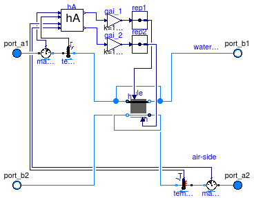
Model of a discretized coil without water vapor condensation.
The coil consists of two flow paths which are, at the design flow direction,
in opposite direction to model a counterflow heat exchanger.
The flow paths are discretized into nEle elements.
Each element is modeled by an instance of
Buildings.Fluid.HeatExchangers.BaseClasses.HexElement.
Each element has a state variable for the metal. Depending
on the value of the boolean parameters steadyState_1 and
steadyState_2, the fluid states are modeled dynamically or in steady
state.
The convective heat transfer coefficients can, for each fluid individually, be computed as a function of the flow rate and/or the temperature, or assigned to a constant. This computation is done using an instance of Buildings.Fluid.HeatExchangers.BaseClasses.HADryCoil.
To model humidity condensation, use the model Buildings.Fluid.HeatExchangers.WetCoilCounterFlow instead of this model, as this model computes only sensible heat transfer.
Extends from Fluid.Interfaces.PartialFourPortInterface (Partial model transporting fluid between two ports without storing mass or energy), Buildings.Fluid.Interfaces.FourPortFlowResistanceParameters (Parameters for flow resistance for models with four ports).
| Type | Name | Default | Description |
|---|---|---|---|
| replaceable package Medium1 | PartialMedium | Medium 1 in the component | |
| replaceable package Medium2 | PartialMedium | Medium 2 in the component | |
| Nominal condition | |||
| MassFlowRate | m1_flow_nominal | Nominal mass flow rate [kg/s] | |
| MassFlowRate | m2_flow_nominal | Nominal mass flow rate [kg/s] | |
| Pressure | dp1_nominal | Pressure [Pa] | |
| Pressure | dp2_nominal | Pressure [Pa] | |
| ThermalConductance | UA_nominal | Thermal conductance at nominal flow, used to compute heat capacity [W/K] | |
| Real | r_nominal | 2/3 | Ratio between air-side and water-side convective heat transfer coefficient |
| Time | tau1 | 20 | Time constant at nominal flow for medium 1 [s] |
| Time | tau2 | 1 | Time constant at nominal flow for medium 2 [s] |
| Time | tau_m | 20 | Time constant of metal at nominal UA value [s] |
| Initialization | |||
| MassFlowRate | m1_flow.start | 0 | Mass flow rate from port_a1 to port_b1 (m1_flow > 0 is design flow direction) [kg/s] |
| Pressure | dp1.start | 0 | Pressure difference between port_a1 and port_b1 [Pa] |
| MassFlowRate | m2_flow.start | 0 | Mass flow rate from port_a2 to port_b2 (m2_flow > 0 is design flow direction) [kg/s] |
| Pressure | dp2.start | 0 | Pressure difference between port_a2 and port_b2 [Pa] |
| Geometry | |||
| Integer | nEle | 4 | Number of pipe segments used for discretization |
| Assumptions | |||
| Boolean | allowFlowReversal1 | system.allowFlowReversal | = true to allow flow reversal in medium 1, false restricts to design direction (port_a -> port_b) |
| Boolean | allowFlowReversal2 | system.allowFlowReversal | = true to allow flow reversal in medium 2, false restricts to design direction (port_a -> port_b) |
| Advanced | |||
| Initialization | |||
| SpecificEnthalpy | h_outflow_a1_start | Medium1.h_default | Start value for enthalpy flowing out of port a1 [J/kg] |
| SpecificEnthalpy | h_outflow_b1_start | Medium1.h_default | Start value for enthalpy flowing out of port b1 [J/kg] |
| SpecificEnthalpy | h_outflow_a2_start | Medium2.h_default | Start value for enthalpy flowing out of port a2 [J/kg] |
| SpecificEnthalpy | h_outflow_b2_start | Medium2.h_default | Start value for enthalpy flowing out of port b2 [J/kg] |
| MassFlowRate | m1_flow_small | 1E-4*abs(m1_flow_nominal) | Small mass flow rate for regularization of zero flow [kg/s] |
| MassFlowRate | m2_flow_small | 1E-4*abs(m2_flow_nominal) | Small mass flow rate for regularization of zero flow [kg/s] |
| Boolean | homotopyInitialization | true | = true, use homotopy method |
| Diagnostics | |||
| Boolean | show_T | false | = true, if actual temperature at port is computed |
| Flow resistance | |||
| Medium 1 | |||
| Boolean | computeFlowResistance1 | false | =true, compute flow resistance. Set to false to assume no friction |
| Boolean | from_dp1 | false | = true, use m_flow = f(dp) else dp = f(m_flow) |
| Boolean | linearizeFlowResistance1 | false | = true, use linear relation between m_flow and dp for any flow rate |
| Real | deltaM1 | 0.1 | Fraction of nominal flow rate where flow transitions to laminar |
| Medium 2 | |||
| Boolean | computeFlowResistance2 | false | =true, compute flow resistance. Set to false to assume no friction |
| Boolean | from_dp2 | false | = true, use m_flow = f(dp) else dp = f(m_flow) |
| Boolean | linearizeFlowResistance2 | false | = true, use linear relation between m_flow and dp for any flow rate |
| Real | deltaM2 | 0.1 | Fraction of nominal flow rate where flow transitions to laminar |
| Dynamics | |||
| Equations | |||
| Dynamics | energyDynamics1 | Modelica.Fluid.Types.Dynamic... | Default formulation of energy balances for volume 1 |
| Dynamics | energyDynamics2 | Modelica.Fluid.Types.Dynamic... | Default formulation of energy balances for volume 2 |
| Heat transfer | |||
| Boolean | waterSideFlowDependent | true | Set to false to make water-side hA independent of mass flow rate |
| Boolean | airSideFlowDependent | true | Set to false to make air-side hA independent of mass flow rate |
| Boolean | waterSideTemperatureDependent | false | Set to false to make water-side hA independent of temperature |
| Boolean | airSideTemperatureDependent | false | Set to false to make air-side hA independent of temperature |
| Type | Name | Description |
|---|---|---|
| FluidPort_a | port_a1 | Fluid connector a1 (positive design flow direction is from port_a1 to port_b1) |
| FluidPort_b | port_b1 | Fluid connector b1 (positive design flow direction is from port_a1 to port_b1) |
| FluidPort_a | port_a2 | Fluid connector a2 (positive design flow direction is from port_a2 to port_b2) |
| FluidPort_b | port_b2 | Fluid connector b2 (positive design flow direction is from port_a2 to port_b2) |
model DryCoilCounterFlow
  "Counterflow coil with discretization along the flow paths and without humidity condensation"
  extends Fluid.Interfaces.PartialFourPortInterface(show_T=false);
  extends Buildings.Fluid.Interfaces.FourPortFlowResistanceParameters(
    final computeFlowResistance1=false,
    final computeFlowResistance2=false,
    from_dp1=false,
    from_dp2=false);

  parameter Modelica.SIunits.ThermalConductance UA_nominal(min=0)
    "Thermal conductance at nominal flow, used to compute heat capacity";
  parameter Real r_nominal=2/3
    "Ratio between air-side and water-side convective heat transfer coefficient";
  parameter Integer nEle(min=1) = 4
    "Number of pipe segments used for discretization";

  parameter Modelica.Fluid.Types.Dynamics energyDynamics1=Modelica.Fluid.Types.Dynamics.DynamicFreeInitial
    "Default formulation of energy balances for volume 1";
  parameter Modelica.Fluid.Types.Dynamics energyDynamics2=Modelica.Fluid.Types.Dynamics.DynamicFreeInitial
    "Default formulation of energy balances for volume 2";

  parameter Modelica.SIunits.Time tau1=20
    "Time constant at nominal flow for medium 1";
  parameter Modelica.SIunits.Time tau2=1
    "Time constant at nominal flow for medium 2";
  parameter Modelica.SIunits.Time tau_m=20
    "Time constant of metal at nominal UA value";

  parameter Boolean waterSideFlowDependent=true
    "Set to false to make water-side hA independent of mass flow rate";
  parameter Boolean airSideFlowDependent=true
    "Set to false to make air-side hA independent of mass flow rate";
  parameter Boolean waterSideTemperatureDependent=false
    "Set to false to make water-side hA independent of temperature";
  parameter Boolean airSideTemperatureDependent=false
    "Set to false to make air-side hA independent of temperature";

  Modelica.SIunits.HeatFlowRate Q1_flow
    "Heat transfered from solid into medium 1";
  Modelica.SIunits.HeatFlowRate Q2_flow
    "Heat transfered from solid into medium 2";

  Modelica.SIunits.Temperature T1[nEle] "Water temperature";
  Modelica.SIunits.Temperature T2[nEle] "Air temperature";
  Modelica.SIunits.Temperature T_m[nEle] "Metal temperature";

  BaseClasses.HADryCoil hA(
    final UA_nominal=UA_nominal,
    final m_flow_nominal_a=m2_flow_nominal,
    final m_flow_nominal_w=m1_flow_nominal,
    final waterSideTemperatureDependent=waterSideTemperatureDependent,
    final waterSideFlowDependent=waterSideFlowDependent,
    final airSideTemperatureDependent=airSideTemperatureDependent,
    final airSideFlowDependent=airSideFlowDependent,
    r_nominal=r_nominal) "Model for convective heat transfer coefficient";
protected
  Buildings.Fluid.Sensors.TemperatureTwoPort temSen_1(redeclare package Medium
      = Medium1,
    allowFlowReversal=allowFlowReversal1,
    m_flow_nominal=m1_flow_nominal) "Temperature sensor";
  Buildings.Fluid.Sensors.MassFlowRate masFloSen_1(redeclare package Medium =
        Medium1) "Mass flow rate sensor";
  Buildings.Fluid.Sensors.TemperatureTwoPort temSen_2(redeclare package Medium
      = Medium2,
    final allowFlowReversal=allowFlowReversal2,
    m_flow_nominal=m2_flow_nominal) "Temperature sensor";
  Buildings.Fluid.Sensors.MassFlowRate masFloSen_2(redeclare package Medium =
        Medium2) "Mass flow rate sensor";
  Modelica.Blocks.Math.Gain gai_1(k=1/nEle)
    "Gain medium-side 1 to take discretization into account";
  Modelica.Blocks.Math.Gain gai_2(k=1/nEle)
    "Gain medium-side 2 to take discretization into account";

  replaceable BaseClasses.HexElementSensible ele[nEle]
  constrainedby BaseClasses.PartialHexElement(
    redeclare each package Medium1 = Medium1,
    redeclare each package Medium2 = Medium2,
    each allowFlowReversal1=allowFlowReversal1,
    each allowFlowReversal2=allowFlowReversal2,
    each tau1=tau1/nEle,
    each m1_flow_nominal=m1_flow_nominal,
    each tau2=tau2,
    each m2_flow_nominal=m2_flow_nominal,
    each tau_m=tau_m/nEle,
    each UA_nominal=UA_nominal/nEle,
    each energyDynamics1=energyDynamics1,
    each energyDynamics2=energyDynamics2,
    each deltaM1=deltaM1,
    each deltaM2=deltaM2,
    each from_dp1=from_dp1,
    each from_dp2=from_dp2,
    dp1_nominal={if i == 1 then dp1_nominal else 0 for i in 1:nEle},
    dp2_nominal={if i == nEle then dp2_nominal else 0 for i in 1:nEle})
    "Heat exchanger element";
  Modelica.Blocks.Routing.Replicator rep1(nout=nEle) "Signal replicator";
  Modelica.Blocks.Routing.Replicator rep2(nout=nEle) "Signal replicator";

initial equation
  assert(UA_nominal > 0,
    "Parameter UA_nominal is negative. Check heat exchanger parameters.");
equation
  Q1_flow = sum(ele[i].Q1_flow for i in 1:nEle);
  Q2_flow = sum(ele[i].Q2_flow for i in 1:nEle);
  T1[:] = ele[:].vol1.T;
  T2[:] = ele[:].vol2.T;
  T_m[:] = ele[:].mas.T;
  connect(masFloSen_1.m_flow, hA.m1_flow);
  connect(port_a2, masFloSen_2.port_a);
  connect(masFloSen_2.port_b, temSen_2.port_a);
  connect(temSen_2.T, hA.T_2);
  connect(masFloSen_2.m_flow, hA.m2_flow);
  connect(hA.hA_1, gai_1.u);
  connect(hA.hA_2, gai_2.u);
  connect(port_a1, masFloSen_1.port_a);
  connect(masFloSen_1.port_b, temSen_1.port_a);
  connect(temSen_1.T, hA.T_1);
  connect(temSen_1.port_b, ele[1].port_a1);

  connect(ele[nEle].port_b1, port_b1);
  connect(temSen_2.port_b, ele[nEle].port_a2);
  connect(ele[1].port_b2, port_b2);
  for i in 1:nEle - 1 loop
    connect(ele[i].port_b1, ele[i + 1].port_a1);
    connect(ele[i].port_a2, ele[i + 1].port_b2);
  end for;

  connect(gai_1.y, rep1.u);
  connect(rep1.y, ele.Gc_1);
  connect(gai_2.y, rep2.u);
  connect(rep2.y, ele.Gc_2);
end DryCoilCounterFlow;
Buildings.Fluid.HeatExchangers.WetCoilCounterFlow
Model of a discretized coil with water vapor condensation.
The coil consists of two flow paths which are, at the design flow direction,
in opposite direction to model a counterflow heat exchanger.
The flow paths are discretized into nEle elements.
Each element is modeled by an instance of
Buildings.Fluid.HeatExchangers.BaseClasses.HexElement.
Each element has a state variable for the metal. Depending
on the value of the boolean parameters steadyState_1 and
steadyState_2, the fluid states are modeled dynamically or in steady
state.
The convective heat transfer coefficients can, for each fluid individually, be computed as a function of the flow rate and/or the temperature, or assigned to a constant. This computation is done using an instance of Buildings.Fluid.HeatExchangers.BaseClasses.HADryCoil.
In this model, the water (or liquid) flow path
needs to be connected to port_a1 and port_b1, and
the air flow path needs to be connected to the other two ports.
The mass transfer from the fluid 2 to the metal is computed using a similarity law between heat and mass transfer, as implemented by the model Buildings.Fluid.HeatExchangers.BaseClasses.MassExchange.
This model can only be used with medium models that
implement the function enthalpyOfLiquid and that contain
an integer variable Water whose value is the element number where
the water vapor is stored in the species concentration vector. Examples for
such media are
Buildings.Media.PerfectGases.MoistAir and
Modelica.Media.Air.MoistAir.
To model this coil for conditions without humidity condensation, use the model Buildings.Fluid.HeatExchangers.DryCoilCounterFlow instead of this model.
Extends from Buildings.Fluid.HeatExchangers.DryCoilCounterFlow (Counterflow coil with discretization along the flow paths and without humidity condensation).
| Type | Name | Default | Description |
|---|---|---|---|
| replaceable package Medium1 | PartialMedium | Medium 1 in the component | |
| replaceable package Medium2 | PartialMedium | Medium 2 in the component | |
| Nominal condition | |||
| MassFlowRate | m1_flow_nominal | Nominal mass flow rate [kg/s] | |
| MassFlowRate | m2_flow_nominal | Nominal mass flow rate [kg/s] | |
| Pressure | dp1_nominal | Pressure [Pa] | |
| Pressure | dp2_nominal | Pressure [Pa] | |
| ThermalConductance | UA_nominal | Thermal conductance at nominal flow, used to compute heat capacity [W/K] | |
| Real | r_nominal | 2/3 | Ratio between air-side and water-side convective heat transfer coefficient |
| Time | tau1 | 20 | Time constant at nominal flow for medium 1 [s] |
| Time | tau2 | 1 | Time constant at nominal flow for medium 2 [s] |
| Time | tau_m | 20 | Time constant of metal at nominal UA value [s] |
| Initialization | |||
| MassFlowRate | m1_flow.start | 0 | Mass flow rate from port_a1 to port_b1 (m1_flow > 0 is design flow direction) [kg/s] |
| Pressure | dp1.start | 0 | Pressure difference between port_a1 and port_b1 [Pa] |
| MassFlowRate | m2_flow.start | 0 | Mass flow rate from port_a2 to port_b2 (m2_flow > 0 is design flow direction) [kg/s] |
| Pressure | dp2.start | 0 | Pressure difference between port_a2 and port_b2 [Pa] |
| Geometry | |||
| Integer | nEle | 4 | Number of pipe segments used for discretization |
| Assumptions | |||
| Boolean | allowFlowReversal1 | system.allowFlowReversal | = true to allow flow reversal in medium 1, false restricts to design direction (port_a -> port_b) |
| Boolean | allowFlowReversal2 | system.allowFlowReversal | = true to allow flow reversal in medium 2, false restricts to design direction (port_a -> port_b) |
| Advanced | |||
| Initialization | |||
| SpecificEnthalpy | h_outflow_a1_start | Medium1.h_default | Start value for enthalpy flowing out of port a1 [J/kg] |
| SpecificEnthalpy | h_outflow_b1_start | Medium1.h_default | Start value for enthalpy flowing out of port b1 [J/kg] |
| SpecificEnthalpy | h_outflow_a2_start | Medium2.h_default | Start value for enthalpy flowing out of port a2 [J/kg] |
| SpecificEnthalpy | h_outflow_b2_start | Medium2.h_default | Start value for enthalpy flowing out of port b2 [J/kg] |
| MassFlowRate | m1_flow_small | 1E-4*abs(m1_flow_nominal) | Small mass flow rate for regularization of zero flow [kg/s] |
| MassFlowRate | m2_flow_small | 1E-4*abs(m2_flow_nominal) | Small mass flow rate for regularization of zero flow [kg/s] |
| Boolean | homotopyInitialization | true | = true, use homotopy method |
| Diagnostics | |||
| Boolean | show_T | false | = true, if actual temperature at port is computed |
| Flow resistance | |||
| Medium 1 | |||
| Boolean | from_dp1 | false | = true, use m_flow = f(dp) else dp = f(m_flow) |
| Boolean | linearizeFlowResistance1 | false | = true, use linear relation between m_flow and dp for any flow rate |
| Real | deltaM1 | 0.1 | Fraction of nominal flow rate where flow transitions to laminar |
| Medium 2 | |||
| Boolean | from_dp2 | false | = true, use m_flow = f(dp) else dp = f(m_flow) |
| Boolean | linearizeFlowResistance2 | false | = true, use linear relation between m_flow and dp for any flow rate |
| Real | deltaM2 | 0.1 | Fraction of nominal flow rate where flow transitions to laminar |
| Dynamics | |||
| Equations | |||
| Dynamics | energyDynamics1 | Modelica.Fluid.Types.Dynamic... | Default formulation of energy balances for volume 1 |
| Dynamics | energyDynamics2 | Modelica.Fluid.Types.Dynamic... | Default formulation of energy balances for volume 2 |
| Heat transfer | |||
| Boolean | waterSideFlowDependent | true | Set to false to make water-side hA independent of mass flow rate |
| Boolean | airSideFlowDependent | true | Set to false to make air-side hA independent of mass flow rate |
| Boolean | waterSideTemperatureDependent | false | Set to false to make water-side hA independent of temperature |
| Boolean | airSideTemperatureDependent | false | Set to false to make air-side hA independent of temperature |
| Type | Name | Description |
|---|---|---|
| FluidPort_a | port_a1 | Fluid connector a1 (positive design flow direction is from port_a1 to port_b1) |
| FluidPort_b | port_b1 | Fluid connector b1 (positive design flow direction is from port_a1 to port_b1) |
| FluidPort_a | port_a2 | Fluid connector a2 (positive design flow direction is from port_a2 to port_b2) |
| FluidPort_b | port_b2 | Fluid connector b2 (positive design flow direction is from port_a2 to port_b2) |
model WetCoilCounterFlow
  "Counterflow coil with discretization along the flow paths and humidity condensation"
  extends Buildings.Fluid.HeatExchangers.DryCoilCounterFlow(
      redeclare each final Buildings.Fluid.HeatExchangers.BaseClasses.HexElementLatent
                                                                  ele[nEle]);

  Modelica.SIunits.HeatFlowRate QSen2_flow
    "Sensible heat input into air stream (negative if air is cooled)";
  Modelica.SIunits.HeatFlowRate QLat2_flow
    "Latent heat input into air (negative if air is dehumidified)";
  Real SHR(
    min=0,
    max=1,
    unit="1") "Sensible to total heat ratio";

  Modelica.SIunits.MassFlowRate mWat_flow "Water flow rate";

equation
  mWat_flow = sum(ele[i].vol2.mWat_flow for i in 1:nEle);
  QLat2_flow = sum(Medium2.enthalpyOfCondensingGas(ele[i].vol2.heatPort.T)*ele[i].vol2.mWat_flow for i in 1:nEle);
  Q2_flow = QSen2_flow + QLat2_flow;
  Q2_flow*SHR = QSen2_flow;
end WetCoilCounterFlow;
 Buildings.Fluid.HeatExchangers.DryCoilDiscretized
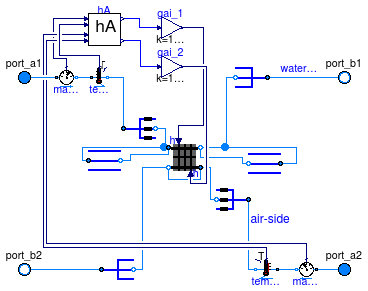
Model of a discretized coil with no water vapor condensation.
The coil consists of nReg registers
that are perpendicular to the air flow path. Each register consists of nPipPar
parallel pipes, and each pipe can be divided into nPipSeg pipe segments along
the pipe length. Thus, the smallest element of the coil consists of a pipe
segment. Each pipe segment is modeled by an instance of
Buildings.Fluid.HeatExchangers.BaseClasses.HexElement.
Each element has a state variable for the metal. Depending
on the value of the boolean parameters steadyState_1 and
steadyState_2, the fluid states are modeled dynamically or in steady
state.
If the parameter steadyStateDuctConnection is set the false, then
a mixing volume of length dl is added to the duct connection. This can
help reducing the dimension of the nonlinear system of equations.
The convective heat transfer coefficients can, for each fluid individually, be computed as a function of the flow rate and/or the temperature, or assigned to a constant. This computation is done using an instance of Buildings.Fluid.HeatExchangers.BaseClasses.HADryCoil.
In this model, the water (or liquid) flow path
needs to be connected to port_a1 and port_b1, and
the air flow path need to be connected to the other two ports.
To model humidity condensation, use the model Buildings.Fluid.HeatExchangers.WetCoilDiscretized instead of this model, as this model computes only sensible heat transfer.
Extends from Fluid.Interfaces.PartialFourPortInterface (Partial model transporting fluid between two ports without storing mass or energy), Buildings.Fluid.Interfaces.FourPortFlowResistanceParameters (Parameters for flow resistance for models with four ports).
| Type | Name | Default | Description |
|---|---|---|---|
| replaceable package Medium1 | PartialMedium | Medium 1 in the component | |
| replaceable package Medium2 | PartialMedium | Medium 2 in the component | |
| Nominal condition | |||
| MassFlowRate | m1_flow_nominal | Nominal mass flow rate [kg/s] | |
| MassFlowRate | m2_flow_nominal | Nominal mass flow rate [kg/s] | |
| Pressure | dp1_nominal | Pressure [Pa] | |
| Pressure | dp2_nominal | Pressure [Pa] | |
| ThermalConductance | UA_nominal | Thermal conductance at nominal flow, used to compute heat capacity [W/K] | |
| Time | tau1 | 20 | Time constant at nominal flow for medium 1 [s] |
| Time | tau2 | 1 | Time constant at nominal flow for medium 2 [s] |
| Time | tau_m | 20 | Time constant of metal at nominal UA value [s] |
| Initialization | |||
| MassFlowRate | m1_flow.start | 0 | Mass flow rate from port_a1 to port_b1 (m1_flow > 0 is design flow direction) [kg/s] |
| Pressure | dp1.start | 0 | Pressure difference between port_a1 and port_b1 [Pa] |
| MassFlowRate | m2_flow.start | 0 | Mass flow rate from port_a2 to port_b2 (m2_flow > 0 is design flow direction) [kg/s] |
| Pressure | dp2.start | 0 | Pressure difference between port_a2 and port_b2 [Pa] |
| MassFlowRate | mStart_flow_a1 | m1_flow_nominal | Guess value for mass flow rate at port_a1 [kg/s] |
| MassFlowRate | mStart_flow_a2 | m2_flow_nominal | Guess value for mass flow rate at port_a2 [kg/s] |
| Geometry | |||
| Integer | nReg | 2 | Number of registers |
| Integer | nPipPar | 3 | Number of parallel pipes in each register |
| Integer | nPipSeg | 4 | Number of pipe segments per register used for discretization |
| Length | dh1 | 0.025 | Hydraulic diameter for a single pipe [m] |
| Length | dh2 | 1 | Hydraulic diameter for duct [m] |
| Assumptions | |||
| Boolean | allowFlowReversal1 | system.allowFlowReversal | = true to allow flow reversal in medium 1, false restricts to design direction (port_a -> port_b) |
| Boolean | allowFlowReversal2 | system.allowFlowReversal | = true to allow flow reversal in medium 2, false restricts to design direction (port_a -> port_b) |
| Advanced | |||
| Initialization | |||
| SpecificEnthalpy | h_outflow_a1_start | Medium1.h_default | Start value for enthalpy flowing out of port a1 [J/kg] |
| SpecificEnthalpy | h_outflow_b1_start | Medium1.h_default | Start value for enthalpy flowing out of port b1 [J/kg] |
| SpecificEnthalpy | h_outflow_a2_start | Medium2.h_default | Start value for enthalpy flowing out of port a2 [J/kg] |
| SpecificEnthalpy | h_outflow_b2_start | Medium2.h_default | Start value for enthalpy flowing out of port b2 [J/kg] |
| MassFlowRate | m1_flow_small | 1E-4*abs(m1_flow_nominal) | Small mass flow rate for regularization of zero flow [kg/s] |
| MassFlowRate | m2_flow_small | 1E-4*abs(m2_flow_nominal) | Small mass flow rate for regularization of zero flow [kg/s] |
| Boolean | homotopyInitialization | true | = true, use homotopy method |
| Boolean | use_dh1 | false | Set to true to specify hydraulic diameter for pipe pressure drop |
| Boolean | use_dh2 | false | Set to true to specify hydraulic diameter for duct pressure drop) |
| Real | ReC_1 | 4000 | Reynolds number where transition to turbulent starts inside pipes |
| Real | ReC_2 | 4000 | Reynolds number where transition to turbulent starts inside ducts |
| Diagnostics | |||
| Boolean | show_T | false | = true, if actual temperature at port is computed |
| Flow resistance | |||
| Medium 1 | |||
| Boolean | computeFlowResistance1 | true | =true, compute flow resistance. Set to false to assume no friction |
| Boolean | from_dp1 | false | = true, use m_flow = f(dp) else dp = f(m_flow) |
| Boolean | linearizeFlowResistance1 | false | = true, use linear relation between m_flow and dp for any flow rate |
| Real | deltaM1 | 0.1 | Fraction of nominal flow rate where flow transitions to laminar |
| Medium 2 | |||
| Boolean | computeFlowResistance2 | true | =true, compute flow resistance. Set to false to assume no friction |
| Boolean | from_dp2 | false | = true, use m_flow = f(dp) else dp = f(m_flow) |
| Boolean | linearizeFlowResistance2 | false | = true, use linear relation between m_flow and dp for any flow rate |
| Real | deltaM2 | 0.1 | Fraction of nominal flow rate where flow transitions to laminar |
| Dynamics | |||
| Equations | |||
| Dynamics | energyDynamics1 | Modelica.Fluid.Types.Dynamic... | Default formulation of energy balances for volume 1 |
| Dynamics | energyDynamics2 | Modelica.Fluid.Types.Dynamic... | Default formulation of energy balances for volume 2 |
| Dynamics | ductConnectionDynamics | Modelica.Fluid.Types.Dynamic... | Default formulation of energy balances for duct connection |
| Length | dl | 0.3 | Length of mixing volume for duct connection [m] |
| Heat transfer | |||
| Boolean | waterSideFlowDependent | false | Set to false to make water-side hA independent of mass flow rate |
| Boolean | airSideFlowDependent | false | Set to false to make air-side hA independent of mass flow rate |
| Boolean | waterSideTemperatureDependent | false | Set to false to make water-side hA independent of temperature |
| Type | Name | Description |
|---|---|---|
| FluidPort_a | port_a1 | Fluid connector a1 (positive design flow direction is from port_a1 to port_b1) |
| FluidPort_b | port_b1 | Fluid connector b1 (positive design flow direction is from port_a1 to port_b1) |
| FluidPort_a | port_a2 | Fluid connector a2 (positive design flow direction is from port_a2 to port_b2) |
| FluidPort_b | port_b2 | Fluid connector b2 (positive design flow direction is from port_a2 to port_b2) |
model DryCoilDiscretized
  "Coil with discretization along the flow paths and no humidity condensation"
  extends Fluid.Interfaces.PartialFourPortInterface(show_T=false);
  extends Buildings.Fluid.Interfaces.FourPortFlowResistanceParameters(
    final computeFlowResistance1=true,
    final computeFlowResistance2=true,
    from_dp1 = false,
    from_dp2 = false);

  parameter Modelica.SIunits.ThermalConductance UA_nominal(min=0)
    "Thermal conductance at nominal flow, used to compute heat capacity";
  parameter Integer nReg(min=2)=2 "Number of registers";
  parameter Integer nPipPar(min=1) = 3
    "Number of parallel pipes in each register";
  parameter Integer nPipSeg(min=1) = 4
    "Number of pipe segments per register used for discretization";
  parameter Boolean use_dh1 = false
    "Set to true to specify hydraulic diameter for pipe pressure drop";
  parameter Boolean use_dh2 = false
    "Set to true to specify hydraulic diameter for duct pressure drop)";

  parameter Modelica.Fluid.Types.Dynamics energyDynamics1=
    Modelica.Fluid.Types.Dynamics.DynamicFreeInitial
    "Default formulation of energy balances for volume 1";
  parameter Modelica.Fluid.Types.Dynamics energyDynamics2=
    Modelica.Fluid.Types.Dynamics.DynamicFreeInitial
    "Default formulation of energy balances for volume 2";

  Buildings.Fluid.HeatExchangers.BaseClasses.CoilRegister hexReg[nReg](
    redeclare each package Medium1 = Medium1,
    redeclare each package Medium2 = Medium2,
    each final allowFlowReversal1=allowFlowReversal1,
    each final allowFlowReversal2=allowFlowReversal2,
    each final nPipPar=nPipPar,
    each final nPipSeg=nPipSeg,
    each final m1_flow_nominal=m1_flow_nominal/nPipPar,
    each final m2_flow_nominal=m1_flow_nominal/nPipPar/nPipSeg,
    each tau1=tau1,
    each tau2=tau2,
    each tau_m=tau_m,
    each final energyDynamics1=energyDynamics1,
    each final energyDynamics2=energyDynamics2,
    each from_dp1=from_dp1,
    each linearizeFlowResistance1=linearizeFlowResistance1,
    each deltaM1=deltaM1,
    each from_dp2=from_dp2,
    each linearizeFlowResistance2=linearizeFlowResistance2,
    each deltaM2=deltaM2,
    each dp1_nominal=0,
    each dp2_nominal=0,
    each final UA_nominal=UA_nominal/nReg) "Heat exchanger register";
  Buildings.Fluid.HeatExchangers.BaseClasses.PipeManifoldFixedResistance
    pipMan_a(
    redeclare package Medium = Medium1,
    final nPipPar=nPipPar,
    final m_flow_nominal=m1_flow_nominal,
    final dp_nominal=dp1_nominal,
    final dh=dh1,
    final ReC=ReC_1,
    final mStart_flow_a=mStart_flow_a1,
    final linearized=linearizeFlowResistance1,
    final use_dh=use_dh1,
    final deltaM=deltaM1,
    final from_dp=from_dp1,
    final allowFlowReversal=allowFlowReversal1) "Pipe manifold at port a";
  Buildings.Fluid.HeatExchangers.BaseClasses.PipeManifoldNoResistance pipMan_b(
    redeclare package Medium = Medium1,
    final nPipPar=nPipPar,
    final mStart_flow_a=-mStart_flow_a1,
    final allowFlowReversal=allowFlowReversal1) "Pipe manifold at port b";
  Buildings.Fluid.HeatExchangers.BaseClasses.DuctManifoldNoResistance ducMan_b(
    redeclare package Medium = Medium2,
    final nPipPar=nPipPar,
    final nPipSeg=nPipSeg,
    final mStart_flow_a=-mStart_flow_a2,
    final allowFlowReversal=allowFlowReversal2) "Duct manifold at port b";
  Buildings.Fluid.HeatExchangers.BaseClasses.DuctManifoldFixedResistance
    ducMan_a(
    redeclare package Medium = Medium2,
    final nPipPar = nPipPar,
    final nPipSeg = nPipSeg,
    final m_flow_nominal=m2_flow_nominal,
    final dp_nominal=dp2_nominal,
    final dh=dh2,
    final ReC=ReC_2,
    final dl=dl,
    final mStart_flow_a=mStart_flow_a2,
    final linearized=linearizeFlowResistance2,
    final use_dh=use_dh2,
    final deltaM=deltaM2,
    final from_dp=from_dp2,
    final allowFlowReversal=allowFlowReversal2,
    final energyDynamics=ductConnectionDynamics) "Duct manifold at port a";
public
  parameter Modelica.SIunits.Length dh1=0.025
    "Hydraulic diameter for a single pipe";
  parameter Real ReC_1=4000
    "Reynolds number where transition to turbulent starts inside pipes";
  parameter Real ReC_2=4000
    "Reynolds number where transition to turbulent starts inside ducts";
  parameter Modelica.SIunits.MassFlowRate m1_flow_nominal
    "Mass flow rate at port_a1 for all pipes";
  parameter Modelica.SIunits.Length dh2=1 "Hydraulic diameter for duct";
  Modelica.SIunits.HeatFlowRate Q1_flow
    "Heat transfered from solid into medium 1";
  Modelica.SIunits.HeatFlowRate Q2_flow
    "Heat transfered from solid into medium 2";
  parameter Modelica.SIunits.Time tau1=20
    "Time constant at nominal flow for medium 1";
  parameter Modelica.SIunits.Time tau2=1
    "Time constant at nominal flow for medium 2";
  parameter Modelica.SIunits.Time tau_m=20
    "Time constant of metal at nominal UA value";

protected
  BaseClasses.CoilHeader hea1[div(nReg,2)](
      redeclare each final package Medium = Medium1,
      each final nPipPar = nPipPar,
      each final mStart_flow_a=mStart_flow_a1,
      each allowFlowReversal=allowFlowReversal1) if
      nReg > 1 "Pipe header to redirect flow into next register";
  BaseClasses.CoilHeader hea2[div(nReg,2)-1](
      redeclare each final package Medium = Medium1,
      each final nPipPar = nPipPar,
      each final mStart_flow_a=mStart_flow_a1,
      each allowFlowReversal=allowFlowReversal1) if
      nReg > 2 "Pipe header to redirect flow into next register";
  Modelica.Blocks.Math.Gain gai_1(k=1/nReg)
    "Gain medium-side 1 to take discretization into account";
  Modelica.Blocks.Math.Gain gai_2(k=1/nReg)
    "Gain medium-side 2 to take discretization into account";
public
  parameter Boolean waterSideFlowDependent = false
    "Set to false to make water-side hA independent of mass flow rate";
  parameter Boolean airSideFlowDependent = false
    "Set to false to make air-side hA independent of mass flow rate";
  parameter Boolean waterSideTemperatureDependent = false
    "Set to false to make water-side hA independent of temperature";
  constant Boolean airSideTemperatureDependent = false
    "Set to false to make air-side hA independent of temperature";
  BaseClasses.HADryCoil hA(
    final UA_nominal=UA_nominal,
    final m_flow_nominal_a=m2_flow_nominal,
    final m_flow_nominal_w=m1_flow_nominal,
    final waterSideTemperatureDependent=waterSideTemperatureDependent,
    final waterSideFlowDependent=waterSideFlowDependent,
    final airSideTemperatureDependent=airSideTemperatureDependent,
    final airSideFlowDependent=airSideFlowDependent)
    "Model for convective heat transfer coefficient";
protected
  constant Boolean allowCondensation = false
    "Set to false to compute sensible heat transfer only";

protected
  Buildings.Fluid.Sensors.TemperatureTwoPort temSen_1(
                                              redeclare package Medium =
        Medium1,
    final allowFlowReversal=allowFlowReversal1,
    m_flow_nominal=m1_flow_nominal) "Temperature sensor";
  Buildings.Fluid.Sensors.MassFlowRate masFloSen_1(redeclare package Medium =
        Medium1, final allowFlowReversal=allowFlowReversal1)
    "Mass flow rate sensor";
  Buildings.Fluid.Sensors.TemperatureTwoPort temSen_2(
                                              redeclare package Medium =
        Medium2,
    m_flow_nominal=m2_flow_nominal,
    final allowFlowReversal=allowFlowReversal2) "Temperature sensor";
  Buildings.Fluid.Sensors.MassFlowRate masFloSen_2(redeclare package Medium =
        Medium2, final allowFlowReversal=allowFlowReversal2)
    "Mass flow rate sensor";
public
  parameter Modelica.Fluid.Types.Dynamics ductConnectionDynamics=
    Modelica.Fluid.Types.Dynamics.DynamicFreeInitial
    "Default formulation of energy balances for duct connection";
  parameter Modelica.SIunits.Length dl=0.3
    "Length of mixing volume for duct connection";
  parameter Modelica.SIunits.MassFlowRate mStart_flow_a1=m1_flow_nominal
    "Guess value for mass flow rate at port_a1";
  parameter Modelica.SIunits.MassFlowRate mStart_flow_a2=m2_flow_nominal
    "Guess value for mass flow rate at port_a2";
initial equation
  assert(UA_nominal>0,     "Parameter UA_nominal is negative. Check heat exchanger parameters.");
equation
  Q1_flow = sum(hexReg[i].Q1_flow for i in 1:nReg);
  Q2_flow = sum(hexReg[i].Q2_flow for i in 1:nReg);

  // air stream connections
  for i in 2:nReg loop
    connect(hexReg[i].port_a2, hexReg[i-1].port_b2);
  end for;
  connect(ducMan_a.port_b, hexReg[1].port_a2);
  connect(hexReg[nReg].port_b2, ducMan_b.port_b);
  connect(pipMan_a.port_b, hexReg[1].port_a1);
  connect(hexReg[nReg].port_b1, pipMan_b.port_b);
  connect(pipMan_b.port_a, port_b1);
  connect(ducMan_b.port_a, port_b2);
  for i in 1:2:nReg loop

  // header after first hex register
    connect(hexReg[i].port_b1, hea1[div((i+1),2)].port_a);
    connect(hea1[div((i+1),2)].port_b, hexReg[i+1].port_b1);
  end for;
  // header after 2nd hex register
  for i in 2:2:(nReg-1) loop
    connect(hexReg[i].port_a1, hea2[div(i,2)].port_a);
    connect(hea2[div(i,2)].port_b, hexReg[i+1].port_a1);
  end for;
  connect(masFloSen_1.m_flow, hA.m1_flow);
  connect(port_a2, masFloSen_2.port_a);
  connect(masFloSen_2.port_b, temSen_2.port_a);
  connect(temSen_2.port_b, ducMan_a.port_a);
  connect(temSen_2.T, hA.T_2);
  connect(masFloSen_2.m_flow, hA.m2_flow);
  connect(hA.hA_1, gai_1.u);
  connect(hA.hA_2, gai_2.u);
  for i in 1:nReg loop
    connect(gai_1.y, hexReg[i].Gc_1);
    connect(gai_2.y, hexReg[i].Gc_2);
  end for;
  connect(port_a1, masFloSen_1.port_a);
  connect(masFloSen_1.port_b, temSen_1.port_a);
  connect(temSen_1.port_b, pipMan_a.port_a);
  connect(temSen_1.T, hA.T_1);
end DryCoilDiscretized;
Buildings.Fluid.HeatExchangers.WetCoilDiscretized
Model of a discretized coil with humidity condensation. This model is identical to Buildings.Fluid.HeatExchangers.DryCoilDiscretized but in addition, the mass transfer from fluid 2 to the metal is computed. The mass transfer is computed using a similarity law between heat and mass transfer, as implemented by the model Buildings.Fluid.HeatExchangers.BaseClasses.MassExchange. See this model for details.
This model can only be used with medium models that
implement the function enthalpyOfLiquid and that contain
an integer variable Water whose value is the element number where
the water vapor is stored in the species concentration vector. Examples for
such media are
Buildings.Media.PerfectGases.MoistAir and
Modelica.Media.Air.MoistAir.
| Type | Name | Default | Description |
|---|---|---|---|
| replaceable package Medium1 | PartialMedium | Medium 1 in the component | |
| replaceable package Medium2 | PartialMedium | Medium 2 in the component | |
| Nominal condition | |||
| MassFlowRate | m1_flow_nominal | Nominal mass flow rate [kg/s] | |
| MassFlowRate | m2_flow_nominal | Nominal mass flow rate [kg/s] | |
| Pressure | dp1_nominal | Pressure [Pa] | |
| Pressure | dp2_nominal | Pressure [Pa] | |
| ThermalConductance | UA_nominal | Thermal conductance at nominal flow, used to compute heat capacity [W/K] | |
| Time | tau1 | 20 | Time constant at nominal flow for medium 1 [s] |
| Time | tau2 | 1 | Time constant at nominal flow for medium 2 [s] |
| Time | tau_m | 20 | Time constant of metal at nominal UA value [s] |
| Initialization | |||
| MassFlowRate | m1_flow.start | 0 | Mass flow rate from port_a1 to port_b1 (m1_flow > 0 is design flow direction) [kg/s] |
| Pressure | dp1.start | 0 | Pressure difference between port_a1 and port_b1 [Pa] |
| MassFlowRate | m2_flow.start | 0 | Mass flow rate from port_a2 to port_b2 (m2_flow > 0 is design flow direction) [kg/s] |
| Pressure | dp2.start | 0 | Pressure difference between port_a2 and port_b2 [Pa] |
| MassFlowRate | mStart_flow_a1 | m1_flow_nominal | Guess value for mass flow rate at port_a1 [kg/s] |
| MassFlowRate | mStart_flow_a2 | m2_flow_nominal | Guess value for mass flow rate at port_a2 [kg/s] |
| Geometry | |||
| Integer | nReg | 2 | Number of registers |
| Integer | nPipPar | 3 | Number of parallel pipes in each register |
| Integer | nPipSeg | 4 | Number of pipe segments per register used for discretization |
| Length | dh1 | 0.025 | Hydraulic diameter for a single pipe [m] |
| Length | dh2 | 1 | Hydraulic diameter for duct [m] |
| Assumptions | |||
| Boolean | allowFlowReversal1 | system.allowFlowReversal | = true to allow flow reversal in medium 1, false restricts to design direction (port_a -> port_b) |
| Boolean | allowFlowReversal2 | system.allowFlowReversal | = true to allow flow reversal in medium 2, false restricts to design direction (port_a -> port_b) |
| Advanced | |||
| Initialization | |||
| SpecificEnthalpy | h_outflow_a1_start | Medium1.h_default | Start value for enthalpy flowing out of port a1 [J/kg] |
| SpecificEnthalpy | h_outflow_b1_start | Medium1.h_default | Start value for enthalpy flowing out of port b1 [J/kg] |
| SpecificEnthalpy | h_outflow_a2_start | Medium2.h_default | Start value for enthalpy flowing out of port a2 [J/kg] |
| SpecificEnthalpy | h_outflow_b2_start | Medium2.h_default | Start value for enthalpy flowing out of port b2 [J/kg] |
| MassFlowRate | m1_flow_small | 1E-4*abs(m1_flow_nominal) | Small mass flow rate for regularization of zero flow [kg/s] |
| MassFlowRate | m2_flow_small | 1E-4*abs(m2_flow_nominal) | Small mass flow rate for regularization of zero flow [kg/s] |
| Boolean | homotopyInitialization | true | = true, use homotopy method |
| Boolean | use_dh1 | false | Set to true to specify hydraulic diameter for pipe pressure drop |
| Boolean | use_dh2 | false | Set to true to specify hydraulic diameter for duct pressure drop) |
| Real | ReC_1 | 4000 | Reynolds number where transition to turbulent starts inside pipes |
| Real | ReC_2 | 4000 | Reynolds number where transition to turbulent starts inside ducts |
| Diagnostics | |||
| Boolean | show_T | false | = true, if actual temperature at port is computed |
| Flow resistance | |||
| Medium 1 | |||
| Boolean | from_dp1 | false | = true, use m_flow = f(dp) else dp = f(m_flow) |
| Boolean | linearizeFlowResistance1 | false | = true, use linear relation between m_flow and dp for any flow rate |
| Real | deltaM1 | 0.1 | Fraction of nominal flow rate where flow transitions to laminar |
| Medium 2 | |||
| Boolean | from_dp2 | false | = true, use m_flow = f(dp) else dp = f(m_flow) |
| Boolean | linearizeFlowResistance2 | false | = true, use linear relation between m_flow and dp for any flow rate |
| Real | deltaM2 | 0.1 | Fraction of nominal flow rate where flow transitions to laminar |
| Dynamics | |||
| Equations | |||
| Dynamics | energyDynamics1 | Modelica.Fluid.Types.Dynamic... | Default formulation of energy balances for volume 1 |
| Dynamics | energyDynamics2 | Modelica.Fluid.Types.Dynamic... | Default formulation of energy balances for volume 2 |
| Dynamics | ductConnectionDynamics | Modelica.Fluid.Types.Dynamic... | Default formulation of energy balances for duct connection |
| Length | dl | 0.3 | Length of mixing volume for duct connection [m] |
| Heat transfer | |||
| Boolean | waterSideFlowDependent | false | Set to false to make water-side hA independent of mass flow rate |
| Boolean | airSideFlowDependent | false | Set to false to make air-side hA independent of mass flow rate |
| Boolean | waterSideTemperatureDependent | false | Set to false to make water-side hA independent of temperature |
| Type | Name | Description |
|---|---|---|
| FluidPort_a | port_a1 | Fluid connector a1 (positive design flow direction is from port_a1 to port_b1) |
| FluidPort_b | port_b1 | Fluid connector b1 (positive design flow direction is from port_a1 to port_b1) |
| FluidPort_a | port_a2 | Fluid connector a2 (positive design flow direction is from port_a2 to port_b2) |
| FluidPort_b | port_b2 | Fluid connector b2 (positive design flow direction is from port_a2 to port_b2) |
model WetCoilDiscretized
  "Coil with discretization along the flow paths and humidity condensation"
  // When replacing the volume, the Medium is constrained so that the enthalpyOfLiquid
  // function is known. Otherwise, checkModel(...) will fail
  extends DryCoilDiscretized(
    each hexReg(redeclare final Buildings.Fluid.HeatExchangers.BaseClasses.HexElementLatent
                                                                    ele[nPipPar, nPipSeg]),
    temSen_1(m_flow_nominal=m1_flow_nominal),
    temSen_2(m_flow_nominal=m2_flow_nominal));

end WetCoilDiscretized;
 Buildings.Fluid.HeatExchangers.HeaterCoolerPrescribed
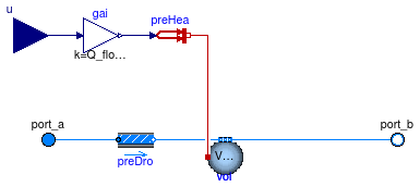
Model for an ideal heater or cooler with prescribed heat flow rate to the medium.
This model adds heat in the amount of Q_flow = u Q_flow_nominal to the medium.
The input signal u and the nominal heat flow rate Q_flow_nominal
can be positive or negative.
| Type | Name | Default | Description |
|---|---|---|---|
| replaceable package Medium | PartialMedium | Medium in the component | |
| HeatFlowRate | Q_flow_nominal | Heat flow rate at u=1, positive for heating [W] | |
| Nominal condition | |||
| MassFlowRate | m_flow_nominal | Nominal mass flow rate [kg/s] | |
| Pressure | dp_nominal | Pressure [Pa] | |
| Initialization | |||
| MassFlowRate | m_flow.start | 0 | Mass flow rate from port_a to port_b (m_flow > 0 is design flow direction) [kg/s] |
| Pressure | dp.start | 0 | Pressure difference between port_a and port_b [Pa] |
| Assumptions | |||
| Boolean | allowFlowReversal | system.allowFlowReversal | = true to allow flow reversal, false restricts to design direction (port_a -> port_b) |
| Advanced | |||
| MassFlowRate | m_flow_small | 1E-4*abs(m_flow_nominal) | Small mass flow rate for regularization of zero flow [kg/s] |
| Boolean | homotopyInitialization | true | = true, use homotopy method |
| Diagnostics | |||
| Boolean | show_T | false | = true, if actual temperature at port is computed |
| Flow resistance | |||
| Boolean | from_dp | false | = true, use m_flow = f(dp) else dp = f(m_flow) |
| Boolean | linearizeFlowResistance | false | = true, use linear relation between m_flow and dp for any flow rate |
| Real | deltaM | 0.1 | Fraction of nominal flow rate where flow transitions to laminar |
| Dynamics | |||
| Nominal condition | |||
| Time | tau | 30 | Time constant at nominal flow (if energyDynamics <> SteadyState) [s] |
| Equations | |||
| Dynamics | energyDynamics | Modelica.Fluid.Types.Dynamic... | Formulation of energy balance |
| Dynamics | massDynamics | energyDynamics | Formulation of mass balance |
| Initialization | |||
| AbsolutePressure | p_start | Medium.p_default | Start value of pressure [Pa] |
| Temperature | T_start | Medium.T_default | Start value of temperature [K] |
| MassFraction | X_start[Medium.nX] | Medium.X_default | Start value of mass fractions m_i/m [kg/kg] |
| ExtraProperty | C_start[Medium.nC] | fill(0, Medium.nC) | Start value of trace substances |
| Type | Name | Description |
|---|---|---|
| FluidPort_a | port_a | Fluid connector a (positive design flow direction is from port_a to port_b) |
| FluidPort_b | port_b | Fluid connector b (positive design flow direction is from port_a to port_b) |
| input RealInput | u | Control input |
model HeaterCoolerPrescribed
  "Heater or cooler with prescribed heat flow rate"
  extends Buildings.Fluid.Interfaces.TwoPortHeatMassExchanger(
    redeclare final Buildings.Fluid.MixingVolumes.MixingVolume vol,
    final showDesignFlowDirection=false);

  parameter Modelica.SIunits.HeatFlowRate Q_flow_nominal
    "Heat flow rate at u=1, positive for heating";
  Modelica.Blocks.Interfaces.RealInput u "Control input";
protected
  Modelica.Thermal.HeatTransfer.Sources.PrescribedHeatFlow preHea
    "Prescribed heat flow";
  Modelica.Blocks.Math.Gain gai(k=Q_flow_nominal) "Gain";
equation
  connect(u, gai.u);
  connect(gai.y, preHea.Q_flow);
  connect(preHea.port, vol.heatPort);
end HeaterCoolerPrescribed;