This package contains base classes that are used to construct the models in Buildings.Fluid.HeatExchangers.
Extends from Modelica.Icons.BasesPackage (Icon for packages containing base classes).| Name | Description |
|---|---|
| Header for a heat exchanger register | |
| Register for a heat exchanger | |
| Manifold for a heat exchanger air duct connection | |
| Duct manifold without resistance | |
| Calculates the hA value for water inside a coil | |
| Sensible convective heat transfer model for air to water coil | |
| Calculates an hA value for natural convection around a cylinder | |
| Element of a heat exchanger | |
| Element of a heat exchanger with humidity condensation of fluid 2 | |
| Block to compute the latent heat transfer based on the Lewis number | |
| Partial model to implement heat exchangers based on effectiveness model | |
| Element of a heat exchanger 2 | |
| Partial manifold for heat exchanger duct connection | |
| Partial heat exchanger duct and pipe manifold | |
| Partial pipe manifold for a heat exchanger | |
| Pipe manifold for a heat exchanger connection | |
| Manifold for heat exchanger register | |
| Calculates the Rayleigh number for a given fluid and characteristic length | |
| Computes the apparatus dewpoint temperature | |
| Returns the dynamic viscosity for water | |
| Computes heat exchanger effectiveness for given capacity flow rates and heat exchanger flow regime | |
| Computes heat exchanger effectiveness for given number of transfer units and heat exchanger flow regime | |
| Returns the isobaric expansion coefficient for water | |
| Computes number of transfer units for given heat exchanger effectiveness and heat exchanger flow regime | |
| Log-mean temperature difference | |
| Returns the Prandtl number for water | |
| Solve f(x, data) for x with given f | |
| Collection of models that illustrate model use and test models |
 Buildings.Fluid.HeatExchangers.BaseClasses.CoilHeader
Header for a heat exchanger coil.
This model connects the flow between its ports without modeling flow friction. Currently, the ports are connected without redistributing the flow. In latter versions, the model may be changed to define different flow reroutings in the coil header.
Extends from Buildings.BaseClasses.BaseIcon (Base icon).
| Type | Name | Default | Description |
|---|---|---|---|
| replaceable package Medium | Modelica.Media.Interfaces.Pa... | Medium in the component | |
| Integer | nPipPar | Number of parallel pipes in each register | |
| Initialization | |||
| MassFlowRate | mStart_flow_a | Guess value for mass flow rate at port_a [kg/s] | |
| Assumptions | |||
| Boolean | allowFlowReversal | system.allowFlowReversal | = true to allow flow reversal, false restricts to design direction (port_a -> port_b) |
| Type | Name | Description |
|---|---|---|
| replaceable package Medium | Medium in the component | |
| FluidPort_a | port_a[nPipPar] | Fluid connector a for medium (positive design flow direction is from port_a to port_b) |
| FluidPort_b | port_b[nPipPar] | Fluid connector b for medium (positive design flow direction is from port_a to port_b) |
model CoilHeader "Header for a heat exchanger register"
  extends Buildings.BaseClasses.BaseIcon;

  outer Modelica.Fluid.System system "System wide properties";

  replaceable package Medium =
      Modelica.Media.Interfaces.PartialMedium "Medium in the component";
  parameter Boolean allowFlowReversal = system.allowFlowReversal
    "= true to allow flow reversal, false restricts to design direction (port_a -> port_b)";

  parameter Integer nPipPar(min=1) "Number of parallel pipes in each register";
  parameter Modelica.SIunits.MassFlowRate mStart_flow_a
    "Guess value for mass flow rate at port_a";

  Modelica.Fluid.Interfaces.FluidPort_a port_a[nPipPar](
        redeclare each final package Medium = Medium,
        each m_flow(start=mStart_flow_a/nPipPar, min=if allowFlowReversal then -Modelica.Constants.inf else 0))
    "Fluid connector a for medium (positive design flow direction is from port_a to port_b)";


  Modelica.Fluid.Interfaces.FluidPort_b port_b[nPipPar](
        redeclare each final package Medium = Medium,
        each m_flow(start=-mStart_flow_a/nPipPar, max=if allowFlowReversal then +Modelica.Constants.inf else 0))
    "Fluid connector b for medium (positive design flow direction is from port_a to port_b)";


equation
  connect(port_a, port_b);
end CoilHeader;
 Buildings.Fluid.HeatExchangers.BaseClasses.CoilRegister
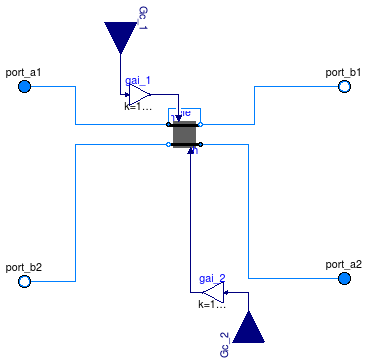
Register of a heat exchanger with dynamics on the fluids and the solid. The register represents one array of pipes that are perpendicular to the air stream. The hA value for both fluids is an input. The driving force for the heat transfer is the temperature difference between the fluid volumes and the solid in each heat exchanger element.
Extends from Buildings.Fluid.Interfaces.FourPortFlowResistanceParameters (Parameters for flow resistance for models with four ports).
| Type | Name | Default | Description |
|---|---|---|---|
| replaceable package Medium1 | Modelica.Media.Interfaces.Pa... | Medium 1 in the component | |
| replaceable package Medium2 | Modelica.Media.Interfaces.Pa... | Medium 2 in the component | |
| Integer | nPipPar | 2 | Number of parallel pipes in each register |
| Integer | nPipSeg | 3 | Number of pipe segments per register used for discretization |
| HexElementSensible | ele[nPipPar, nPipSeg] | redeclare Buildings.Fluid.He... | Element of a heat exchanger |
| Nominal condition | |||
| Pressure | dp1_nominal | Pressure [Pa] | |
| Pressure | dp2_nominal | Pressure [Pa] | |
| ThermalConductance | UA_nominal | Thermal conductance at nominal flow, used to compute time constant [W/K] | |
| MassFlowRate | m1_flow_nominal | Mass flow rate medim 1 [kg/s] | |
| MassFlowRate | m2_flow_nominal | Mass flow rate medium 2 [kg/s] | |
| Time | tau1 | 20 | Time constant at nominal flow for medium 1 [s] |
| Time | tau2 | 1 | Time constant at nominal flow for medium 2 [s] |
| Time | tau_m | 60 | Time constant of metal at nominal UA value [s] |
| Fluid 1 | |||
| Boolean | steadyState_1 | false | Set to true for steady state model for fluid 1 |
| Fluid 2 | |||
| Boolean | steadyState_2 | false | Set to true for steady state model for fluid 2 |
| Flow resistance | |||
| Medium 1 | |||
| Boolean | computeFlowResistance1 | true | =true, compute flow resistance. Set to false to assume no friction |
| Boolean | from_dp1 | false | = true, use m_flow = f(dp) else dp = f(m_flow) |
| Boolean | linearizeFlowResistance1 | false | = true, use linear relation between m_flow and dp for any flow rate |
| Real | deltaM1 | 0.1 | Fraction of nominal flow rate where flow transitions to laminar |
| Medium 2 | |||
| Boolean | computeFlowResistance2 | true | =true, compute flow resistance. Set to false to assume no friction |
| Boolean | from_dp2 | false | = true, use m_flow = f(dp) else dp = f(m_flow) |
| Boolean | linearizeFlowResistance2 | false | = true, use linear relation between m_flow and dp for any flow rate |
| Real | deltaM2 | 0.1 | Fraction of nominal flow rate where flow transitions to laminar |
| Assumptions | |||
| Boolean | allowFlowReversal1 | system.allowFlowReversal | = true to allow flow reversal in medium 1, false restricts to design direction (port_a -> port_b) |
| Boolean | allowFlowReversal2 | system.allowFlowReversal | = true to allow flow reversal in medium 2, false restricts to design direction (port_a -> port_b) |
| Dynamics | |||
| Equations | |||
| Dynamics | energyDynamics1 | Modelica.Fluid.Types.Dynamic... | Default formulation of energy balances for volume 1 |
| Dynamics | energyDynamics2 | Modelica.Fluid.Types.Dynamic... | Default formulation of energy balances for volume 2 |
| Type | Name | Description |
|---|---|---|
| replaceable package Medium1 | Medium 1 in the component | |
| replaceable package Medium2 | Medium 2 in the component | |
| FluidPort_a | port_a1[nPipPar] | Fluid connector a for medium 1 (positive design flow direction is from port_a1 to port_b1) |
| FluidPort_b | port_b1[nPipPar] | Fluid connector b for medium 1 (positive design flow direction is from port_a to port_b) |
| FluidPort_a | port_a2[nPipPar, nPipSeg] | Fluid connector a for medium 2 (positive design flow direction is from port_a2 to port_b2) |
| FluidPort_b | port_b2[nPipPar, nPipSeg] | Fluid connector b for medium 2 (positive design flow direction is from port_a to port_b) |
| input RealInput | Gc_2 | Signal representing the convective thermal conductance medium 2 in [W/K] |
| input RealInput | Gc_1 | Signal representing the convective thermal conductance medium 1 in [W/K] |
model CoilRegister "Register for a heat exchanger"
  import Modelica.Constants;
  extends Buildings.Fluid.Interfaces.FourPortFlowResistanceParameters(
     final computeFlowResistance1=true, final computeFlowResistance2=true);
  replaceable package Medium1 =
      Modelica.Media.Interfaces.PartialMedium "Medium 1 in the component";
  replaceable package Medium2 =
      Modelica.Media.Interfaces.PartialMedium "Medium 2 in the component";
  outer Modelica.Fluid.System system "System wide properties";

  parameter Boolean allowFlowReversal1 = system.allowFlowReversal
    "= true to allow flow reversal in medium 1, false restricts to design direction (port_a -> port_b)";
  parameter Boolean allowFlowReversal2 = system.allowFlowReversal
    "= true to allow flow reversal in medium 2, false restricts to design direction (port_a -> port_b)";

  parameter Integer nPipPar(min=1)=2
    "Number of parallel pipes in each register";
  parameter Integer nPipSeg(min=1)=3
    "Number of pipe segments per register used for discretization";
  final parameter Integer nEle = nPipPar * nPipSeg
    "Number of heat exchanger elements";

  replaceable Buildings.Fluid.HeatExchangers.BaseClasses.HexElementSensible ele[nPipPar, nPipSeg]
    constrainedby Buildings.Fluid.HeatExchangers.BaseClasses.PartialHexElement(
    redeclare each package Medium1 = Medium1,
    redeclare each package Medium2 = Medium2,
    each allowFlowReversal1=allowFlowReversal1,
    each allowFlowReversal2=allowFlowReversal2,
    each tau1=tau1/nPipSeg,
    each m1_flow_nominal=m1_flow_nominal/nPipPar,
    each tau2=tau2,
    each m2_flow_nominal=m2_flow_nominal/nPipPar/nPipSeg,
    each tau_m=tau_m,
    each UA_nominal=UA_nominal/nPipPar/nPipSeg,
    each energyDynamics1=energyDynamics1,
    each energyDynamics2=energyDynamics2,
    each from_dp1=from_dp1,
    each linearizeFlowResistance1=linearizeFlowResistance1,
    each deltaM1=deltaM1,
    each from_dp2=from_dp2,
    each linearizeFlowResistance2=linearizeFlowResistance2,
    each deltaM2=deltaM2,
    each dp1_nominal=dp1_nominal,
    each dp2_nominal=dp2_nominal) "Element of a heat exchanger";

  Modelica.Fluid.Interfaces.FluidPort_a[nPipPar] port_a1(
        redeclare each package Medium = Medium1,
        each m_flow(start=0, min=if allowFlowReversal1 then -Constants.inf else 0))
    "Fluid connector a for medium 1 (positive design flow direction is from port_a1 to port_b1)";
  Modelica.Fluid.Interfaces.FluidPort_b[nPipPar] port_b1(
        redeclare each package Medium = Medium1,
        each m_flow(start=0, max=if allowFlowReversal1 then +Constants.inf else 0))
    "Fluid connector b for medium 1 (positive design flow direction is from port_a to port_b)";
  Modelica.Fluid.Interfaces.FluidPort_a[nPipPar,nPipSeg] port_a2(
        redeclare each package Medium = Medium2,
        each m_flow(start=0, min=if allowFlowReversal2 then -Constants.inf else 0))
    "Fluid connector a for medium 2 (positive design flow direction is from port_a2 to port_b2)";
  Modelica.Fluid.Interfaces.FluidPort_b[nPipPar,nPipSeg] port_b2(
        redeclare each package Medium = Medium2,
        each m_flow(start=0, max=if allowFlowReversal2 then +Constants.inf else 0))
    "Fluid connector b for medium 2 (positive design flow direction is from port_a to port_b)";


  parameter Modelica.SIunits.ThermalConductance UA_nominal
    "Thermal conductance at nominal flow, used to compute time constant";

  parameter Modelica.SIunits.MassFlowRate m1_flow_nominal
    "Mass flow rate medim 1";
  parameter Modelica.SIunits.MassFlowRate m2_flow_nominal
    "Mass flow rate medium 2";

  parameter Modelica.SIunits.Time tau1=20
    "Time constant at nominal flow for medium 1";
  parameter Modelica.SIunits.Time tau2=1
    "Time constant at nominal flow for medium 2";
  parameter Boolean steadyState_1=false
    "Set to true for steady state model for fluid 1";
  parameter Boolean steadyState_2=false
    "Set to true for steady state model for fluid 2";
  Modelica.SIunits.HeatFlowRate Q1_flow
    "Heat transfered from solid into medium 1";
  Modelica.SIunits.HeatFlowRate Q2_flow
    "Heat transfered from solid into medium 2";
  parameter Modelica.SIunits.Time tau_m=60
    "Time constant of metal at nominal UA value";

  parameter Modelica.Fluid.Types.Dynamics energyDynamics1=
    Modelica.Fluid.Types.Dynamics.DynamicFreeInitial
    "Default formulation of energy balances for volume 1";
  parameter Modelica.Fluid.Types.Dynamics energyDynamics2=
    Modelica.Fluid.Types.Dynamics.DynamicFreeInitial
    "Default formulation of energy balances for volume 2";
  Modelica.Blocks.Interfaces.RealInput Gc_2
    "Signal representing the convective thermal conductance medium 2 in [W/K]";
  Modelica.Blocks.Interfaces.RealInput Gc_1
    "Signal representing the convective thermal conductance medium 1 in [W/K]";
protected
  Modelica.Blocks.Math.Gain gai_1(k=1/nEle)
    "Gain medium-side 1 to take discretization into account";
  Modelica.Blocks.Math.Gain gai_2(k=1/nEle)
    "Gain medium-side 2 to take discretization into account";
equation
  Q1_flow = sum(ele[i,j].Q1_flow for i in 1:nPipPar, j in 1:nPipSeg);
  Q2_flow = sum(ele[i,j].Q2_flow for i in 1:nPipPar, j in 1:nPipSeg);
  for i in 1:nPipPar loop
    // liquid side (pipes)
    connect(ele[i,1].port_a1,       port_a1[i]);
    connect(ele[i,nPipSeg].port_b1, port_b1[i]);
    for j in 1:nPipSeg-1 loop
      connect(ele[i,j].port_b1, ele[i,j+1].port_a1);
    end for;
    // gas side (duct)                                                                                      //water connections
    for j in 1:nPipSeg loop
      connect(ele[i,j].port_a2, port_a2[i,j]);
      connect(ele[i,j].port_b2, port_b2[i,j]);
    end for;
  end for;

  connect(Gc_1, gai_1.u);
  connect(Gc_2, gai_2.u);
  for i in 1:nPipPar loop

     for j in 1:nPipSeg loop
      connect(gai_1.y, ele[i,j].Gc_1);
      connect(gai_2.y, ele[i,j].Gc_2);
     end for;
  end for;

end CoilRegister;
 Buildings.Fluid.HeatExchangers.BaseClasses.DuctManifoldFixedResistance
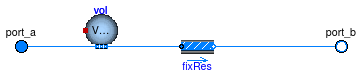
Duct manifold with a fixed flow resistance.
This model causes the flow to be distributed equally into each flow path by using a fixed flow resistance for each flow path.
Extends from PartialDuctManifold (Partial manifold for heat exchanger duct connection).
| Type | Name | Default | Description |
|---|---|---|---|
| replaceable package Medium | PartialMedium | Medium in the component | |
| Integer | nPipPar | Number of parallel pipes in each register | |
| Integer | nPipSeg | Number of pipe segments per register used for discretization | |
| Boolean | use_dh | false | Set to true to specify hydraulic diameter |
| Length | dh | 1 | Hydraulic diameter of duct [m] |
| Real | ReC | 4000 | Reynolds number where transition to turbulent starts |
| Real | deltaM | 0.3 | Fraction of nominal mass flow rate where transition to turbulent occurs |
| Length | dl | 0.3 | Length of mixing volume [m] |
| Initialization | |||
| MassFlowRate | mStart_flow_a | Guess value for mass flow rate at port_a [kg/s] | |
| Nominal Condition | |||
| MassFlowRate | m_flow_nominal | Mass flow rate at port_a [kg/s] | |
| Pressure | dp_nominal | Pressure [Pa] | |
| Assumptions | |||
| Boolean | allowFlowReversal | system.allowFlowReversal | = true to allow flow reversal, false restricts to design direction (port_a -> port_b) |
| Advanced | |||
| Boolean | linearized | false | = true, use linear relation between m_flow and dp for any flow rate |
| Boolean | from_dp | false | = true, use m_flow = f(dp) else dp = f(m_flow) |
| Dynamics | |||
| Equations | |||
| Dynamics | energyDynamics | Modelica.Fluid.Types.Dynamic... | Default formulation of energy balances for volume |
| Type | Name | Description |
|---|---|---|
| FluidPort_a | port_a | Fluid connector a for medium (positive design flow direction is from port_a to port_b) |
| FluidPort_b | port_b[nPipPar, nPipSeg] | Fluid connector b for medium (positive design flow direction is from port_a to port_b) |
model DuctManifoldFixedResistance
  "Manifold for a heat exchanger air duct connection"
  extends PartialDuctManifold;

  parameter Boolean use_dh = false "Set to true to specify hydraulic diameter";

  parameter Modelica.SIunits.MassFlowRate m_flow_nominal
    "Mass flow rate at port_a";
  parameter Modelica.SIunits.Pressure dp_nominal(min=0) "Pressure";
  parameter Modelica.SIunits.Length dh=1 "Hydraulic diameter of duct";
  parameter Real ReC=4000
    "Reynolds number where transition to turbulent starts";
  parameter Boolean linearized = false
    "= true, use linear relation between m_flow and dp for any flow rate";
  parameter Real deltaM(min=0) = 0.3
    "Fraction of nominal mass flow rate where transition to turbulent occurs";
  parameter Boolean from_dp = false
    "= true, use m_flow = f(dp) else dp = f(m_flow)";

  Fluid.FixedResistances.FixedResistanceDpM[nPipPar,nPipSeg] fixRes(
    redeclare each package Medium = Medium,
    each m_flow_nominal=m_flow_nominal/nPipPar/nPipSeg,
    each m_flow(start=mStart_flow_a/nPipPar/nPipSeg),
    each dp_nominal=dp_nominal,
    each dh=dh/sqrt(nPipPar*nPipSeg),
    each from_dp=from_dp,
    each deltaM=deltaM,
    each ReC=ReC,
    each use_dh=use_dh,
    each linearized=linearized) "Fixed resistance for each duct";
  parameter Modelica.SIunits.Length dl = 0.3 "Length of mixing volume";
  Fluid.MixingVolumes.MixingVolume vol(redeclare package Medium = Medium,
    final V=dh*dh*dl,
    final nPorts=1+nPipPar*nPipSeg,
    final energyDynamics=energyDynamics,
    final massDynamics=energyDynamics,
    m_flow_nominal=m_flow_nominal);
  parameter Modelica.Fluid.Types.Dynamics energyDynamics=
    Modelica.Fluid.Types.Dynamics.DynamicFreeInitial
    "Default formulation of energy balances for volume";
equation
  for i in 1:nPipPar loop
    for j in 1:nPipSeg loop
      connect(vol.ports[1+(i-1)*nPipSeg+j], fixRes[i, j].port_a);
    end for;
  end for;

  connect(port_a, vol.ports[1]);
  connect(fixRes.port_b, port_b);
end DuctManifoldFixedResistance;
 Buildings.Fluid.HeatExchangers.BaseClasses.DuctManifoldNoResistance
Duct manifold without flow resistance.
This model connects the flows between the ports without modeling flow friction. The model is used in conjunction with a manifold which contains pressure drop elements and that is added to the other side of the heat exchanger registers.
Extends from PartialDuctManifold (Partial manifold for heat exchanger duct connection).
| Type | Name | Default | Description |
|---|---|---|---|
| replaceable package Medium | PartialMedium | Medium in the component | |
| Integer | nPipPar | Number of parallel pipes in each register | |
| Integer | nPipSeg | Number of pipe segments per register used for discretization | |
| Initialization | |||
| MassFlowRate | mStart_flow_a | Guess value for mass flow rate at port_a [kg/s] | |
| Assumptions | |||
| Boolean | allowFlowReversal | system.allowFlowReversal | = true to allow flow reversal, false restricts to design direction (port_a -> port_b) |
| Type | Name | Description |
|---|---|---|
| FluidPort_a | port_a | Fluid connector a for medium (positive design flow direction is from port_a to port_b) |
| FluidPort_b | port_b[nPipPar, nPipSeg] | Fluid connector b for medium (positive design flow direction is from port_a to port_b) |
model DuctManifoldNoResistance "Duct manifold without resistance"
  extends PartialDuctManifold;

equation
  for i in 1:nPipPar loop
    for j in 1:nPipSeg loop
    connect(port_a, port_b[i, j]);
    end for;
  end for;
end DuctManifoldNoResistance;
 Buildings.Fluid.HeatExchangers.BaseClasses.HACoilInside
Model for convective heat transfer coefficients inside a coil. Optionally, the convective heat transfer coefficient can be computed as a function of temperature and mass flow rate.
Extends from Buildings.BaseClasses.BaseIcon (Base icon).
| Type | Name | Default | Description |
|---|---|---|---|
| Real | n | 0.85 | Water-side exponent for convective heat transfer coefficient, h proportional to m_flow^n |
| Nominal condition | |||
| MassFlowRate | m_flow_nominal | Water mass flow rate [kg/s] | |
| ThermalConductance | hA_nominal | Convective heat transfer coefficient [W/K] | |
| Temperature | T_nominal | Modelica.SIunits.Conversions... | Nominal water temperature [K] |
| Advanced | |||
| Modeling detail | |||
| Boolean | flowDependent | true | Set to false to make hA independent of mass flow rate |
| Boolean | temperatureDependent | true | Set to false to make hA independent of temperature |
| Type | Name | Description |
|---|---|---|
| input RealInput | m_flow | Mass flow rate [kg/s] |
| input RealInput | T | Temperature [K] |
| output RealOutput | hA | Inside convective heat transfer [W/K] |
model HACoilInside "Calculates the hA value for water inside a coil" extends Buildings.BaseClasses.BaseIcon; parameter Modelica.SIunits.MassFlowRate m_flow_nominal "Water mass flow rate";Modelica.Blocks.Interfaces.RealInput m_flow(unit="kg/s") "Mass flow rate"; Modelica.Blocks.Interfaces.RealInput T(unit="K") "Temperature"; Modelica.Blocks.Interfaces.RealOutput hA(unit="W/K") "Inside convective heat transfer"; parameter Modelica.SIunits.ThermalConductance hA_nominal(min=0) "Convective heat transfer coefficient"; parameter Real n(min=0, max=1)=0.85 "Water-side exponent for convective heat transfer coefficient, h proportional to m_flow^n"; parameter Modelica.SIunits.Temperature T_nominal= Modelica.SIunits.Conversions.from_degC(20) "Nominal water temperature"; parameter Boolean flowDependent=true "Set to false to make hA independent of mass flow rate"; parameter Boolean temperatureDependent = true "Set to false to make hA independent of temperature"; protected Real x(min=0) "Factor for temperature dependent variation of heat transfer coefficient"; parameter Real s(min=0, fixed=false) "Coefficient for temperature dependence of heat transfer coefficient"; Real fm "Fraction of actual to nominal mass flow rate"; initial equation s = if temperatureDependent then 0.014/(1+0.014*Modelica.SIunits.Conversions.to_degC(T_nominal)) else 1; equation fm = if flowDependent then m_flow / m_flow_nominal else 1; x = if temperatureDependent then 1 + s * (T-T_nominal) else 1; if flowDependent and temperatureDependent then hA = x * hA_nominal * Buildings.Utilities.Math.Functions.regNonZeroPower(fm, n, 0.1); elseif flowDependent then hA = hA_nominal * Buildings.Utilities.Math.Functions.regNonZeroPower(fm, n, 0.1); elseif temperatureDependent then hA = x * hA_nominal; else hA = hA_nominal; end if;end HACoilInside;
 Buildings.Fluid.HeatExchangers.BaseClasses.HADryCoil
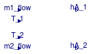
Model for sensible convective heat transfer coefficients for an air to water coil.
This model computes the convective heat transfer coefficient for an air to water coil. The parameters allow a user to enable or disable, individually for each medium, the mass flow and/or the temperature dependence of the convective heat transfer coefficients. For a detailed explanation of the equation, see the references below.
| Type | Name | Default | Description |
|---|---|---|---|
| Real | n_w | 0.85 | Water-side exponent for convective heat transfer coefficient, h~m_flow^n |
| Real | n_a | 0.8 | Air-side exponent for convective heat transfer coefficient, h~m_flow^n |
| Nominal condition | |||
| ThermalConductance | UA_nominal | Thermal conductance at nominal flow [W/K] | |
| MassFlowRate | m_flow_nominal_w | Water mass flow rate [kg/s] | |
| MassFlowRate | m_flow_nominal_a | Air mass flow rate [kg/s] | |
| Real | r_nominal | 0.5 | Ratio between air-side and water-side convective heat transfer coefficient |
| ThermalConductance | hA_nominal_w | UA_nominal*(r_nominal + 1)/r... | Water side convective heat transfer coefficient [W/K] |
| ThermalConductance | hA_nominal_a | r_nominal*hA_nominal_w | Air side convective heat transfer coefficient, including fin resistance [W/K] |
| Temperature | T0_w | Modelica.SIunits.Conversions... | Water temperature [K] |
| Temperature | T0_a | Modelica.SIunits.Conversions... | Air temperature [K] |
| Advanced | |||
| Modeling detail | |||
| Boolean | waterSideFlowDependent | true | Set to false to make water-side hA independent of mass flow rate |
| Boolean | airSideFlowDependent | true | Set to false to make air-side hA independent of mass flow rate |
| Boolean | waterSideTemperatureDependent | true | Set to false to make water-side hA independent of temperature |
| Boolean | airSideTemperatureDependent | true | Set to false to make air-side hA independent of temperature |
| Type | Name | Description |
|---|---|---|
| input RealInput | m1_flow | Mass flow rate medium 1 |
| input RealInput | m2_flow | Mass flow rate medium 2 |
| input RealInput | T_1 | Temperature medium 1 |
| input RealInput | T_2 | Temperature medium 2 |
| output RealOutput | hA_1 | Convective heat transfer medium 1 |
| output RealOutput | hA_2 | Convective heat transfer medium 2 |
model HADryCoil
  "Sensible convective heat transfer model for air to water coil"
  extends Buildings.BaseClasses.BaseIcon;
  parameter Modelica.SIunits.ThermalConductance UA_nominal(min=0)
    "Thermal conductance at nominal flow";

  parameter Modelica.SIunits.MassFlowRate m_flow_nominal_w
    "Water mass flow rate";
  parameter Modelica.SIunits.MassFlowRate m_flow_nominal_a "Air mass flow rate";

  Modelica.Blocks.Interfaces.RealInput m1_flow "Mass flow rate medium 1";
  Modelica.Blocks.Interfaces.RealInput m2_flow "Mass flow rate medium 2";
  Modelica.Blocks.Interfaces.RealInput T_1 "Temperature medium 1";
  Modelica.Blocks.Interfaces.RealInput T_2 "Temperature medium 2";

  Modelica.Blocks.Interfaces.RealOutput hA_1
    "Convective heat transfer medium 1";
  Modelica.Blocks.Interfaces.RealOutput hA_2
    "Convective heat transfer medium 2";

  parameter Real r_nominal(min=0)=0.5
    "Ratio between air-side and water-side convective heat transfer coefficient";
  parameter Modelica.SIunits.ThermalConductance hA_nominal_w(min=0)=UA_nominal * (r_nominal+1)/r_nominal
    "Water side convective heat transfer coefficient";
  parameter Modelica.SIunits.ThermalConductance hA_nominal_a(min=0)=r_nominal * hA_nominal_w
    "Air side convective heat transfer coefficient, including fin resistance";
  parameter Real n_w(min=0, max=1)=0.85
    "Water-side exponent for convective heat transfer coefficient, h~m_flow^n";
  parameter Real n_a(min=0, max=1)=0.8
    "Air-side exponent for convective heat transfer coefficient, h~m_flow^n";
  parameter Modelica.SIunits.Temperature T0_w=
          Modelica.SIunits.Conversions.from_degC(20) "Water temperature";
  parameter Modelica.SIunits.Temperature T0_a=
          Modelica.SIunits.Conversions.from_degC(20) "Air temperature";
  parameter Boolean waterSideFlowDependent=true
    "Set to false to make water-side hA independent of mass flow rate";
  parameter Boolean airSideFlowDependent = true
    "Set to false to make air-side hA independent of mass flow rate";
  parameter Boolean waterSideTemperatureDependent = true
    "Set to false to make water-side hA independent of temperature";
  parameter Boolean airSideTemperatureDependent = true
    "Set to false to make air-side hA independent of temperature";
protected
  Real x_a(min=0)
    "Factor for air side temperature dependent variation of heat transfer coefficient";
  Real x_w(min=0)
    "Factor for water side temperature dependent variation of heat transfer coefficient";
  parameter Real s_w(min=0, fixed=false)
    "Coefficient for temperature dependence of water side heat transfer coefficient";
  Real fm_w "Fraction of actual to nominal mass flow rate";
  Real fm_a "Fraction of actual to nominal mass flow rate";
initial equation
  s_w =  if waterSideTemperatureDependent then
            0.014/(1+0.014*Modelica.SIunits.Conversions.to_degC(T0_w)) else
              1;
equation
  fm_w = if waterSideFlowDependent then
              m1_flow / m_flow_nominal_w else 1;
  fm_a = if airSideFlowDependent then
              m2_flow / m_flow_nominal_a else 1;
  x_w = if waterSideTemperatureDependent then
         1 + s_w * (T_1-T0_w) else
              1;
  x_a = if airSideTemperatureDependent then
         1 + 4.769E-3 * (T_2-T0_a) else
              1;
  if waterSideFlowDependent then
    hA_1 = x_w * hA_nominal_w
               * Buildings.Utilities.Math.Functions.regNonZeroPower(fm_w, n_w, 0.1);
  else
    hA_1 = x_w * hA_nominal_w;
  end if;

  if airSideFlowDependent then
    hA_2 = x_a * hA_nominal_a
               * Buildings.Utilities.Math.Functions.regNonZeroPower(fm_a, n_a, 0.1);
  else
    hA_2 = x_a * hA_nominal_a;
  end if;
end HADryCoil;
 Buildings.Fluid.HeatExchangers.BaseClasses.HANaturalCylinder
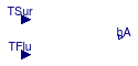
This model calculates the convection coefficient h for natural convection from a cylinder submerged in fluid. h is calcualted using Eq 9.34 from Incropera and DeWitt (1996). Output of the block is the hA value.
The Nusselt number is computed as
NuD = (0.6 + (0.387 RaD(1/6))/(1+(0.559 Pr) (9/16))(8/27))2);
where NuD is the Nusselt number, RaD is the
Rayleigh number and
Pr is the Prandtl number.
This correclation is accurate for RaD less than 1012.
h is then calculated from the Nusselt number. The equation is
h = NuD k/D
where k is the thermal conductivity of the fluid and D is the diameter of the submerged cylinder.
Fundamentals of Heat and Mass Transfer (Fourth Edition), Frank Incropera and David DeWitt, John Wiley and Sons, 1996
Extends from Modelica.Blocks.Interfaces.BlockIcon (Basic graphical layout of input/output block).
| Type | Name | Default | Description |
|---|---|---|---|
| replaceable package Medium | Modelica.Media.Interfaces.Pa... | Partial medium model to be replaced with specific medium | |
| Diameter | ChaLen | Characteristic length of the cylinder [m] | |
| Nominal condition | |||
| ThermalConductance | hA_nominal | Convective heat transfer coefficient [W/K] | |
| Temperature | TFlu_nominal | Fluid temperature at hA_nominal [K] | |
| Temperature | TSur_nominal | Surface temperature at hA_nominal [K] | |
| Type | Name | Description |
|---|---|---|
| replaceable package Medium | Partial medium model to be replaced with specific medium | |
| input RealInput | TSur | Temperature of the external surface of the heat exchanger [K] |
| input RealInput | TFlu | Temperature of the fluid in the heat exchanger [K] |
| output RealOutput | hA | hA-value of the heat exchanger [W/K] |
model HANaturalCylinder
"Calculates an hA value for natural convection around a cylinder"
extends Modelica.Blocks.Interfaces.BlockIcon;
replaceable package Medium = Modelica.Media.Interfaces.PartialMedium
"Partial medium model to be replaced with specific medium";
parameter Modelica.SIunits.Diameter ChaLen
"Characteristic length of the cylinder";
parameter Modelica.SIunits.ThermalConductance hA_nominal(min=0)
"Convective heat transfer coefficient";
parameter Modelica.SIunits.Temperature TFlu_nominal
"Fluid temperature at hA_nominal";
parameter Modelica.SIunits.Temperature TSur_nominal
"Surface temperature at hA_nominal";
Modelica.Blocks.Interfaces.RealInput TSur(unit = "K")
"Temperature of the external surface of the heat exchanger";
Modelica.Blocks.Interfaces.RealInput TFlu(unit = "K")
"Temperature of the fluid in the heat exchanger";
Modelica.Blocks.Interfaces.RealOutput hA(unit = "W/K")
"hA-value of the heat exchanger";
Real h(unit="W/(m2.K)") "Convection coefficient";
protected
parameter Real Gr_nominal(fixed=false) "Grashof number";
parameter Real B_nominal(unit="1/K", fixed=false)
"isobaricExpansionCoefficient";
parameter Real nu_nominal(unit = "m2/s", fixed=false)
"Kinematic viscosity of the medium";
parameter Modelica.SIunits.DynamicViscosity mu_nominal(fixed=false)
"Dynamic viscosity of the medium";
parameter Modelica.SIunits.Density rho_nominal(fixed=false)
"Density of the medium";
parameter Modelica.SIunits.ThermalConductivity k_nominal(fixed=false)
"Thermal conductivity of the fluid";
parameter Real Ra_nominal(fixed=false) "Rayleigh number";
parameter Real Pr_nominal(fixed=false) "Prandlt number";
parameter Real Nusselt_nominal(fixed=false) "Nusselt number";
parameter Real h_nominal(unit="W/(m2.K)", fixed=false)
"Convection coefficient";
parameter Modelica.SIunits.Area A(fixed=false)
"Surface area, deduced from hA_nominal, fluid temperatures and characteristic length";
Modelica.SIunits.ThermalConductivity k "Thermal conductivity of the fluid";
Real Gr "Grashof number";
Real B(unit="1/K") "isobaricExpansionCoefficient";
Real nu(unit = "m2/s") "Kinematic viscosity of the medium";
Modelica.SIunits.DynamicViscosity mu "Dynamic viscosity of the medium";
Modelica.SIunits.Density rho "Density of the medium";
constant Modelica.SIunits.Acceleration g= Modelica.Constants.g_n
"Acceleration due to gravity";
Real Ra "Rayleigh number";
Real Pr "Prandlt number";
Real Nusselt "Nusselt number";
function nusselt
input Modelica.SIunits.ThermalConductivity k "Thermal conductivity";
input Real Pr "Prandlt number";
input Real Ra "Rayleigh number";
output Real Nu(min=0) "Nusselt number";
protected
Real num "Numerator";
Real den "Denominator";
algorithm
num := (0.387*Buildings.Utilities.Math.Functions.smoothMax(Ra,1,0.1)^(1/6));
den := ((1+(0.559/Pr)^(9/16))^(8/27));
Nu := (0.6+num/den)^2;
end nusselt ;
initial equation
// Fluid properties
mu_nominal = Buildings.Fluid.HeatExchangers.BaseClasses.dynamicViscosityWater(
T= 0.5 * (TSur_nominal+TFlu_nominal));
rho_nominal = Medium.density(
Medium.setState_pTX(
p= Medium.p_default,
T= 0.5*(TSur_nominal+TFlu_nominal),
X= Medium.X_default));
Pr_nominal = Buildings.Fluid.HeatExchangers.BaseClasses.prandtlNumberWater(
T= 0.5*(TSur_nominal+TFlu_nominal));
B_nominal = Buildings.Fluid.HeatExchangers.BaseClasses.isobaricExpansionCoefficientWater(
T= 0.5*(TSur_nominal+TFlu_nominal));
nu_nominal = mu_nominal/rho_nominal;
Gr_nominal = Modelica.Constants.g_n * B_nominal * (TSur_nominal -
TFlu_nominal)*ChaLen^3/nu_nominal^2;
Ra_nominal = Gr_nominal*Pr_nominal;
// Convection coefficient
k_nominal = Medium.thermalConductivity(
Medium.setState_pTX(
p= Medium.p_default,
T= 0.5*(TFlu_nominal+TSur_nominal),
X= Medium.X_default));
Nusselt_nominal = nusselt(k=k_nominal, Pr=Pr_nominal, Ra=Ra_nominal);
h_nominal = Nusselt_nominal * k_nominal/ChaLen;
A = hA_nominal / h_nominal;
equation
// Fluid properties
mu = Buildings.Fluid.HeatExchangers.BaseClasses.dynamicViscosityWater(
T= 0.5 * (TSur+TFlu));
rho = Medium.density(
Medium.setState_pTX(
p= Medium.p_default,
T= 0.5*(TSur+TFlu),
X= Medium.X_default));
Pr = Buildings.Fluid.HeatExchangers.BaseClasses.prandtlNumberWater(
T= 0.5*(TSur+TFlu));
B = Buildings.Fluid.HeatExchangers.BaseClasses.isobaricExpansionCoefficientWater(
T= 0.5*(TSur+TFlu));
nu = mu/rho;
Gr = Modelica.Constants.g_n * B * (TSur - TFlu)*ChaLen^3/nu^2;
Ra = Gr*Pr;
// Convection coefficient
k = Medium.thermalConductivity(
Medium.setState_pTX(
p= Medium.p_default,
T= 0.5*(TFlu+TSur),
X= Medium.X_default));
Nusselt = nusselt(k=k, Pr=Pr, Ra=Ra);
h = Nusselt * k/ChaLen;
hA = h*A;
end HANaturalCylinder;
 Buildings.Fluid.HeatExchangers.BaseClasses.HexElementLatent
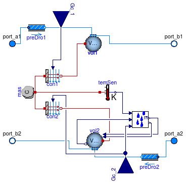
Element of a heat exchanger with humidity condensation of fluid 2 and with dynamics of the fluids and the solid.
See Buildings.Fluid.HeatExchangers.BaseClasses.PartialHexElement for a description of the physics.
Extends from Buildings.Fluid.HeatExchangers.BaseClasses.PartialHexElement (Element of a heat exchanger 2).
| Type | Name | Default | Description |
|---|---|---|---|
| replaceable package Medium1 | PartialMedium | Medium 1 in the component | |
| replaceable package Medium2 | PartialMedium | Medium 2 in the component | |
| HeatCapacity | C | 2*UA_nominal*tau_m | Heat capacity of metal (= cp*m) [J/K] |
| Nominal condition | |||
| MassFlowRate | m1_flow_nominal | Nominal mass flow rate [kg/s] | |
| MassFlowRate | m2_flow_nominal | Nominal mass flow rate [kg/s] | |
| Pressure | dp1_nominal | Pressure [Pa] | |
| Pressure | dp2_nominal | Pressure [Pa] | |
| ThermalConductance | UA_nominal | Thermal conductance at nominal flow, used to compute time constant [W/K] | |
| Time | tau_m | 60 | Time constant of metal at nominal UA value [s] |
| Initialization | |||
| MassFlowRate | m1_flow.start | 0 | Mass flow rate from port_a1 to port_b1 (m1_flow > 0 is design flow direction) [kg/s] |
| Pressure | dp1.start | 0 | Pressure difference between port_a1 and port_b1 [Pa] |
| MassFlowRate | m2_flow.start | 0 | Mass flow rate from port_a2 to port_b2 (m2_flow > 0 is design flow direction) [kg/s] |
| Pressure | dp2.start | 0 | Pressure difference between port_a2 and port_b2 [Pa] |
| Assumptions | |||
| Boolean | allowFlowReversal1 | system.allowFlowReversal | = true to allow flow reversal in medium 1, false restricts to design direction (port_a -> port_b) |
| Boolean | allowFlowReversal2 | system.allowFlowReversal | = true to allow flow reversal in medium 2, false restricts to design direction (port_a -> port_b) |
| Advanced | |||
| MassFlowRate | m1_flow_small | 1E-4*abs(m1_flow_nominal) | Small mass flow rate for regularization of zero flow [kg/s] |
| MassFlowRate | m2_flow_small | 1E-4*abs(m2_flow_nominal) | Small mass flow rate for regularization of zero flow [kg/s] |
| Boolean | homotopyInitialization | true | = true, use homotopy method |
| Diagnostics | |||
| Boolean | show_T | false | = true, if actual temperature at port is computed |
| Flow resistance | |||
| Medium 1 | |||
| Boolean | from_dp1 | false | = true, use m_flow = f(dp) else dp = f(m_flow) |
| Boolean | linearizeFlowResistance1 | false | = true, use linear relation between m_flow and dp for any flow rate |
| Real | deltaM1 | 0.1 | Fraction of nominal flow rate where flow transitions to laminar |
| Medium 2 | |||
| Boolean | from_dp2 | false | = true, use m_flow = f(dp) else dp = f(m_flow) |
| Boolean | linearizeFlowResistance2 | false | = true, use linear relation between m_flow and dp for any flow rate |
| Real | deltaM2 | 0.1 | Fraction of nominal flow rate where flow transitions to laminar |
| Dynamics | |||
| Nominal condition | |||
| Time | tau1 | 30 | Time constant at nominal flow [s] |
| Time | tau2 | 30 | Time constant at nominal flow [s] |
| Equations | |||
| Dynamics | energyDynamics | Modelica.Fluid.Types.Dynamic... | Formulation of energy balance |
| Dynamics | massDynamics | energyDynamics | Formulation of mass balance |
| Dynamics | energyDynamics1 | Modelica.Fluid.Types.Dynamic... | Default formulation of energy balances for volume 1 |
| Dynamics | energyDynamics2 | Modelica.Fluid.Types.Dynamic... | Default formulation of energy balances for volume 2 |
| Initialization | |||
| Medium 1 | |||
| AbsolutePressure | p1_start | Medium1.p_default | Start value of pressure [Pa] |
| Temperature | T1_start | Medium1.T_default | Start value of temperature [K] |
| MassFraction | X1_start[Medium1.nX] | Medium1.X_default | Start value of mass fractions m_i/m [kg/kg] |
| ExtraProperty | C1_start[Medium1.nC] | fill(0, Medium1.nC) | Start value of trace substances |
| ExtraProperty | C1_nominal[Medium1.nC] | fill(1E-2, Medium1.nC) | Nominal value of trace substances. (Set to typical order of magnitude.) |
| Medium 2 | |||
| AbsolutePressure | p2_start | Medium2.p_default | Start value of pressure [Pa] |
| Temperature | T2_start | Medium2.T_default | Start value of temperature [K] |
| MassFraction | X2_start[Medium2.nX] | Medium2.X_default | Start value of mass fractions m_i/m [kg/kg] |
| ExtraProperty | C2_start[Medium2.nC] | fill(0, Medium2.nC) | Start value of trace substances |
| ExtraProperty | C2_nominal[Medium2.nC] | fill(1E-2, Medium2.nC) | Nominal value of trace substances. (Set to typical order of magnitude.) |
| Type | Name | Description |
|---|---|---|
| FluidPort_a | port_a1 | Fluid connector a1 (positive design flow direction is from port_a1 to port_b1) |
| FluidPort_b | port_b1 | Fluid connector b1 (positive design flow direction is from port_a1 to port_b1) |
| FluidPort_a | port_a2 | Fluid connector a2 (positive design flow direction is from port_a2 to port_b2) |
| FluidPort_b | port_b2 | Fluid connector b2 (positive design flow direction is from port_a2 to port_b2) |
| input RealInput | Gc_1 | Signal representing the convective thermal conductance medium 1 in [W/K] |
| input RealInput | Gc_2 | Signal representing the convective thermal conductance medium 2 in [W/K] |
model HexElementLatent "Element of a heat exchanger"
  extends Buildings.Fluid.HeatExchangers.BaseClasses.PartialHexElement(
    redeclare final Buildings.Fluid.MixingVolumes.MixingVolumeMoistAir vol2(
      final energyDynamics=energyDynamics2,
      final massDynamics=energyDynamics2));

  MassExchange masExc(
     redeclare final package Medium=Medium2) "Model for mass exchange";
protected
  Modelica.Thermal.HeatTransfer.Sensors.TemperatureSensor temSen(
    T(final quantity="ThermodynamicTemperature",
      final unit = "K", displayUnit = "degC", min=0))
    "Temperature sensor of metal";
equation
  connect(temSen.T, masExc.TSur);
  connect(masExc.mWat_flow, vol2.mWat_flow);
  connect(masExc.TLiq, vol2.TWat);
  connect(vol2.X_w, masExc.XInf);
  connect(mas.port, temSen.port);
  connect(Gc_2, masExc.Gc);
end HexElementLatent;
 Buildings.Fluid.HeatExchangers.BaseClasses.HexElementSensible
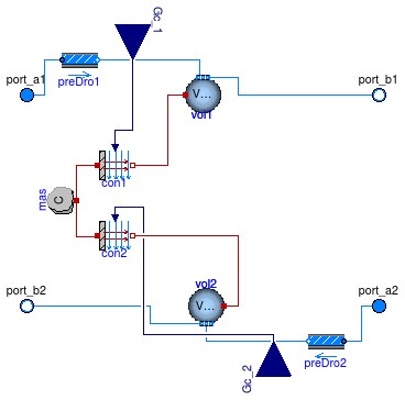
Element of a heat exchanger with humidity condensation and with dynamics of the fluids and the solid.
See Buildings.Fluid.HeatExchangers.BaseClasses.PartialHexElement for a description of the physics.
Extends from Buildings.Fluid.HeatExchangers.BaseClasses.PartialHexElement (Element of a heat exchanger 2).
| Type | Name | Default | Description |
|---|---|---|---|
| replaceable package Medium1 | PartialMedium | Medium 1 in the component | |
| replaceable package Medium2 | PartialMedium | Medium 2 in the component | |
| HeatCapacity | C | 2*UA_nominal*tau_m | Heat capacity of metal (= cp*m) [J/K] |
| Nominal condition | |||
| MassFlowRate | m1_flow_nominal | Nominal mass flow rate [kg/s] | |
| MassFlowRate | m2_flow_nominal | Nominal mass flow rate [kg/s] | |
| Pressure | dp1_nominal | Pressure [Pa] | |
| Pressure | dp2_nominal | Pressure [Pa] | |
| ThermalConductance | UA_nominal | Thermal conductance at nominal flow, used to compute time constant [W/K] | |
| Time | tau_m | 60 | Time constant of metal at nominal UA value [s] |
| Initialization | |||
| MassFlowRate | m1_flow.start | 0 | Mass flow rate from port_a1 to port_b1 (m1_flow > 0 is design flow direction) [kg/s] |
| Pressure | dp1.start | 0 | Pressure difference between port_a1 and port_b1 [Pa] |
| MassFlowRate | m2_flow.start | 0 | Mass flow rate from port_a2 to port_b2 (m2_flow > 0 is design flow direction) [kg/s] |
| Pressure | dp2.start | 0 | Pressure difference between port_a2 and port_b2 [Pa] |
| Assumptions | |||
| Boolean | allowFlowReversal1 | system.allowFlowReversal | = true to allow flow reversal in medium 1, false restricts to design direction (port_a -> port_b) |
| Boolean | allowFlowReversal2 | system.allowFlowReversal | = true to allow flow reversal in medium 2, false restricts to design direction (port_a -> port_b) |
| Advanced | |||
| MassFlowRate | m1_flow_small | 1E-4*abs(m1_flow_nominal) | Small mass flow rate for regularization of zero flow [kg/s] |
| MassFlowRate | m2_flow_small | 1E-4*abs(m2_flow_nominal) | Small mass flow rate for regularization of zero flow [kg/s] |
| Boolean | homotopyInitialization | true | = true, use homotopy method |
| Diagnostics | |||
| Boolean | show_T | false | = true, if actual temperature at port is computed |
| Flow resistance | |||
| Medium 1 | |||
| Boolean | from_dp1 | false | = true, use m_flow = f(dp) else dp = f(m_flow) |
| Boolean | linearizeFlowResistance1 | false | = true, use linear relation between m_flow and dp for any flow rate |
| Real | deltaM1 | 0.1 | Fraction of nominal flow rate where flow transitions to laminar |
| Medium 2 | |||
| Boolean | from_dp2 | false | = true, use m_flow = f(dp) else dp = f(m_flow) |
| Boolean | linearizeFlowResistance2 | false | = true, use linear relation between m_flow and dp for any flow rate |
| Real | deltaM2 | 0.1 | Fraction of nominal flow rate where flow transitions to laminar |
| Dynamics | |||
| Nominal condition | |||
| Time | tau1 | 30 | Time constant at nominal flow [s] |
| Time | tau2 | 30 | Time constant at nominal flow [s] |
| Equations | |||
| Dynamics | energyDynamics | Modelica.Fluid.Types.Dynamic... | Formulation of energy balance |
| Dynamics | massDynamics | energyDynamics | Formulation of mass balance |
| Dynamics | energyDynamics1 | Modelica.Fluid.Types.Dynamic... | Default formulation of energy balances for volume 1 |
| Dynamics | energyDynamics2 | Modelica.Fluid.Types.Dynamic... | Default formulation of energy balances for volume 2 |
| Initialization | |||
| Medium 1 | |||
| AbsolutePressure | p1_start | Medium1.p_default | Start value of pressure [Pa] |
| Temperature | T1_start | Medium1.T_default | Start value of temperature [K] |
| MassFraction | X1_start[Medium1.nX] | Medium1.X_default | Start value of mass fractions m_i/m [kg/kg] |
| ExtraProperty | C1_start[Medium1.nC] | fill(0, Medium1.nC) | Start value of trace substances |
| ExtraProperty | C1_nominal[Medium1.nC] | fill(1E-2, Medium1.nC) | Nominal value of trace substances. (Set to typical order of magnitude.) |
| Medium 2 | |||
| AbsolutePressure | p2_start | Medium2.p_default | Start value of pressure [Pa] |
| Temperature | T2_start | Medium2.T_default | Start value of temperature [K] |
| MassFraction | X2_start[Medium2.nX] | Medium2.X_default | Start value of mass fractions m_i/m [kg/kg] |
| ExtraProperty | C2_start[Medium2.nC] | fill(0, Medium2.nC) | Start value of trace substances |
| ExtraProperty | C2_nominal[Medium2.nC] | fill(1E-2, Medium2.nC) | Nominal value of trace substances. (Set to typical order of magnitude.) |
| Type | Name | Description |
|---|---|---|
| FluidPort_a | port_a1 | Fluid connector a1 (positive design flow direction is from port_a1 to port_b1) |
| FluidPort_b | port_b1 | Fluid connector b1 (positive design flow direction is from port_a1 to port_b1) |
| FluidPort_a | port_a2 | Fluid connector a2 (positive design flow direction is from port_a2 to port_b2) |
| FluidPort_b | port_b2 | Fluid connector b2 (positive design flow direction is from port_a2 to port_b2) |
| input RealInput | Gc_1 | Signal representing the convective thermal conductance medium 1 in [W/K] |
| input RealInput | Gc_2 | Signal representing the convective thermal conductance medium 2 in [W/K] |
model HexElementSensible
  "Element of a heat exchanger with humidity condensation of fluid 2"
  extends Buildings.Fluid.HeatExchangers.BaseClasses.PartialHexElement(
    redeclare final Buildings.Fluid.MixingVolumes.MixingVolume vol2(
        final energyDynamics=energyDynamics2,
        final massDynamics=energyDynamics2));

end HexElementSensible;
 Buildings.Fluid.HeatExchangers.BaseClasses.MassExchange
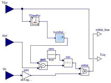
This model computes the mass transfer based on similarity laws between the convective sensible heat transfer coefficient and the mass transfer coefficient.
Using the Lewis number which is defined as the ratio between the heat and mass diffusion coefficients, one can obtain the ratio between convection heat transfer coefficient h in (W/(m^2*K)) and mass transfer coefficient hm in (m/s) as follows:
h ⁄ hm = ρ cp Le(1-n) ⁄ hm
where ρ is the mass density, cp is the specific heat capacity of the bulk medium and n is a coefficient from the boundary layer analysis, which is typically n=1/3. From this equation, we can compute the water vapor mass flow rate nA in (kg/s) as
nA = Gc ⁄ (cp Le(1-n)) (Xs - X∞),
where Gc is the sensible heat conductivity in (W/K) and Xs and X∞ are the water vapor mass per unit volume in the boundary layer and in the bulk of the medium. In this model, Xs is the saturation water vapor pressure corresponding to the temperature Tsur which is an input.
Extends from Buildings.BaseClasses.BaseIcon (Base icon).
| Type | Name | Default | Description |
|---|---|---|---|
| replaceable package Medium | Modelica.Media.Interfaces.Pa... | Fluid medium model | |
| Real | Le | 1 | Lewis number (around 1 for water vapor in air) |
| Real | n | 1/3 | Exponent in bondary layer ratio, delta/delta_t = Pr^n |
| Type | Name | Description |
|---|---|---|
| replaceable package Medium | Fluid medium model | |
| input RealInput | XInf | Water mass fraction of medium |
| input RealInput | TSur | Surface temperature [K] |
| output RealOutput | mWat_flow | Water flow rate [kg/s] |
| output RealOutput | TLiq | Temperature at which condensate drains from system [K] |
| input RealInput | Gc | Signal representing the convective (sensible) thermal conductance in [W/K] |
model MassExchange
  "Block to compute the latent heat transfer based on the Lewis number"
  extends Buildings.BaseClasses.BaseIcon;
  replaceable package Medium = Modelica.Media.Interfaces.PartialMedium
    "Fluid medium model";

  Modelica.Blocks.Interfaces.RealInput XInf "Water mass fraction of medium";
  Modelica.Blocks.Interfaces.RealInput TSur(final quantity="ThermodynamicTemperature",
                                            final unit = "K", displayUnit = "degC", min=0)
    "Surface temperature";
  Modelica.Blocks.Interfaces.RealOutput mWat_flow(final unit = "kg/s")
    "Water flow rate";
  Modelica.Blocks.Interfaces.RealOutput TLiq(final quantity="ThermodynamicTemperature",
                                             final unit = "K", displayUnit = "degC", min=0)
    "Temperature at which condensate drains from system";
  Modelica.Blocks.Interfaces.RealInput Gc
    "Signal representing the convective (sensible) thermal conductance in [W/K]";
  parameter Real Le = 1 "Lewis number (around 1 for water vapor in air)";
  parameter Real n = 1/3
    "Exponent in bondary layer ratio, delta/delta_t = Pr^n";
public
  Buildings.Utilities.Psychrometrics.X_pW humRatPre(use_p_in=false)
    "Model to convert water vapor pressure into humidity ratio";
  Buildings.Utilities.Psychrometrics.pW_TDewPoi TDewPoi
    "Model to compute the water vapor pressure at the dew point";
  Modelica.Blocks.Math.Gain gain(k=1/cpLe_default)
    "Constant to convert from heat transfer to mass transfer";
  Modelica.Blocks.Math.Product mWat "Water flow rate";
  Modelica.Blocks.Math.Min min;
  Modelica.Blocks.Sources.Constant zero(k=0) "Constant for zero";
  Modelica.Blocks.Math.Add delX(k2=-1, k1=1) "Humidity difference";
protected
 parameter Medium.ThermodynamicState sta_default = Medium.setState_phX(h=Medium.h_default,
       p=Medium.p_default, X=Medium.X_default);
 parameter Modelica.SIunits.SpecificHeatCapacity cp_default=Medium.specificHeatCapacityCp(sta_default)
    "Density, used to compute fluid volume";
 parameter Real cpLe_default(unit="J/(kg.K)") = cp_default * Le^(1-n);
equation
  connect(TSur, TDewPoi.T);
  connect(TDewPoi.p_w, humRatPre.p_w);
  connect(TSur, TLiq);
  connect(Gc, gain.u);
  connect(gain.y, mWat.u2);
  connect(mWat.y, mWat_flow);
  connect(zero.y,min. u1);
  connect(delX.u2,XInf);
  connect(humRatPre.X_w, delX.u1);
  connect(delX.y, min.u2);
  connect(min.y, mWat.u1);
end MassExchange;
 Buildings.Fluid.HeatExchangers.BaseClasses.PartialEffectiveness
Partial model to implement heat exchanger models.
Classes that extend this model need to implement heat and mass balance equations in a form like
  // transfered heat
  Q1_flow = eps * QMax_flow;
  // no heat loss to ambient
  0 = Q1_flow + Q2_flow;
  // no mass exchange
  mXi1_flow = zeros(Medium1.nXi);
  mXi2_flow = zeros(Medium2.nXi);
Thus, if medium 1 is heated in this device, then Q1_flow > 0
and QMax_flow > 0.
| Type | Name | Default | Description |
|---|---|---|---|
| replaceable package Medium1 | PartialMedium | Medium 1 in the component | |
| replaceable package Medium2 | PartialMedium | Medium 2 in the component | |
| Boolean | sensibleOnly1 | Set to true if sensible exchange only for medium 1 | |
| Boolean | sensibleOnly2 | Set to true if sensible exchange only for medium 2 | |
| Nominal condition | |||
| MassFlowRate | m1_flow_nominal | Nominal mass flow rate [kg/s] | |
| MassFlowRate | m2_flow_nominal | Nominal mass flow rate [kg/s] | |
| Pressure | dp1_nominal | Pressure [Pa] | |
| Pressure | dp2_nominal | Pressure [Pa] | |
| Initialization | |||
| MassFlowRate | m1_flow.start | 0 | Mass flow rate from port_a1 to port_b1 (m1_flow > 0 is design flow direction) [kg/s] |
| Pressure | dp1.start | 0 | Pressure difference between port_a1 and port_b1 [Pa] |
| MassFlowRate | m2_flow.start | 0 | Mass flow rate from port_a2 to port_b2 (m2_flow > 0 is design flow direction) [kg/s] |
| Pressure | dp2.start | 0 | Pressure difference between port_a2 and port_b2 [Pa] |
| Assumptions | |||
| Boolean | allowFlowReversal1 | system.allowFlowReversal | = true to allow flow reversal in medium 1, false restricts to design direction (port_a -> port_b) |
| Boolean | allowFlowReversal2 | system.allowFlowReversal | = true to allow flow reversal in medium 2, false restricts to design direction (port_a -> port_b) |
| Advanced | |||
| Initialization | |||
| SpecificEnthalpy | h_outflow_a1_start | Medium1.h_default | Start value for enthalpy flowing out of port a1 [J/kg] |
| SpecificEnthalpy | h_outflow_b1_start | Medium1.h_default | Start value for enthalpy flowing out of port b1 [J/kg] |
| SpecificEnthalpy | h_outflow_a2_start | Medium2.h_default | Start value for enthalpy flowing out of port a2 [J/kg] |
| SpecificEnthalpy | h_outflow_b2_start | Medium2.h_default | Start value for enthalpy flowing out of port b2 [J/kg] |
| MassFlowRate | m1_flow_small | 1E-4*abs(m1_flow_nominal) | Small mass flow rate for regularization of zero flow [kg/s] |
| MassFlowRate | m2_flow_small | 1E-4*abs(m2_flow_nominal) | Small mass flow rate for regularization of zero flow [kg/s] |
| Boolean | homotopyInitialization | true | = true, use homotopy method |
| Diagnostics | |||
| Boolean | show_T | false | = true, if actual temperature at port is computed |
| Flow resistance | |||
| Medium 1 | |||
| Boolean | from_dp1 | false | = true, use m_flow = f(dp) else dp = f(m_flow) |
| Boolean | linearizeFlowResistance1 | false | = true, use linear relation between m_flow and dp for any flow rate |
| Real | deltaM1 | 0.1 | Fraction of nominal flow rate where flow transitions to laminar |
| Medium 2 | |||
| Boolean | from_dp2 | false | = true, use m_flow = f(dp) else dp = f(m_flow) |
| Boolean | linearizeFlowResistance2 | false | = true, use linear relation between m_flow and dp for any flow rate |
| Real | deltaM2 | 0.1 | Fraction of nominal flow rate where flow transitions to laminar |
| Type | Name | Description |
|---|---|---|
| FluidPort_a | port_a1 | Fluid connector a1 (positive design flow direction is from port_a1 to port_b1) |
| FluidPort_b | port_b1 | Fluid connector b1 (positive design flow direction is from port_a1 to port_b1) |
| FluidPort_a | port_a2 | Fluid connector a2 (positive design flow direction is from port_a2 to port_b2) |
| FluidPort_b | port_b2 | Fluid connector b2 (positive design flow direction is from port_a2 to port_b2) |
partial model PartialEffectiveness
  "Partial model to implement heat exchangers based on effectiveness model"
  extends Fluid.Interfaces.StaticFourPortHeatMassExchanger(show_T=false);

  Modelica.SIunits.Temperature T_in1 "Inlet temperature medium 1";
  Modelica.SIunits.Temperature T_in2 "Inlet temperature medium 2";
  Modelica.SIunits.ThermalConductance C1_flow
    "Heat capacity flow rate medium 1";
  Modelica.SIunits.ThermalConductance C2_flow
    "Heat capacity flow rate medium 2";
  Modelica.SIunits.ThermalConductance CMin_flow(min=0)
    "Minimum heat capacity flow rate";
  Modelica.SIunits.HeatFlowRate QMax_flow
    "Maximum heat flow rate into medium 1";
protected
  parameter Real delta=1E-3 "Parameter used for smoothing";

  parameter Modelica.SIunits.SpecificHeatCapacity cp1_default(fixed=false)
    "Specific heat capacity of medium 1 at default medium state";
  parameter Modelica.SIunits.SpecificHeatCapacity cp2_default(fixed=false)
    "Specific heat capacity of medium 2 at default medium state";
  parameter Modelica.SIunits.ThermalConductance CMin_flow_small(fixed=false)
    "Small value for smoothing of minimum heat capacity flow rate";
  Real fra_a1(min=0, max=1)
    "Fraction of incoming state taken from port a2 (used to avoid excessive calls to regStep)";
  Real fra_b1(min=0, max=1)
    "Fraction of incoming state taken from port b2 (used to avoid excessive calls to regStep)";
  Real fra_a2(min=0, max=1)
    "Fraction of incoming state taken from port a2 (used to avoid excessive calls to regStep)";
  Real fra_b2(min=0, max=1)
    "Fraction of incoming state taken from port b2 (used to avoid excessive calls to regStep)";
initial equation
  cp1_default = Medium1.specificHeatCapacityCp(Medium1.setState_pTX(
    Medium1.p_default,
    Medium1.T_default,
    Medium1.X_default));
  cp2_default = Medium2.specificHeatCapacityCp(Medium2.setState_pTX(
    Medium2.p_default,
    Medium2.T_default,
    Medium2.X_default));
  CMin_flow_small = min(m1_flow_small*cp1_default, m2_flow_small*cp2_default);
equation
  if allowFlowReversal2 then
    fra_a2 = Modelica.Fluid.Utilities.regStep(
      m2_flow,
      1,
      0,
      m2_flow_small);
    fra_b2 = 1-fra_a2;
  else
    fra_a2 = 1;
    fra_b2 = 0;
  end if;
  if allowFlowReversal1 then
    fra_a1 = Modelica.Fluid.Utilities.regStep(
      m1_flow,
      1,
      0,
      m1_flow_small);
    fra_b1 = 1-fra_a1;
  else
    fra_a1 = 1;
    fra_b1 = 0;
  end if;

  /////////////////////////////////////////////////////////
  // Definitions for heat transfer effectiveness model
  T_in1 = if allowFlowReversal1 then
    fra_a1 * Medium1.temperature(state_a1_inflow) + fra_b1 * Medium1.temperature(state_b1_inflow) else
    Medium1.temperature(state_a1_inflow);
  T_in2 = if allowFlowReversal2 then
    fra_a2 * Medium2.temperature(state_a2_inflow) + fra_b2 * Medium2.temperature(state_b2_inflow) else
    Medium2.temperature(state_a2_inflow);

  C1_flow = abs(m1_flow)*
    ( if allowFlowReversal1 then
           fra_a1 * Medium1.specificHeatCapacityCp(state_a1_inflow) +
           fra_b1 * Medium1.specificHeatCapacityCp(state_b1_inflow) else
        Medium1.specificHeatCapacityCp(state_a1_inflow));
  C2_flow = abs(m2_flow)*
    ( if allowFlowReversal2 then
           fra_a2 * Medium2.specificHeatCapacityCp(state_a2_inflow) +
           fra_b2 * Medium2.specificHeatCapacityCp(state_b2_inflow) else
        Medium2.specificHeatCapacityCp(state_a2_inflow));
  CMin_flow = min(C1_flow, C2_flow);

  // QMax_flow is maximum heat transfer into medium 1
  QMax_flow = CMin_flow*(T_in2 - T_in1);

end PartialEffectiveness;
 Buildings.Fluid.HeatExchangers.BaseClasses.PartialHexElement
Element of a heat exchanger with dynamics of the fluids and the solid. The hA value for both fluids is an input. The driving force for the heat transfer is the temperature difference between the fluid volumes and the solid.
The heat capacity C of the metal is assigned as follows. Suppose the metal temperature is governed by
C dT ⁄ dt = (hA)1 (T1 - T) + (hA)2 (T2 - T)
where hA are the convective heat transfer coefficients times heat transfer area that also take into account heat conduction in the heat exchanger fins and T1 and T2 are the medium temperatures. Assuming (hA)1=(hA)2, this equation can be rewritten as
C dT ⁄ dt = 2 (UA)0 ( (T1 - T) + (T2 - T) )
where (UA)0 is the UA value at nominal conditions. Hence we set the heat capacity of the metal to
C = 2 (UA)0 τm
where τm is the time constant that the metal of the heat exchanger has if the metal is approximated by a lumped thermal mass.
Note: This model is introduced to allow the instances
Buildings.Fluid.HeatExchangers.BaseClasses.HexElementLatent
and
Buildings.Fluid.HeatExchangers.BaseClasses.HexElementSensible
to redeclare the volume as final, thereby avoiding
that a GUI displays the volume as a replaceable component.
| Type | Name | Default | Description |
|---|---|---|---|
| replaceable package Medium1 | PartialMedium | Medium 1 in the component | |
| replaceable package Medium2 | PartialMedium | Medium 2 in the component | |
| MixingVolume | vol2 | redeclare Buildings.Fluid.Mi... | Volume for fluid 2 |
| HeatCapacity | C | 2*UA_nominal*tau_m | Heat capacity of metal (= cp*m) [J/K] |
| Nominal condition | |||
| MassFlowRate | m1_flow_nominal | Nominal mass flow rate [kg/s] | |
| MassFlowRate | m2_flow_nominal | Nominal mass flow rate [kg/s] | |
| Pressure | dp1_nominal | Pressure [Pa] | |
| Pressure | dp2_nominal | Pressure [Pa] | |
| ThermalConductance | UA_nominal | Thermal conductance at nominal flow, used to compute time constant [W/K] | |
| Time | tau_m | 60 | Time constant of metal at nominal UA value [s] |
| Initialization | |||
| MassFlowRate | m1_flow.start | 0 | Mass flow rate from port_a1 to port_b1 (m1_flow > 0 is design flow direction) [kg/s] |
| Pressure | dp1.start | 0 | Pressure difference between port_a1 and port_b1 [Pa] |
| MassFlowRate | m2_flow.start | 0 | Mass flow rate from port_a2 to port_b2 (m2_flow > 0 is design flow direction) [kg/s] |
| Pressure | dp2.start | 0 | Pressure difference between port_a2 and port_b2 [Pa] |
| Assumptions | |||
| Boolean | allowFlowReversal1 | system.allowFlowReversal | = true to allow flow reversal in medium 1, false restricts to design direction (port_a -> port_b) |
| Boolean | allowFlowReversal2 | system.allowFlowReversal | = true to allow flow reversal in medium 2, false restricts to design direction (port_a -> port_b) |
| Advanced | |||
| MassFlowRate | m1_flow_small | 1E-4*abs(m1_flow_nominal) | Small mass flow rate for regularization of zero flow [kg/s] |
| MassFlowRate | m2_flow_small | 1E-4*abs(m2_flow_nominal) | Small mass flow rate for regularization of zero flow [kg/s] |
| Boolean | homotopyInitialization | true | = true, use homotopy method |
| Diagnostics | |||
| Boolean | show_T | false | = true, if actual temperature at port is computed |
| Flow resistance | |||
| Medium 1 | |||
| Boolean | from_dp1 | false | = true, use m_flow = f(dp) else dp = f(m_flow) |
| Boolean | linearizeFlowResistance1 | false | = true, use linear relation between m_flow and dp for any flow rate |
| Real | deltaM1 | 0.1 | Fraction of nominal flow rate where flow transitions to laminar |
| Medium 2 | |||
| Boolean | from_dp2 | false | = true, use m_flow = f(dp) else dp = f(m_flow) |
| Boolean | linearizeFlowResistance2 | false | = true, use linear relation between m_flow and dp for any flow rate |
| Real | deltaM2 | 0.1 | Fraction of nominal flow rate where flow transitions to laminar |
| Dynamics | |||
| Nominal condition | |||
| Time | tau1 | 30 | Time constant at nominal flow [s] |
| Time | tau2 | 30 | Time constant at nominal flow [s] |
| Equations | |||
| Dynamics | energyDynamics | Modelica.Fluid.Types.Dynamic... | Formulation of energy balance |
| Dynamics | massDynamics | energyDynamics | Formulation of mass balance |
| Dynamics | energyDynamics1 | Modelica.Fluid.Types.Dynamic... | Default formulation of energy balances for volume 1 |
| Dynamics | energyDynamics2 | Modelica.Fluid.Types.Dynamic... | Default formulation of energy balances for volume 2 |
| Initialization | |||
| Medium 1 | |||
| AbsolutePressure | p1_start | Medium1.p_default | Start value of pressure [Pa] |
| Temperature | T1_start | Medium1.T_default | Start value of temperature [K] |
| MassFraction | X1_start[Medium1.nX] | Medium1.X_default | Start value of mass fractions m_i/m [kg/kg] |
| ExtraProperty | C1_start[Medium1.nC] | fill(0, Medium1.nC) | Start value of trace substances |
| ExtraProperty | C1_nominal[Medium1.nC] | fill(1E-2, Medium1.nC) | Nominal value of trace substances. (Set to typical order of magnitude.) |
| Medium 2 | |||
| AbsolutePressure | p2_start | Medium2.p_default | Start value of pressure [Pa] |
| Temperature | T2_start | Medium2.T_default | Start value of temperature [K] |
| MassFraction | X2_start[Medium2.nX] | Medium2.X_default | Start value of mass fractions m_i/m [kg/kg] |
| ExtraProperty | C2_start[Medium2.nC] | fill(0, Medium2.nC) | Start value of trace substances |
| ExtraProperty | C2_nominal[Medium2.nC] | fill(1E-2, Medium2.nC) | Nominal value of trace substances. (Set to typical order of magnitude.) |
| Type | Name | Description |
|---|---|---|
| FluidPort_a | port_a1 | Fluid connector a1 (positive design flow direction is from port_a1 to port_b1) |
| FluidPort_b | port_b1 | Fluid connector b1 (positive design flow direction is from port_a1 to port_b1) |
| FluidPort_a | port_a2 | Fluid connector a2 (positive design flow direction is from port_a2 to port_b2) |
| FluidPort_b | port_b2 | Fluid connector b2 (positive design flow direction is from port_a2 to port_b2) |
| input RealInput | Gc_1 | Signal representing the convective thermal conductance medium 1 in [W/K] |
| input RealInput | Gc_2 | Signal representing the convective thermal conductance medium 2 in [W/K] |
model PartialHexElement "Element of a heat exchanger 2"
  extends Buildings.Fluid.Interfaces.FourPortHeatMassExchanger(
   vol1(final energyDynamics=energyDynamics1,
        final massDynamics=energyDynamics1));

  parameter Modelica.SIunits.ThermalConductance UA_nominal
    "Thermal conductance at nominal flow, used to compute time constant";
  parameter Modelica.SIunits.Time tau_m(min=0) = 60
    "Time constant of metal at nominal UA value";
  parameter Modelica.SIunits.HeatCapacity C=2*UA_nominal*tau_m
    "Heat capacity of metal (= cp*m)";

  Modelica.Blocks.Interfaces.RealInput Gc_1
    "Signal representing the convective thermal conductance medium 1 in [W/K]";
  Modelica.Blocks.Interfaces.RealInput Gc_2
    "Signal representing the convective thermal conductance medium 2 in [W/K]";

  parameter Modelica.Fluid.Types.Dynamics energyDynamics1=
    Modelica.Fluid.Types.Dynamics.DynamicFreeInitial
    "Default formulation of energy balances for volume 1";
  parameter Modelica.Fluid.Types.Dynamics energyDynamics2=
    Modelica.Fluid.Types.Dynamics.DynamicFreeInitial
    "Default formulation of energy balances for volume 2";

  Modelica.Thermal.HeatTransfer.Components.HeatCapacitor mas(
    C=C,
    T(stateSelect=StateSelect.always)) "Mass of metal";
  Modelica.Thermal.HeatTransfer.Components.Convection con1(dT(min=-200))
    "Convection (and conduction) on fluid side 1";
  Modelica.Thermal.HeatTransfer.Components.Convection con2(dT(min=-200))
    "Convection (and conduction) on fluid side 2";
equation
  connect(Gc_1, con1.Gc);
  connect(Gc_2, con2.Gc);
  connect(con1.solid,mas. port);
  connect(con2.solid,mas. port);
  connect(con1.fluid, vol1.heatPort);
  connect(con2.fluid, vol2.heatPort);
end PartialHexElement;
 Buildings.Fluid.HeatExchangers.BaseClasses.PartialDuctManifold
Partial duct manifold for a heat exchanger.
This model defines the duct connection to a heat exchanger. It is extended by other models that model the flow connection between the ports with and without flow friction.
Extends from PartialDuctPipeManifold (Partial heat exchanger duct and pipe manifold).
| Type | Name | Default | Description |
|---|---|---|---|
| replaceable package Medium | PartialMedium | Medium in the component | |
| Integer | nPipPar | Number of parallel pipes in each register | |
| Integer | nPipSeg | Number of pipe segments per register used for discretization | |
| Initialization | |||
| MassFlowRate | mStart_flow_a | Guess value for mass flow rate at port_a [kg/s] | |
| Assumptions | |||
| Boolean | allowFlowReversal | system.allowFlowReversal | = true to allow flow reversal, false restricts to design direction (port_a -> port_b) |
| Type | Name | Description |
|---|---|---|
| FluidPort_a | port_a | Fluid connector a for medium (positive design flow direction is from port_a to port_b) |
| FluidPort_b | port_b[nPipPar, nPipSeg] | Fluid connector b for medium (positive design flow direction is from port_a to port_b) |
partial model PartialDuctManifold
  "Partial manifold for heat exchanger duct connection"
  extends PartialDuctPipeManifold;
  parameter Integer nPipSeg(min=1)
    "Number of pipe segments per register used for discretization";

  Modelica.Fluid.Interfaces.FluidPort_b[nPipPar,nPipSeg] port_b(
        redeclare each package Medium = Medium,
        each m_flow(start=-mStart_flow_a/nPipSeg/nPipPar,
             max=if allowFlowReversal then +Modelica.Constants.inf else 0))
    "Fluid connector b for medium (positive design flow direction is from port_a to port_b)";
end PartialDuctManifold;
 Buildings.Fluid.HeatExchangers.BaseClasses.PartialDuctPipeManifold
Partial heat exchanger manifold. This partial model defines ports and parameters that are used for air-side and water-side heat exchanger manifolds.
Extends from Buildings.BaseClasses.BaseIcon (Base icon).
| Type | Name | Default | Description |
|---|---|---|---|
| replaceable package Medium | Modelica.Media.Interfaces.Pa... | Medium in the component | |
| Integer | nPipPar | Number of parallel pipes in each register | |
| Initialization | |||
| MassFlowRate | mStart_flow_a | Guess value for mass flow rate at port_a [kg/s] | |
| Assumptions | |||
| Boolean | allowFlowReversal | system.allowFlowReversal | = true to allow flow reversal, false restricts to design direction (port_a -> port_b) |
| Type | Name | Description |
|---|---|---|
| replaceable package Medium | Medium in the component | |
| FluidPort_a | port_a | Fluid connector a for medium (positive design flow direction is from port_a to port_b) |
partial model PartialDuctPipeManifold
  "Partial heat exchanger duct and pipe manifold"
  extends Buildings.BaseClasses.BaseIcon;

  outer Modelica.Fluid.System system "System wide properties";

  replaceable package Medium =
      Modelica.Media.Interfaces.PartialMedium "Medium in the component";

  parameter Boolean allowFlowReversal = system.allowFlowReversal
    "= true to allow flow reversal, false restricts to design direction (port_a -> port_b)";

  parameter Integer nPipPar(min=1) "Number of parallel pipes in each register";

  parameter Modelica.SIunits.MassFlowRate mStart_flow_a
    "Guess value for mass flow rate at port_a";

  Modelica.Fluid.Interfaces.FluidPort_a port_a(
        redeclare package Medium = Medium,
        m_flow(start=mStart_flow_a, min=if allowFlowReversal then -Modelica.Constants.inf else 0))
    "Fluid connector a for medium (positive design flow direction is from port_a to port_b)";
end PartialDuctPipeManifold;
 Buildings.Fluid.HeatExchangers.BaseClasses.PartialPipeManifold
Partial pipe manifold for a heat exchanger.
This model defines the pipe connection to a heat exchanger. It is extended by other models that model the flow connection between the ports with and without flow friction.
Extends from PartialDuctPipeManifold (Partial heat exchanger duct and pipe manifold).
| Type | Name | Default | Description |
|---|---|---|---|
| replaceable package Medium | PartialMedium | Medium in the component | |
| Integer | nPipPar | Number of parallel pipes in each register | |
| Initialization | |||
| MassFlowRate | mStart_flow_a | Guess value for mass flow rate at port_a [kg/s] | |
| Assumptions | |||
| Boolean | allowFlowReversal | system.allowFlowReversal | = true to allow flow reversal, false restricts to design direction (port_a -> port_b) |
| Type | Name | Description |
|---|---|---|
| FluidPort_a | port_a | Fluid connector a for medium (positive design flow direction is from port_a to port_b) |
| FluidPort_b | port_b[nPipPar] | Fluid connector b for medium (positive design flow direction is from port_a to port_b) |
partial model PartialPipeManifold "Partial pipe manifold for a heat exchanger" extends PartialDuctPipeManifold;Modelica.Fluid.Interfaces.FluidPort_b[nPipPar] port_b( redeclare each package Medium = Medium, each m_flow(start=-mStart_flow_a/nPipPar, max=if allowFlowReversal then +Modelica.Constants.inf else 0)) "Fluid connector b for medium (positive design flow direction is from port_a to port_b)"; end PartialPipeManifold;
 Buildings.Fluid.HeatExchangers.BaseClasses.PipeManifoldFixedResistance
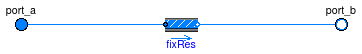
Pipe manifold with a fixed flow resistance.
This model causes the flow to be distributed equally into each flow path by using a fixed flow resistance for each flow path.
Extends from PartialPipeManifold (Partial pipe manifold for a heat exchanger).
| Type | Name | Default | Description |
|---|---|---|---|
| replaceable package Medium | PartialMedium | Medium in the component | |
| Integer | nPipPar | Number of parallel pipes in each register | |
| Boolean | use_dh | false | Set to true to specify hydraulic diameter |
| Length | dh | 0.025 | Hydraulic diameter for each pipe [m] |
| Real | ReC | 4000 | Reynolds number where transition to turbulent starts |
| Real | deltaM | 0.3 | Fraction of nominal mass flow rate where transition to turbulent occurs |
| Initialization | |||
| MassFlowRate | mStart_flow_a | Guess value for mass flow rate at port_a [kg/s] | |
| Nominal Condition | |||
| MassFlowRate | m_flow_nominal | Mass flow rate at port_a [kg/s] | |
| Pressure | dp_nominal | Pressure [Pa] | |
| Assumptions | |||
| Boolean | allowFlowReversal | system.allowFlowReversal | = true to allow flow reversal, false restricts to design direction (port_a -> port_b) |
| Advanced | |||
| Boolean | linearized | false | = true, use linear relation between m_flow and dp for any flow rate |
| Boolean | from_dp | false | = true, use m_flow = f(dp) else dp = f(m_flow) |
| Type | Name | Description |
|---|---|---|
| FluidPort_a | port_a | Fluid connector a for medium (positive design flow direction is from port_a to port_b) |
| FluidPort_b | port_b[nPipPar] | Fluid connector b for medium (positive design flow direction is from port_a to port_b) |
model PipeManifoldFixedResistance
  "Pipe manifold for a heat exchanger connection"
  extends PartialPipeManifold;

  parameter Modelica.SIunits.MassFlowRate m_flow_nominal
    "Mass flow rate at port_a";
  parameter Modelica.SIunits.Pressure dp_nominal(min=0) "Pressure";

  parameter Boolean use_dh = false "Set to true to specify hydraulic diameter";
  parameter Modelica.SIunits.Length dh=0.025 "Hydraulic diameter for each pipe";
  parameter Real ReC=4000
    "Reynolds number where transition to turbulent starts";
  parameter Boolean linearized = false
    "= true, use linear relation between m_flow and dp for any flow rate";
  parameter Real deltaM(min=0) = 0.3
    "Fraction of nominal mass flow rate where transition to turbulent occurs";
  parameter Boolean from_dp = false
    "= true, use m_flow = f(dp) else dp = f(m_flow)";

  Fluid.FixedResistances.FixedResistanceDpM[nPipPar] fixRes(
    redeclare each package Medium = Medium,
    each m_flow_nominal=m_flow_nominal/nPipPar,
    each m_flow(start=mStart_flow_a),
    each dp_nominal=dp_nominal,
    each dh=dh,
    each from_dp=from_dp,
    each deltaM=deltaM,
    each ReC=ReC,
    each use_dh=use_dh,
    each linearized=linearized) "Fixed resistance for each duct";
equation
  for i in 1:nPipPar loop
    connect(port_a, fixRes[i].port_a);
    connect(fixRes[i].port_b, port_b[i]);
  end for;
end PipeManifoldFixedResistance;
 Buildings.Fluid.HeatExchangers.BaseClasses.PipeManifoldNoResistance
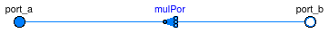
Pipe manifold without flow resistance.
This model connects the flows between the ports without modeling flow friction. The model is used in conjunction with a manifold which contains pressure drop elements and that is added to the other side of the heat exchanger registers.
Extends from PartialPipeManifold (Partial pipe manifold for a heat exchanger).
| Type | Name | Default | Description |
|---|---|---|---|
| replaceable package Medium | PartialMedium | Medium in the component | |
| Integer | nPipPar | Number of parallel pipes in each register | |
| Boolean | connectAllPressures | true | |
| Initialization | |||
| MassFlowRate | mStart_flow_a | Guess value for mass flow rate at port_a [kg/s] | |
| Assumptions | |||
| Boolean | allowFlowReversal | system.allowFlowReversal | = true to allow flow reversal, false restricts to design direction (port_a -> port_b) |
| Type | Name | Description |
|---|---|---|
| FluidPort_a | port_a | Fluid connector a for medium (positive design flow direction is from port_a to port_b) |
| FluidPort_b | port_b[nPipPar] | Fluid connector b for medium (positive design flow direction is from port_a to port_b) |
model PipeManifoldNoResistance "Manifold for heat exchanger register" extends PartialPipeManifold; parameter Boolean connectAllPressures=true;Modelica.Fluid.Fittings.MultiPort mulPor( redeclare package Medium = Medium, final nPorts_b=nPipPar); equationconnect(port_a, mulPor.port_a); connect(mulPor.ports_b, port_b); end PipeManifoldNoResistance;
 Buildings.Fluid.HeatExchangers.BaseClasses.RayleighNumber
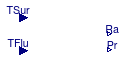
This model calculates the rayleigh number for a given fluid and characteristic length. It is calculated using Eq 9.25 in Incropera and DeWitt (1996). The equation is:
RaL = GrL Pr (g B (TS - TF) L3) /(ν*α)
where:
RaL is the Rayleigh number, GrL is the Grashof number, Pr
is the Prandtl number, g is gravity, B is the isobaric expansion coefficient,
TS is the temperature of the surface, TF is the temperature of the
fluid, L is the characteristic length, ν is the kinematic viscosity and α
is the thermal diffusivity.
This model is currently only used in natural convection calculations for water. As a result, the calculations reference functions to identify properties of water instead of a medium model.
Fundamentals of Heat and Mass Transfer (Fourth Edition), Frank Incropera and David DeWitt, John Wiley and Sons, 1996
Extends from Modelica.Blocks.Interfaces.BlockIcon (Basic graphical layout of input/output block).
| Type | Name | Default | Description |
|---|---|---|---|
| replaceable package Medium | Modelica.Media.Interfaces.Pa... | Fluid medium model | |
| Diameter | ChaLen | Characteristic length [m] | |
| Type | Name | Description |
|---|---|---|
| replaceable package Medium | Fluid medium model | |
| input RealInput | TSur | Surface temperature of the HX [K] |
| output RealOutput | Ra | Rayleigh number |
| output RealOutput | Pr | Prandlt number |
| input RealInput | TFlu | Temperature of the surrounding fluid [K] |
model RayleighNumber
  "Calculates the Rayleigh number for a given fluid and characteristic length"
  extends Modelica.Blocks.Interfaces.BlockIcon;
   replaceable package Medium = Modelica.Media.Interfaces.PartialMedium
    "Fluid medium model";
  parameter Modelica.SIunits.Diameter ChaLen "Characteristic length";
  Real Gr "Grashof number";
  Real B(unit="1/K") "isobaricExpansionCoefficient";
  Real nu(unit = "m2/s") "Kinematic viscosity of the medium";
  Modelica.SIunits.DynamicViscosity mu "Dynamic viscosity of the medium";
  Modelica.SIunits.Density rho "Density of the medium";

   Modelica.Blocks.Interfaces.RealInput TSur(unit = "K")
    "Surface temperature of the HX";

   Modelica.Blocks.Interfaces.RealOutput Ra "Rayleigh number";

   Modelica.Blocks.Interfaces.RealOutput Pr "Prandlt number";
   Modelica.Blocks.Interfaces.RealInput TFlu(unit="K")
    "Temperature of the surrounding fluid";
equation
    mu = Buildings.Fluid.HeatExchangers.BaseClasses.dynamicViscosityWater(
        T=  0.5 * (TSur+TFlu));
    rho = Medium.density(
        Medium.setState_pTX(
        p=  Medium.p_default,
        T=  0.5*(TSur+TFlu),
        X=  Medium.X_default));
    Pr = Buildings.Fluid.HeatExchangers.BaseClasses.prandtlNumberWater(
          T=  0.5*(TSur+TFlu));

    B = Buildings.Fluid.HeatExchangers.BaseClasses.isobaricExpansionCoefficientWater(
          T=  0.5*(TSur+TFlu));
    nu = mu/rho;

    Gr = Modelica.Constants.g_n * B * (TSur - TFlu)*ChaLen^3/nu^2;
    Ra = Gr*Pr;

end RayleighNumber;
This function computes iteratively the apparatus dew point temperature for a cooling coil. The apparatus dew point temperature is defined as in the HVAC2 Toolkit (Brandemuehl et al. 1993), namely as the intersection of the line between coil air inlet state (T,X) and outlet state, and the saturation line.
This function does its own iterations to find a solution because a solution may not exist or not be unique because the saturation line is convex. Therefore, this function searches for the solution starting at the air inlet temperature and progressively reduces the guess value for the apparatus dew point temperature. When a temperature below the apparatus dew point temperature has been found, it is rejected, and the search continues with a smaller step until the step size is smaller than a prescribed value. This ensures that the solution corresponding to the higher temperature is found. If no solution can be found, the function stops the simulation.
Brandemuehl, Michael, Shauna Gabel and Inger Andresen. HVAC2 Toolkit, A toolkit for secondary HVAC system energy calculations. ASHRAE, Atlanta. 1993.
| Type | Name | Default | Description |
|---|---|---|---|
| Temperature | TAir_in | Air inlet temperature at design condition [K] | |
| Temperature | TAir_out | Air inlet temperature at design condition [K] | |
| MassFraction | XW_in | Water vapor concentration at coil inlet at design condition [1] | |
| MassFraction | XW_out | Water vapor concentration at coil outlet at design condition [1] |
| Type | Name | Description |
|---|---|---|
| Temperature | T_dp | Apparatus dew point temperature [K] |
| MassFraction | XW_dp | Water vapor concentration at apparatus dew point [1] |
| Real | m | Slope, used to compute apparatus dewpoint temperature [1/K] |
function appartusDewPoint
  "Computes the apparatus dewpoint temperature"
  import psy = Buildings.Utilities.Psychrometrics.Functions;

  input Modelica.SIunits.Temperature TAir_in
    "Air inlet temperature at design condition";
  input Modelica.SIunits.Temperature TAir_out
    "Air inlet temperature at design condition";

  input Modelica.SIunits.MassFraction XW_in
    "Water vapor concentration at coil inlet at design condition";
  input Modelica.SIunits.MassFraction XW_out
    "Water vapor concentration at coil outlet at design condition";
  output Modelica.SIunits.Temperature T_dp "Apparatus dew point temperature";
  output Modelica.SIunits.MassFraction XW_dp
    "Water vapor concentration at apparatus dew point";
  output Real m(unit="1/K")
    "Slope, used to compute apparatus dewpoint temperature";

protected
  Modelica.SIunits.Temperature T "Iteration variable for temperature";
  Modelica.SIunits.Temperature dT
    "Temperature increment used in initial search";
  constant Modelica.SIunits.Temperature dTMin = 1E-10
    "Minimum temperature increment used during search";

  Integer i "Number of iterations";
  constant Integer iMax = 1000 "Maximum number of iterations";

  Real m_nominal(unit="1/K")
    "Slope based on nominal conditions, used to compute apparatus dewpoint temperature";
  Boolean converged "Flag to control iteration";

algorithm
  // Slope at design condition
  m_nominal :=(XW_in - XW_out)/(TAir_in - TAir_out);
  // Start value for iteration
  T_dp :=TAir_in;
  dT :=1;
  converged :=false;
  i :=0;
  while not converged loop
    i :=i + 1;
    assert(i < iMax, "Maximum number of iterations exceeded in computing\n"
      + "apparatus dew point for coil at nominal conditions"
      + "\n  Best known approximation is T_dp = " + String(T_dp)
      + "\n  Search step is dT = " + String(dT));

    T :=T_dp - dT;
    // New trial value
    XW_dp :=psy.X_pW(psy.pW_TDewPoi(T));
    m :=(XW_in - XW_dp)/(TAir_in - T);
    if (m < m_nominal) then // T is above dew point
       T_dp :=T; // Accept T as new approximation to solution
    else // T is below dew point.
       if (dT < dTMin) then // achieved required accuracy
         T_dp :=T;
         converged :=true;
       else  // need to shorten step. Reject last iterate T
         dT:=dT/10;
         T :=T_dp; // Resets T to last known value above dew point
       end if;
    end if;
  end while;
end appartusDewPoint;
This function is used to identify the dynamic viscosity of water at a given temperature. The function used is a fourth order polynomial fit to data from Incropera and Dewitt (1996).
Fundamentals of Heat and Mass Transfer (Fourth Edition), Frank Incropera and David P. Dewitt, John Wiley & Sons, 1996
| Type | Name | Default | Description |
|---|---|---|---|
| Temperature | T | Thermodynamic state record [K] |
| Type | Name | Description |
|---|---|---|
| DynamicViscosity | mu | Dynamic viscosity [Pa.s] |
function dynamicViscosityWater
  "Returns the dynamic viscosity for water"
    input Modelica.SIunits.Temperature T "Thermodynamic state record";
    output Modelica.SIunits.DynamicViscosity mu "Dynamic viscosity";
algorithm
        mu := ((2.86651*10^(-5))*T^4-0.039376307*T^3+20.32805026*T^2-
        4680.303158*T+406389.0375)*10^(-6);
        //Equation is a fourth order polynomial fit to data from Fundamentals of
        //Heat and Mass Transfer (Fourth Edition), Frank Incropera & David DeWitt,
        //John Wiley & Sons, 1996

end dynamicViscosityWater;
This function computes the heat exchanger effectiveness, the Number of Transfer Units, and the capacity flow ratio for given capacity flow rates.
The implementation allows for zero flow rate.
As CMin_flow crosses delta*CMin_flow_nominal from above,
the Number of Transfer Units and the heat exchanger effectiveness go to zero.
| Type | Name | Default | Description |
|---|---|---|---|
| ThermalConductance | UA | UA value [W/K] | |
| ThermalConductance | C1_flow | Enthalpy flow rate medium 1 [W/K] | |
| ThermalConductance | C2_flow | Enthalpy flow rate medium 2 [W/K] | |
| HeatExchangerFlowRegime | flowRegime | Heat exchanger flow regime | |
| ThermalConductance | CMin_flow_nominal | Minimum enthalpy flow rate at nominal condition [W/K] | |
| ThermalConductance | CMax_flow_nominal | Maximum enthalpy flow rate at nominal condition [W/K] | |
| Real | delta | 1E-3 | Small value used for smoothing |
| Type | Name | Description |
|---|---|---|
| Real | eps | Heat exchanger effectiveness |
| Real | NTU | Number of transfer units |
| Real | Z | Ratio of capacity flow rate (CMin/CMax) |
function epsilon_C
  "Computes heat exchanger effectiveness for given capacity flow rates and heat exchanger flow regime"
  import f = Buildings.Fluid.Types.HeatExchangerFlowRegime;
  input Modelica.SIunits.ThermalConductance UA "UA value";
  input Modelica.SIunits.ThermalConductance C1_flow
    "Enthalpy flow rate medium 1";
  input Modelica.SIunits.ThermalConductance C2_flow
    "Enthalpy flow rate medium 2";
  input Buildings.Fluid.Types.HeatExchangerFlowRegime flowRegime
    "Heat exchanger flow regime";
  input Modelica.SIunits.ThermalConductance CMin_flow_nominal
    "Minimum enthalpy flow rate at nominal condition";
  input Modelica.SIunits.ThermalConductance CMax_flow_nominal
    "Maximum enthalpy flow rate at nominal condition";
  input Real delta = 1E-3 "Small value used for smoothing";
  output Real eps(min=0, max=1) "Heat exchanger effectiveness";
  output Real NTU "Number of transfer units";
  output Real Z(min=0, max=1) "Ratio of capacity flow rate (CMin/CMax)";
protected
  Modelica.SIunits.ThermalConductance deltaCMin
    "Small number for capacity flow rate";
  Modelica.SIunits.ThermalConductance deltaCMax
    "Small number for capacity flow rate";
  Modelica.SIunits.ThermalConductance CMin_flow "Minimum capacity flow rate";
  Modelica.SIunits.ThermalConductance CMax_flow "Maximum capacity flow rate";
  Modelica.SIunits.ThermalConductance CMinNZ_flow
    "Minimum capacity flow rate, bounded away from zero";
  Modelica.SIunits.ThermalConductance CMaxNZ_flow
    "Maximum capacity flow rate, bounded away from zero";
  Real gai(min=0, max=1)
    "Gain used to force UA to zero for very small flow rates";
algorithm
  deltaCMin := delta*CMin_flow_nominal;
  deltaCMax := delta*CMax_flow_nominal;
  // effectiveness
  CMin_flow :=Buildings.Utilities.Math.Functions.smoothMin(
    C1_flow,
    C2_flow,
    deltaCMin/4);
  CMax_flow :=Buildings.Utilities.Math.Functions.smoothMax(
    C1_flow,
    C2_flow,
    deltaCMax/4);
  // CMin and CMax, constrained to be non-zero to compute eps-NTU-Z relationship
  CMinNZ_flow :=Buildings.Utilities.Math.Functions.smoothMax(
    CMin_flow,
    deltaCMin,
    deltaCMin/4);
  CMaxNZ_flow :=Buildings.Utilities.Math.Functions.smoothMax(
    CMax_flow,
    deltaCMax,
    deltaCMax/4);
  Z :=CMin_flow/CMaxNZ_flow;
  // Gain that goes to zero as CMin_flow gets below deltaCMin
  // This is needed to allow zero flow
  gai := Buildings.Utilities.Math.Functions.spliceFunction(
                 pos=1, neg=0, x=CMin_flow-deltaCMin, deltax=deltaCMin/2);
  if ( gai == 0) then
    NTU := 0;
    eps := 1; // around zero flow, eps=Q/(CMin*dT) should be one
  else
    NTU :=gai*UA/CMinNZ_flow;
    eps := gai*Buildings.Fluid.HeatExchangers.BaseClasses.epsilon_ntuZ(NTU=NTU, Z=Z, flowRegime=flowRegime);
  end if;

end epsilon_C;
| Type | Name | Default | Description |
|---|---|---|---|
| Real | NTU | Number of transfer units | |
| Real | Z | Ratio of capacity flow rate (CMin/CMax) | |
| HeatExchangerFlowRegime | flowRegime | Heat exchanger flow regime |
| Type | Name | Description |
|---|---|---|
| Real | eps | Heat exchanger effectiveness |
function epsilon_ntuZ
  "Computes heat exchanger effectiveness for given number of transfer units and heat exchanger flow regime"
  import f = Buildings.Fluid.Types.HeatExchangerFlowRegime;
  input Real NTU "Number of transfer units";
  input Real Z(min=0, max=1) "Ratio of capacity flow rate (CMin/CMax)";
  input Buildings.Fluid.Types.HeatExchangerFlowRegime flowRegime
    "Heat exchanger flow regime";
  output Real eps(min=0, max=1) "Heat exchanger effectiveness";
protected
  Real a "Auxiliary variable";
algorithm
  if (flowRegime == f.ParallelFlow) then // parallel flow
    a := 0;
    eps := (1 - Modelica.Math.exp(-NTU*(1 + Z)))/(1 + Z);
  elseif (flowRegime == f.CounterFlow) then// counter flow
   // a is constraining Z since eps is not defined for Z=1.
    a := smooth(1, if Z < 0.97 then Z else
      Buildings.Utilities.Math.Functions.smoothMin(
      x1=Z,
      x2=0.98,
      deltaX=0.01));
    eps := (1 - Modelica.Math.exp(-NTU*(1 - a)))/(1 - a*Modelica.Math.exp(-NTU*(
      1 - a)));
  elseif (flowRegime == f.CrossFlowUnmixed) then
   a := NTU^(-0.22);
    eps := 1 - Modelica.Math.exp( ( Modelica.Math.exp( - NTU * Z * a)  - 1)  / (Z * a));
  elseif (flowRegime == f.CrossFlowCMinUnmixedCMaxMixed) then
    // cross flow, (single pass), CMax mixed, CMin unmixed. (Coil with one row.)
    a := 0;
    eps := (1 - Modelica.Math.exp(-Z*(1 - Modelica.Math.exp(-NTU))))/Z;
  elseif (flowRegime == f.CrossFlowCMinMixedCMaxUnmixed) then
    // cross flow, (single pass), CMin mixed, CMax unmixed.
    a := 0;
    eps := 1 - Modelica.Math.exp(-(1 - Modelica.Math.exp(-Z*NTU))/Z);
  else
    a := 0;
    eps := 0;
    assert(f.ParallelFlow <= flowRegime and
           flowRegime <= f.CrossFlowCMinUnmixedCMaxMixed,
           "Flow regime is not implemented.");
  end if;
end epsilon_ntuZ;
This function is used to identify the isobaric expansion coefficient of water at a given temperature. The function used is a fourth order polynomial fit to data from Incropera and Dewitt (1996).
Fundamentals of Heat and Mass Transfer (Fourth Edition), Frank Incropera and David P. Dewitt, John Wiley & Sons, 1996
| Type | Name | Default | Description |
|---|---|---|---|
| Temperature | T | Thermodynamic state record [K] |
| Type | Name | Description |
|---|---|---|
| Real | beta | Dynamic viscosity [1/K] |
function isobaricExpansionCoefficientWater
  "Returns the isobaric expansion coefficient for water"
    input Modelica.SIunits.Temperature T "Thermodynamic state record";
    output Real beta( unit="1/K") "Dynamic viscosity";
algorithm
        beta := (-8.53296*10^(-6)*T^4+0.011562287*T^3-5.88800657*T^2+
        1341.798661*T-115406.5225)*10^(-6);
        //Equation is a fourth order polynomial fit to data from Fundamentals of
        //Heat and Mass Transfer (Fourth Edition), Frank Incropera & David DeWitt,
        //John Wiley & Sons, 1996

end isobaricExpansionCoefficientWater;
This function computes the number of transfer units for a given heat exchanger effectiveness, capacity flow ratio and heat exchanger flow regime.
Note that for the flow regime CrossFlowUnmixed, computing the
function requires the numerical solution of an equation in one variable.
This is handled internally and not exposed to the global solver.
| Type | Name | Default | Description |
|---|---|---|---|
| Real | eps | Heat exchanger effectiveness | |
| Real | Z | Ratio of capacity flow rate (CMin/CMax) | |
| HeatExchangerFlowRegime | flowRegime | Heat exchanger flow regime |
| Type | Name | Description |
|---|---|---|
| Real | NTU | Number of transfer units |
function ntu_epsilonZ
  "Computes number of transfer units for given heat exchanger effectiveness and heat exchanger flow regime"
  import f = Buildings.Fluid.Types.HeatExchangerFlowRegime;
  input Real eps(min=0, max=0.999) "Heat exchanger effectiveness";
  input Real Z(min=0, max=1) "Ratio of capacity flow rate (CMin/CMax)";
  input Buildings.Fluid.Types.HeatExchangerFlowRegime flowRegime
    "Heat exchanger flow regime";
  output Real NTU "Number of transfer units";

protected
  Real a "Auxiliary variable";
algorithm
  if (flowRegime == f.ParallelFlow) then // parallel flow
    a := Z+1;
    assert(eps < 1/a,
      "Invalid input data. eps > 1/(1+Z) is physically not possible for parallel flow.
  Received eps = " + String(eps) + "
             Z = " + String(Z) + "
       1/(Z+1) = " + String(1/a));
    NTU := -(Modelica.Math.log(1-eps*a))/(a);
  elseif (flowRegime == f.CounterFlow) then// counter flow
   // a is constraining Z since eps is not defined for Z=1.
    a := smooth(1, if Z < 0.97 then Z else
      Buildings.Utilities.Math.Functions.smoothMin(
      x1=Z,
      x2=0.98,
      deltaX=0.01));
    NTU := Modelica.Math.log((1-eps)/(1-eps*a)) / (a-1);

  elseif (flowRegime == f.CrossFlowUnmixed) then
    a := 0;
    // The function Internal.solve evaluates epsilon_ntuZ at NTU=x_min-1e-10 and NTU=x_max+1e-10
    // when it solves iteratively epsilon_ntuZ for ntu
    // Therefore, we set x_min=1.5*1e-10 to prevent computing NTU^(-0.22)=(-1e-10)^(-0.22).
    NTU := Internal.solve(y_zero=eps, x_min=1.5*1e-10, x_max=1E6, pressure=Z);
  elseif (flowRegime == f.CrossFlowCMinUnmixedCMaxMixed) then
    // cross flow, (single pass), CMax mixed, CMin unmixed. (Coil with one row.)
   a := smooth(1, if Z > 0.03 then Z else
      Buildings.Utilities.Math.Functions.smoothMin(
      x1=0.02,
      x2=Z,
      deltaX=0.01));
    NTU := -Modelica.Math.log(1+(Modelica.Math.log(1-eps*a)/a));
  elseif (flowRegime == f.CrossFlowCMinMixedCMaxUnmixed) then
    // cross flow, (single pass), CMin mixed, CMax unmixed.
   a := smooth(1, if Z > 0.03 then Z else
      Buildings.Utilities.Math.Functions.smoothMin(
      x1=0.02,
      x2=Z,
      deltaX=0.01));
    NTU := -Modelica.Math.log(1+Z*Modelica.Math.log(1-eps))/Z;
  else
    a := 0;
    NTU := 0;
    assert(0 < flowRegime and flowRegime < 6, "Flow regime is not implemented.");
  end if;

end ntu_epsilonZ;
This function computes the log mean temperature difference of a heat exchanger.
Note that the implementation requires the temperature differences to be non-zero.
| Type | Name | Default | Description |
|---|---|---|---|
| Temperature | T_a1 | Temperature at port a1 [K] | |
| Temperature | T_b1 | Temperature at port b1 [K] | |
| Temperature | T_a2 | Temperature at port a2 [K] | |
| Temperature | T_b2 | Temperature at port b2 [K] |
| Type | Name | Description |
|---|---|---|
| TemperatureDifference | lmtd | Log-mean temperature difference [K] |
function lmtd "Log-mean temperature difference"
  input Modelica.SIunits.Temperature T_a1 "Temperature at port a1";
  input Modelica.SIunits.Temperature T_b1 "Temperature at port b1";
  input Modelica.SIunits.Temperature T_a2 "Temperature at port a2";
  input Modelica.SIunits.Temperature T_b2 "Temperature at port b2";
  output Modelica.SIunits.TemperatureDifference lmtd
    "Log-mean temperature difference";
protected
  Modelica.SIunits.TemperatureDifference dT1 "Temperature difference side 1";
  Modelica.SIunits.TemperatureDifference dT2 "Temperature difference side 2";
algorithm
  dT1 :=T_a1 - T_b2;
  dT2 :=T_b1 - T_a2;
  lmtd :=(dT2 - dT1)/Modelica.Math.log(dT2/dT1);
end lmtd;
This function is used to identify the Prandtl number of water at a given temperature. The function used is a fourth order polynomial fit to data from Incropera and Dewitt (1996).
Fundamentals of Heat and Mass Transfer (Fourth Edition), Frank Incropera and David P. Dewitt, John Wiley & Sons, 1996
| Type | Name | Default | Description |
|---|---|---|---|
| Temperature | T | Thermodynamic state record [K] |
| Type | Name | Description |
|---|---|---|
| Real | Pr | Prandtl number |
function prandtlNumberWater "Returns the Prandtl number for water"
    input Modelica.SIunits.Temperature T "Thermodynamic state record";
    output Real Pr "Prandtl number";
algorithm
        Pr := ((2.55713*10^(-7))*T^4-0.000350293*T^3+0.180259651*T^2-
        41.34104323*T+3571.372195);
        //Equation is a fourth order polynomial fit to data from Fundamentals
        //of Heat and Mass Transfer (Fourth Edition), Frank Incropera & David DeWitt,
        //John Wiley & Sons, 1996

end prandtlNumberWater;