Collection of validation models
Information
This package contains validation models for the classes in
Buildings.Controls.OBC.ASHRAE.G36_PR1.AHUs.SingleZone.VAV.SetPoints.
Note that most validation models contain simple input data
which may not be realistic, but for which the correct
output can be obtained through an analytic solution.
The examples plot various outputs, which have been verified against these
solutions. These model outputs are stored as reference data and
used for continuous validation whenever models in the library change.
Package Content
| Name |
Description |
 ExhaustDamper ExhaustDamper
|
Validate of the controller for actuated exhaust damper without fan |
| OutsideAirFlow
|
Validate the model of calculating minimum outdoor airflow setpoint |
| Supply_T
|
Validation model for outdoor minus room air temperature |
| Supply_u
|
Validation model for control input |
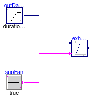
Validate of the controller for actuated exhaust damper without fan
Information
This example validates
Buildings.Controls.OBC.ASHRAE.G36_PR1.AHUs.SingleZone.VAV.SetPoints.ExhaustDamper.
Modelica definition
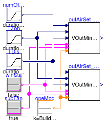
Validate the model of calculating minimum outdoor airflow setpoint
Information
This example validates
Buildings.Controls.OBC.ASHRAE.G36_PR1.AHUs.SingleZone.VAV.SetPoints.OutsideAirFlow.
Modelica definition
model OutsideAirFlow
Buildings.Controls.OBC.ASHRAE.G36_PR1.AHUs.SingleZone.VAV.SetPoints.OutsideAirFlow
outAirSet_SinZon(AFlo=40, have_occSen=true)
;
Buildings.Controls.OBC.CDL.Continuous.Sources.Ramp numOfOcc(
height=4,
duration=3600)
;
Buildings.Controls.OBC.ASHRAE.G36_PR1.AHUs.SingleZone.VAV.SetPoints.OutsideAirFlow
outAirSet_SinZon_noOccSen(AFlo=40, have_occSen=false)
;
protected
Buildings.Controls.OBC.CDL.Logical.Sources.Constant winSta(
k=false) ;
Buildings.Controls.OBC.CDL.Logical.Sources.Constant supFan(
k=true) ;
Buildings.Controls.OBC.CDL.Continuous.Sources.Ramp TZon(
height=6,
offset=273.15 + 17,
duration=3600) ;
Buildings.Controls.OBC.CDL.Continuous.Sources.Ramp TDis(
height=4,
duration=3600,
offset=273.15 + 18) ;
Buildings.Controls.OBC.CDL.Integers.Sources.Constant opeMod(
final k=Buildings.Controls.OBC.ASHRAE.G36_PR1.Types.OperationModes.occupied)
;
equation
connect(numOfOcc.y, outAirSet_SinZon.nOcc);
connect(winSta.y, outAirSet_SinZon.uWin);
connect(TZon.y, outAirSet_SinZon.TZon);
connect(outAirSet_SinZon.uOpeMod, opeMod.y);
connect(supFan.y, outAirSet_SinZon.uSupFan);
connect(TDis.y, outAirSet_SinZon.TDis);
connect(winSta.y, outAirSet_SinZon_noOccSen.uWin);
connect(TZon.y, outAirSet_SinZon_noOccSen.TZon);
connect(outAirSet_SinZon_noOccSen.uOpeMod, opeMod.y);
connect(supFan.y, outAirSet_SinZon_noOccSen.uSupFan);
connect(TDis.y, outAirSet_SinZon_noOccSen.TDis);
end OutsideAirFlow;
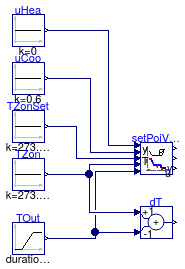
Validation model for outdoor minus room air temperature
Information
This example validates
Buildings.Controls.OBC.ASHRAE.G36_PR1.AHUs.SingleZone.VAV.SetPoints.Supply
for a change in temperature difference between zone air and outdoor air.
Hence, this model validates whether the adjustment of the fan speed for medium
cooling load is correct implemented.
Modelica definition
model Supply_T
Buildings.Controls.OBC.ASHRAE.G36_PR1.AHUs.SingleZone.VAV.SetPoints.Supply
setPoiVAV(
yHeaMax=0.7,
yMin=0.3,
TSupSetMax=303.15,
TSupSetMin=289.15,
yCooMax=0.9)
;
Buildings.Controls.OBC.CDL.Continuous.Sources.Constant uHea(k=0)
;
Buildings.Controls.OBC.CDL.Continuous.Sources.Constant uCoo(k=0.6)
;
Buildings.Controls.OBC.CDL.Continuous.Sources.Ramp TOut(
duration=1,
height=18,
offset=273.15 + 10) ;
Buildings.Controls.OBC.CDL.Continuous.Sources.Constant TZon(
k=273.15 + 22) ;
Buildings.Controls.OBC.CDL.Continuous.Add dT(k2=-1) ;
Buildings.Controls.OBC.CDL.Continuous.Sources.Constant TZonSet(
k=273.15 + 22) ;
equation
connect(uCoo.y, setPoiVAV.uCoo);
connect(TZon.y, setPoiVAV.TZon);
connect(TOut.y, setPoiVAV.TOut);
connect(uHea.y, setPoiVAV.uHea);
connect(dT.u1, TZon.y);
connect(dT.u2, TOut.y);
connect(TZonSet.y,setPoiVAV.TZonSet);
end Supply_T;
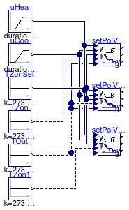
Validation model for control input
Information
This example validates
Buildings.Controls.OBC.ASHRAE.G36_PR1.AHUs.SingleZone.VAV.SetPoints.Supply
for different control signals.
Each controller is configured identical, but the input signal for TZon differs
in order to validate that the fan speed is increased correctly.
Modelica definition
model Supply_u
Buildings.Controls.OBC.ASHRAE.G36_PR1.AHUs.SingleZone.VAV.SetPoints.Supply
setPoiVAV(
yHeaMax=0.7,
yMin=0.3,
TSupSetMax=303.15,
TSupSetMin=289.15)
;
Buildings.Controls.OBC.ASHRAE.G36_PR1.AHUs.SingleZone.VAV.SetPoints.Supply
setPoiVAV1(
yHeaMax=0.7,
yMin=0.3,
TSupSetMax=303.15,
TSupSetMin=289.15)
;
Buildings.Controls.OBC.ASHRAE.G36_PR1.AHUs.SingleZone.VAV.SetPoints.Supply
setPoiVAV2(
yHeaMax=0.7,
yMin=0.3,
TSupSetMax=303.15,
TSupSetMin=289.15)
;
Buildings.Controls.OBC.CDL.Continuous.Sources.Constant TZon(k=273.15 + 28)
;
Buildings.Controls.OBC.CDL.Continuous.Sources.Constant TOut(k=273.15 + 22)
;
Buildings.Controls.OBC.CDL.Continuous.Sources.Ramp uHea(
duration=0.25,
height=-1,
offset=1) ;
Buildings.Controls.OBC.CDL.Continuous.Sources.Ramp uCoo(
duration=0.25,
startTime=0.75)
;
Buildings.Controls.OBC.CDL.Continuous.Sources.Constant TZonSet(k=273.15 + 23)
;
Buildings.Controls.OBC.CDL.Continuous.Sources.Constant TZon1(k=273.15 + 23)
;
equation
connect(TZon.y, setPoiVAV.TZon);
connect(TOut.y, setPoiVAV.TOut);
connect(uHea.y, setPoiVAV.uHea);
connect(uCoo.y, setPoiVAV.uCoo);
connect(TZonSet.y,setPoiVAV.TZonSet);
connect(TOut.y, setPoiVAV1.TOut);
connect(uHea.y, setPoiVAV1.uHea);
connect(uCoo.y, setPoiVAV1.uCoo);
connect(TZonSet.y,setPoiVAV1.TZonSet);
connect(TOut.y, setPoiVAV2.TOut);
connect(uHea.y, setPoiVAV2.uHea);
connect(uCoo.y, setPoiVAV2.uCoo);
connect(TZonSet.y,setPoiVAV2.TZonSet);
connect(TOut.y, setPoiVAV1.TZon);
connect(TZon1.y, setPoiVAV2.TZon);
end Supply_u;
 Buildings.Controls.OBC.ASHRAE.G36_PR1.AHUs.SingleZone.VAV.SetPoints.Validation.ExhaustDamper