Output setpoints for AHU control
Information
This package contains sequences generating setpoints for single zone VAV AHU control.
Package Content
| Name |
Description |
 ExhaustDamper ExhaustDamper
|
Control of actuated exhaust dampers without fans |
 OutsideAirFlow OutsideAirFlow
|
Output the minimum outdoor airflow rate setpoint for systems with a single zone |
 Supply Supply
|
Supply air set point for single zone VAV system |
 Validation Validation
|
Collection of validation models |
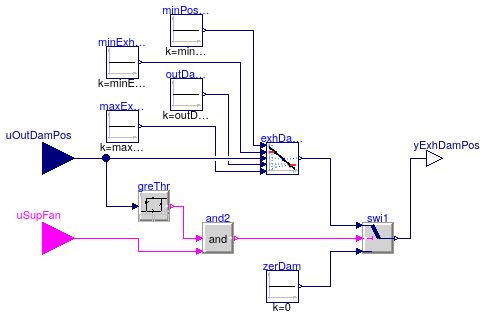
Control of actuated exhaust dampers without fans
Information
Control sequence for exhaust dampers without fans. It is implemented according
to ASHRAE Guidline 35 (G36), PART5.N.8.(for multi zone VAV AHU), PART5.P.6
and PART3.2B.3 (for single zone VAV AHU).
Single zone VAV AHU: Control of actuated exhaust dampers without fans (PART5.P.6)
- Exhaust damper position setpoints (PART3.2B.3)
minExhDamPos is the exhaust damper position that maintains a building
pressure of 12 Pa (0.05 inchWC) while the system is at minOutPosMin
(i.e., the economizer damper is positioned to provide minimum outdoor air while
the supply fan is at minimum speed).
-
maxExhDamPos is the exhaust damper position that maintains a building
pressure of 12 Pa (0.05 inchWC) while the economizer damper is fully
open and the fan speed is at cooling maximum.
-
The exhaust damper is enabled when the associated supply fan is proven on and
any outdoor air damper is open
uOutDamPos > 0 and disabled and closed
otherwise.
-
The exhaust damper position is reset linearly from
minExhDamPos to
maxExhDamPos as the commanded economizer damper position goes from
minOutPosMin to outDamPhyPosMax.
The control sequence is as follows:

Parameters
| Type | Name | Default | Description |
|---|
| Nominal parameters |
| Real | minExhDamPos | 0.1 | Exhaust damper position maintaining building static pressure at setpoint when the system is at minPosMin [1] |
| Real | maxExhDamPos | 0.9 | Exhaust damper position maintaining building static pressure at setpoint when outdoor air damper is fully open and fan speed is at cooling maximum [1] |
| Real | minOutPosMin | 0.4 | Outdoor air damper position when fan operating at minimum speed to supply minimum outdoor air flow [1] |
| Real | outDamPhyPosMax | 1 | Physical or at the comissioning fixed maximum position of the outdoor air damper [1] |
Connectors
| Type | Name | Description |
|---|
| input BooleanInput | uSupFan | Supply fan status |
| input RealInput | uOutDamPos | Outdoor air damper position [1] |
| output RealOutput | yExhDamPos | Exhaust damper position [1] |
Modelica definition
block ExhaustDamper
parameter Real minExhDamPos(
min=0,
max=1,
final unit="1") = 0.1
;
parameter Real maxExhDamPos(
min=0,
max=1,
final unit="1") = 0.9
;
parameter Real minOutPosMin(
min=0,
max=1,
final unit="1") = 0.4
;
parameter Real outDamPhyPosMax(
min=0,
max=1,
final unit="1")=1
;
Buildings.Controls.OBC.CDL.Interfaces.BooleanInput uSupFan ;
Buildings.Controls.OBC.CDL.Interfaces.RealInput uOutDamPos(
min=0,
max=1,
final unit="1")
;
Buildings.Controls.OBC.CDL.Interfaces.RealOutput yExhDamPos(
min=0,
max=1,
final unit="1") ;
Buildings.Controls.OBC.CDL.Continuous.Line exhDamPos
;
Buildings.Controls.OBC.CDL.Logical.Switch swi1
;
Buildings.Controls.OBC.CDL.Continuous.Hysteresis greThr(
final uLow=0.02,
final uHigh=0.05)
;
Buildings.Controls.OBC.CDL.Logical.And and2
;
protected
Buildings.Controls.OBC.CDL.Continuous.Sources.Constant zerDam(
final k=0)
;
Buildings.Controls.OBC.CDL.Continuous.Sources.Constant minExhDam(
final k=minExhDamPos)
;
Buildings.Controls.OBC.CDL.Continuous.Sources.Constant maxExhDam(
final k=maxExhDamPos)
;
Buildings.Controls.OBC.CDL.Continuous.Sources.Constant minPosAtMinSpd(
final k=minOutPosMin)
;
Buildings.Controls.OBC.CDL.Continuous.Sources.Constant outDamPhyPosMaxSig(
final k=outDamPhyPosMax)
;
equation
connect(outDamPhyPosMaxSig.y, exhDamPos.x2);
connect(maxExhDam.y, exhDamPos.f2);
connect(uOutDamPos, exhDamPos.u);
connect(zerDam.y, swi1.u3);
connect(and2.y, swi1.u2);
connect(minPosAtMinSpd.y, exhDamPos.x1);
connect(minExhDam.y, exhDamPos.f1);
connect(uOutDamPos, greThr.u);
connect(uSupFan, and2.u2);
connect(greThr.y, and2.u1);
connect(exhDamPos.y, swi1.u1);
connect(swi1.y, yExhDamPos);
end ExhaustDamper;
Output the minimum outdoor airflow rate setpoint for systems with a single zone
Information
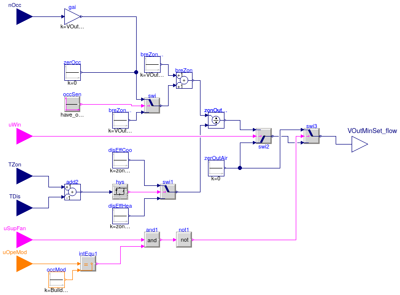
This atomic sequence sets the minimum outdoor airflow setpoint for compliance
with the ventilation rate procedure of ASHRAE 62.1-2013. The implementation
is according to ASHRAE Guidline 36 (G36), PART5.P.4.b, PART5.B.2.b, PART3.1-D.2.a.
Step 1: Minimum breathing zone outdoor airflow required breZon
- The area component of the breathing zone outdoor airflow:
breZonAre = AFlo*VOutPerAre_flow.
- The population component of the breathing zone outdoor airflow:
breZonPop = occCou*VOutPerPer_flow.
The number of occupant occCou could be retrieved
directly from occupancy sensor nOcc if the sensor exists
(have_occSen=true), or using the default occupant density
occDen to find it AFlo*occDen. The occupant
density can be found from Table 6.2.2.1 in ASHRAE Standard 62.1-2013.
Step 2: Zone air-distribution effectiveness zonDisEff
Table 6.2.2.2 in ASHRAE 62.1-2013 lists some typical values for setting the
effectiveness. Depending on difference between zone space temperature
TZon and supply air temperature TDis, Warm-air
effectiveness zonDisEffHea or Cool-air effectiveness
zonDisEffCoo should be applied.
Step 3: Minimum required zone outdoor airflow zonOutAirRate
For each zone in any mode other than occupied mode and for zones that have
window switches and the window is open, zonOutAirRate shall be
zero.
Otherwise, the required zone outdoor airflow zonOutAirRate
shall be calculated as follows:
If the zone is populated, or if there is no occupancy sensor:
- If discharge air temperature at the terminal unit is less than or equal to
zone space temperature:
zonOutAirRate = (breZonAre+breZonPop)/disEffCoo.
-
If discharge air temperature at the terminal unit is greater than zone space
temperature:
zonOutAirRate = (breZonAre+breZonPop)/disEffHea
If the zone has an occupancy sensor and is unpopulated:
- If discharge air temperature at the terminal unit is less than or equal to
zone space temperature:
zonOutAirRate = breZonAre/disEffCoo
- If discharge air temperature at the terminal unit is greater than zone
space temperature:
zonOutAirRate = breZonAre/disEffHea
For the single zone system, the required minimum outdoor airflow setpoint
VOutMinSet_flow equals to the zonOutAirRate.
Parameters
| Type | Name | Default | Description |
|---|
| Boolean | have_occSen | | Set to true if zones have occupancy sensor |
| Real | occDen | 0.05 | Default number of person in unit area [1/m2] |
| Real | zonDisEffHea | 0.8 | Zone air distribution effectiveness during heating [1] |
| Real | zonDisEffCoo | 1.0 | Zone air distribution effectiveness during cooling [1] |
| Nominal condition |
| Real | VOutPerAre_flow | 3e-4 | Outdoor air rate per unit area [m3/(s.m2)] |
| VolumeFlowRate | VOutPerPer_flow | 2.5e-3 | Outdoor air rate per person [m3/s] |
| Area | AFlo | | Floor area [m2] |
| Advanced |
| Real | uLow | -0.5 | If zone space temperature minus supply air temperature is less than uLow,
then it should use heating supply air distribution effectiveness [K] |
| Real | uHig | 0.5 | If zone space temperature minus supply air temperature is more than uHig,
then it should use cooling supply air distribution effectiveness [K] |
Connectors
| Type | Name | Description |
|---|
| input RealInput | nOcc | Number of occupants [1] |
| input RealInput | TZon | Measured zone air temperature [K] |
| input RealInput | TDis | Measured discharge air temperature [K] |
| input IntegerInput | uOpeMod | AHU operation mode status signal |
| input BooleanInput | uSupFan | Supply fan status, true if on, false if off |
| input BooleanInput | uWin | Window status, true if open, false if closed |
| output RealOutput | VOutMinSet_flow | Effective minimum outdoor airflow setpoint [m3/s] |
Modelica definition
block OutsideAirFlow
parameter Real VOutPerAre_flow(
final unit="m3/(s.m2)") = 3e-4
;
parameter Modelica.SIunits.VolumeFlowRate VOutPerPer_flow = 2.5e-3
;
parameter Modelica.SIunits.Area AFlo
;
parameter Boolean have_occSen
;
parameter Real occDen(
final unit="1/m2") = 0.05
;
parameter Real zonDisEffHea(
final unit="1") = 0.8
;
parameter Real zonDisEffCoo(
final unit="1") = 1.0
;
parameter Real uLow(
final unit="K",
quantity="ThermodynamicTemperature") = -0.5
;
parameter Real uHig(
final unit="K",
quantity="ThermodynamicTemperature") = 0.5
;
Buildings.Controls.OBC.CDL.Interfaces.RealInput nOcc(
final unit="1")
if
have_occSen ;
Buildings.Controls.OBC.CDL.Interfaces.RealInput TZon(
final unit="K",
displayUnit="degC",
quantity="ThermodynamicTemperature") ;
Buildings.Controls.OBC.CDL.Interfaces.RealInput TDis(
final unit="K",
displayUnit="degC",
quantity="ThermodynamicTemperature") ;
Buildings.Controls.OBC.CDL.Interfaces.IntegerInput uOpeMod
;
Buildings.Controls.OBC.CDL.Interfaces.BooleanInput uSupFan
;
Buildings.Controls.OBC.CDL.Interfaces.BooleanInput uWin
;
Buildings.Controls.OBC.CDL.Interfaces.RealOutput VOutMinSet_flow(
min=0,
final unit="m3/s",
quantity="VolumeFlowRate") ;
protected
Buildings.Controls.OBC.CDL.Continuous.Add breZon ;
Buildings.Controls.OBC.CDL.Continuous.Add add2(
final k1=+1,
final k2=-1)
;
Buildings.Controls.OBC.CDL.Continuous.Gain gai(
final k=VOutPerPer_flow)
if
have_occSen
;
Buildings.Controls.OBC.CDL.Logical.Switch swi
;
Buildings.Controls.OBC.CDL.Logical.Switch swi1
;
Buildings.Controls.OBC.CDL.Continuous.Division zonOutAirRate
;
Buildings.Controls.OBC.CDL.Logical.Switch swi2
;
Buildings.Controls.OBC.CDL.Logical.Switch swi3
;
Buildings.Controls.OBC.CDL.Continuous.Hysteresis hys(
uLow=uLow,
uHigh=uHig,
pre_y_start=true)
;
Buildings.Controls.OBC.CDL.Logical.Sources.Constant occSen(
final k=have_occSen)
;
Buildings.Controls.OBC.CDL.Continuous.Sources.Constant zerOutAir(
final k=0)
;
Buildings.Controls.OBC.CDL.Continuous.Sources.Constant disEffHea(
final k=zonDisEffHea)
;
Buildings.Controls.OBC.CDL.Continuous.Sources.Constant disEffCoo(
final k=zonDisEffCoo)
;
Buildings.Controls.OBC.CDL.Continuous.Sources.Constant breZonAre(
final k=VOutPerAre_flow*AFlo)
;
Buildings.Controls.OBC.CDL.Continuous.Sources.Constant breZonPop(
final k=VOutPerPer_flow*AFlo*occDen)
;
Buildings.Controls.OBC.CDL.Integers.Equal intEqu1 ;
Buildings.Controls.OBC.CDL.Integers.Sources.Constant occMod(
final k=Buildings.Controls.OBC.ASHRAE.G36_PR1.Types.OperationModes.occupied)
;
Buildings.Controls.OBC.CDL.Logical.And and1 ;
Buildings.Controls.OBC.CDL.Logical.Not not1 ;
Buildings.Controls.OBC.CDL.Continuous.Sources.Constant zerOcc(
final k=0)
if
not have_occSen
;
equation
connect(breZonAre.y, breZon.u1);
connect(gai.y, swi.u1);
connect(breZonPop.y, swi.u3);
connect(swi.y, breZon.u2);
connect(disEffCoo.y, swi1.u1);
connect(disEffHea.y, swi1.u3);
connect(breZon.y, zonOutAirRate.u1);
connect(swi1.y, zonOutAirRate.u2);
connect(uWin, swi2.u2);
connect(zerOutAir.y, swi2.u1);
connect(zonOutAirRate.y, swi2.u3);
connect(swi.u2, occSen.y);
connect(nOcc, gai.u);
connect(swi3.y, VOutMinSet_flow);
connect(TZon, add2.u1);
connect(TDis, add2.u2);
connect(add2.y, hys.u);
connect(hys.y, swi1.u2);
connect(swi2.y, swi3.u3);
connect(zerOutAir.y, swi3.u1);
connect(and1.y, not1.u);
connect(not1.y, swi3.u2);
connect(uSupFan, and1.u1);
connect(intEqu1.y, and1.u2);
connect(uOpeMod, intEqu1.u1);
connect(occMod.y, intEqu1.u2);
connect(swi.u1, zerOcc.y);
end OutsideAirFlow;
Supply air set point for single zone VAV system
Information
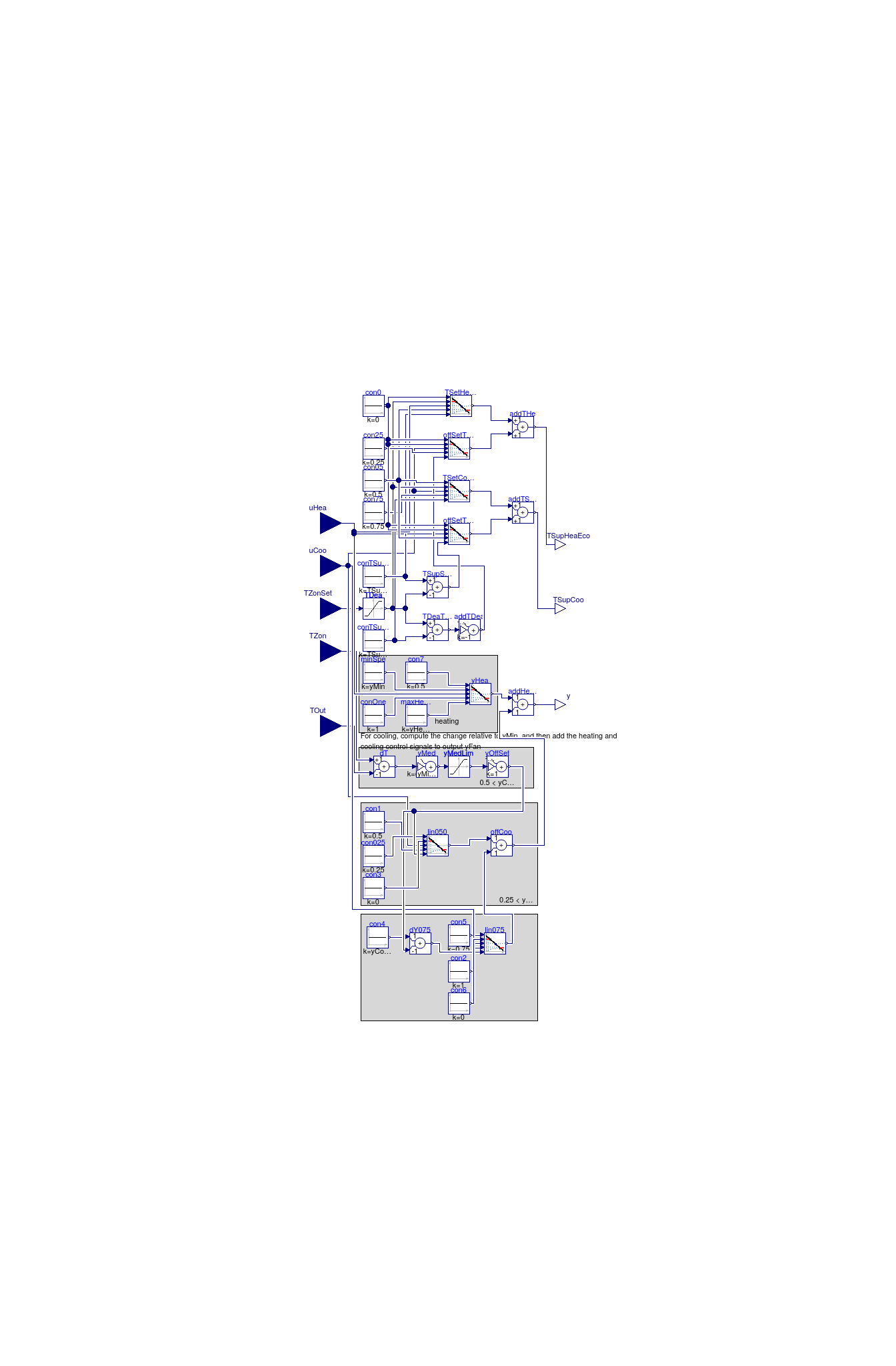
Block that outputs the set points for the supply air temperature for
cooling, heating and economizer control,
and the fan speed for a single zone VAV system.
For the temperature set points, the
parameters are the maximum supply air temperature TSupSetMax,
and the minimum supply air temperature for cooling TSupSetMin.
The deadband temperature is equal to the
average set point for the zone temperature
for heating and cooling, as obtained from the input TZonSet,
constraint to be within 21°C (≈70 F) and
24°C (≈75 F).
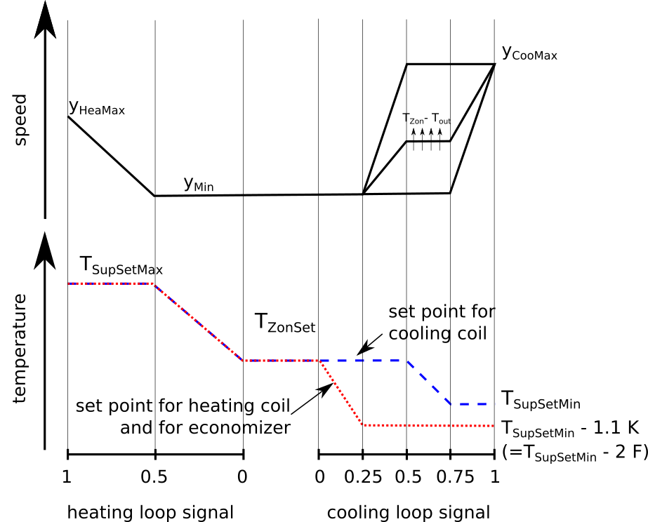
The setpoints are computed as shown in the figure below.
Note that the setpoint for the supply air temperature for heating
and for economizer control is the same, and this setpoint is
lower than TSupSetMin when the heating loop signal
is zero and the economizer is in cooling mode, as shown in the figure.
For the fan speed set point, the
parameters are the maximu fan speed at heating yHeaMax,
the minimum fan speed yMin and
the maximum fan speed for cooling yCooMax.
For a cooling control signal of uCoo > 0.25,
the speed is faster increased the larger the difference is between
the zone temperature minus outdoor temperature TZon-TOut.
The figure below shows the sequence.
The output TSupCoo is to be used to control the cooling coil,
and the output
TSupHeaEco is to be used to control the heating coil and the
economizer dampers.
Note that the inputs uHea and uCoo must be computed
based on the same temperature sensors and control loops.
Parameters
| Type | Name | Default | Description |
|---|
| Temperatures |
| Temperature | TSupSetMax | | Maximum supply air temperature for heating [K] |
| Temperature | TSupSetMin | | Minimum supply air temperature for cooling [K] |
| Speed |
| Real | yHeaMax | yHeaMax( ... | Maximum fan speed for heating [1] |
| Real | yMin | yMin( mi... | Minimum fan speed [1] |
| Real | yCooMax | 1 | Maximum fan speed for cooling [1] |
Connectors
| Type | Name | Description |
|---|
| input RealInput | uHea | Heating control signal [1] |
| input RealInput | uCoo | Cooling control signal [1] |
| input RealInput | TZonSet | Average of heating and cooling setpoints for zone temperature [K] |
| input RealInput | TZon | Zone temperature [K] |
| input RealInput | TOut | Outdoor air temperature [K] |
| output RealOutput | TSupHeaEco | Temperature setpoint for heating coil and for economizer [K] |
| output RealOutput | TSupCoo | Cooling supply air temperature setpoint [K] |
| output RealOutput | y | Fan speed [1] |
Modelica definition
block Supply
parameter Modelica.SIunits.Temperature TSupSetMax
;
parameter Modelica.SIunits.Temperature TSupSetMin
;
parameter Real yHeaMax(min=0, max=1, unit="1")
;
parameter Real yMin(min=0, max=1, unit="1")
;
parameter Real yCooMax(min=0, max=1, unit="1") = 1
;
Buildings.Controls.OBC.CDL.Interfaces.RealInput uHea(min=0, max=1, unit="1")
;
Buildings.Controls.OBC.CDL.Interfaces.RealInput uCoo(min=0, max=1, unit="1")
;
Buildings.Controls.OBC.CDL.Interfaces.RealInput TZonSet(unit="K", displayUnit="degC")
;
Buildings.Controls.OBC.CDL.Interfaces.RealInput TZon(unit="K", displayUnit="degC")
;
Buildings.Controls.OBC.CDL.Interfaces.RealInput TOut(unit="K", displayUnit="degC")
;
Buildings.Controls.OBC.CDL.Interfaces.RealOutput TSupHeaEco(unit="K", displayUnit="degC")
;
Buildings.Controls.OBC.CDL.Interfaces.RealOutput TSupCoo(unit="K", displayUnit="degC")
;
Buildings.Controls.OBC.CDL.Interfaces.RealOutput y(min=0, max=1, unit="1") ;
protected
Buildings.Controls.OBC.CDL.Continuous.Line TSetCooHig
;
Buildings.Controls.OBC.CDL.Continuous.Line offSetTSetHea
;
Buildings.Controls.OBC.CDL.Continuous.Add addTHe ;
Buildings.Controls.OBC.CDL.Continuous.Line offSetTSetCoo
;
Buildings.Controls.OBC.CDL.Continuous.Add addTSupCoo ;
Buildings.Controls.OBC.CDL.Continuous.Add dT(
final k2=-1) ;
Buildings.Controls.OBC.CDL.Continuous.AddParameter yMed(
final p=yCooMax - (yMin - yCooMax)/(0.56 - 5.6)*5.6,
final k=(yMin - yCooMax)/(0.56 - 5.6)) ;
Buildings.Controls.OBC.CDL.Continuous.Limiter yMedLim(
final uMax=yCooMax,
final uMin=yMin) ;
Buildings.Controls.OBC.CDL.Continuous.Limiter TDea(
final uMax=24 + 273.15,
final uMin=21 + 273.15)
;
Buildings.Controls.OBC.CDL.Continuous.Line TSetHeaHig
;
Buildings.Controls.OBC.CDL.Continuous.Sources.Constant con0(
final k=0) ;
Buildings.Controls.OBC.CDL.Continuous.Sources.Constant con25(
final k=0.25) ;
Buildings.Controls.OBC.CDL.Continuous.Sources.Constant con05(
final k=0.5) ;
Buildings.Controls.OBC.CDL.Continuous.Sources.Constant con75(
final k=0.75) ;
Buildings.Controls.OBC.CDL.Continuous.Sources.Constant conTSupSetMax(
final k=TSupSetMax) ;
Buildings.Controls.OBC.CDL.Continuous.Sources.Constant conTSupSetMin(
final k=TSupSetMin) ;
Buildings.Controls.OBC.CDL.Continuous.Add TDeaTSupSetMin(
final k2=-1) ;
Buildings.Controls.OBC.CDL.Continuous.AddParameter addTDea(
final p=-1.1,
final k=-1)
;
Buildings.Controls.OBC.CDL.Continuous.Add TSupSetMaxTDea(
final k2=-1) ;
Buildings.Controls.OBC.CDL.Continuous.Line yHea ;
Buildings.Controls.OBC.CDL.Continuous.Line lin050(
final limitBelow=true,
final limitAbove=true)
;
Buildings.Controls.OBC.CDL.Continuous.Sources.Constant con025(
final k=0.25) ;
Buildings.Controls.OBC.CDL.Continuous.Sources.Constant con1(
final k=0.5) ;
Buildings.Controls.OBC.CDL.Continuous.Sources.Constant con2(
final k=1) ;
Buildings.Controls.OBC.CDL.Continuous.Sources.Constant con3(
final k=0) ;
Buildings.Controls.OBC.CDL.Continuous.Sources.Constant con4(
final k=yCooMax - yMin) ;
Buildings.Controls.OBC.CDL.Continuous.Add dY075(
final k2=-1,
final k1=1)
;
Buildings.Controls.OBC.CDL.Continuous.Line lin075(
final limitBelow=true,
final limitAbove=true)
;
Buildings.Controls.OBC.CDL.Continuous.Sources.Constant con5(
final k=0.75) ;
Buildings.Controls.OBC.CDL.Continuous.Sources.Constant con6(
final k=0) ;
Buildings.Controls.OBC.CDL.Continuous.AddParameter yOffSet(
final p=-yMin, k=1)
;
Buildings.Controls.OBC.CDL.Continuous.Add addHeaCoo(
final k1=1,
final k2=1)
;
Buildings.Controls.OBC.CDL.Continuous.Add offCoo(
final k1=1,
final k2=1)
;
Buildings.Controls.OBC.CDL.Continuous.Sources.Constant con7(
final k=0.5)
;
Buildings.Controls.OBC.CDL.Continuous.Sources.Constant minSpe(
final k=yMin)
;
Buildings.Controls.OBC.CDL.Continuous.Sources.Constant conOne(
final k=1)
;
Buildings.Controls.OBC.CDL.Continuous.Sources.Constant maxHeaSpe(
final k=yHeaMax)
;
equation
connect(offSetTSetHea.u, uCoo);
connect(offSetTSetHea.y, addTHe.u2);
connect(addTHe.y, TSupHeaEco);
connect(TSetCooHig.y, addTSupCoo.u1);
connect(offSetTSetCoo.y, addTSupCoo.u2);
connect(TSetCooHig.u, uCoo);
connect(offSetTSetCoo.u, uHea);
connect(addTSupCoo.y, TSupCoo);
connect(dT.u1, TZon);
connect(dT.u2, TOut);
connect(dT.y, yMed.u);
connect(yMedLim.u, yMed.y);
connect(TDea.u, TZonSet);
connect(TDea.y, TSetHeaHig.f1);
connect(con05.y, TSetHeaHig.x2);
connect(conTSupSetMax.y, TSetHeaHig.f2);
connect(uHea, TSetHeaHig.u);
connect(TSetHeaHig.y, addTHe.u1);
connect(con0.y, offSetTSetHea.x1);
connect(con25.y, offSetTSetHea.x2);
connect(con0.y, offSetTSetHea.f1);
connect(TDea.y, TDeaTSupSetMin.u1);
connect(conTSupSetMin.y, TDeaTSupSetMin.u2);
connect(TDeaTSupSetMin.y, addTDea.u);
connect(addTDea.y, offSetTSetHea.f2);
connect(TSetCooHig.x1, con05.y);
connect(TSetCooHig.f1, TDea.y);
connect(TSetCooHig.x2, con75.y);
connect(TSetCooHig.f2, conTSupSetMin.y);
connect(offSetTSetCoo.f1, con0.y);
connect(offSetTSetCoo.x1, con0.y);
connect(offSetTSetCoo.x2, con05.y);
connect(TSupSetMaxTDea.u1, conTSupSetMax.y);
connect(TDea.y, TSupSetMaxTDea.u2);
connect(TSupSetMaxTDea.y, offSetTSetCoo.f2);
connect(uCoo, lin050.u);
connect(dY075.u1, con4.y);
connect(lin075.x2, con2.y);
connect(lin075.x1, con5.y);
connect(uCoo, lin075.u);
connect(yMedLim.y, yOffSet.u);
connect(dY075.u2, yOffSet.y);
connect(offCoo.u1, lin050.y);
connect(offCoo.u2, lin075.y);
connect(offCoo.y, addHeaCoo.u2);
connect(addHeaCoo.y, y);
connect(lin050.x2, con1.y);
connect(con025.y, lin050.x1);
connect(lin050.f2, yOffSet.y);
connect(con3.y, lin050.f1);
connect(dY075.y, lin075.f2);
connect(con6.y, lin075.f1);
connect(TSetHeaHig.x1, con0.y);
connect(con7.y, yHea.x1);
connect(minSpe.y, yHea.f1);
connect(uHea, yHea.u);
connect(conOne.y, yHea.x2);
connect(maxHeaSpe.y, yHea.f2);
connect(yHea.y, addHeaCoo.u1);
end Supply;
 Buildings.Controls.OBC.ASHRAE.G36_PR1.AHUs.SingleZone.VAV.SetPoints.ExhaustDamper
 Buildings.Controls.OBC.ASHRAE.G36_PR1.AHUs.SingleZone.VAV.SetPoints.OutsideAirFlow
 Buildings.Controls.OBC.ASHRAE.G36_PR1.AHUs.SingleZone.VAV.SetPoints.Supply