Buildings.Controls.OBC.Utilities.PIDWithAutotuning
Package with blocks for PID autotuning
Information
This package contains blocks for the PID controller that tune their control gains automatically.
Package Content
| Name | Description |
|---|---|
| Autotuning PID controller with an AMIGO tuner that employs a first-order system model | |
| Package with blocks for PID autotuners | |
| Package with blocks for a relay controller | |
| Package with blocks for identifying a system model of the control process | |
| Package with type definitions | |
| Collection of models that validate the blocks for autotuning PID controllers |
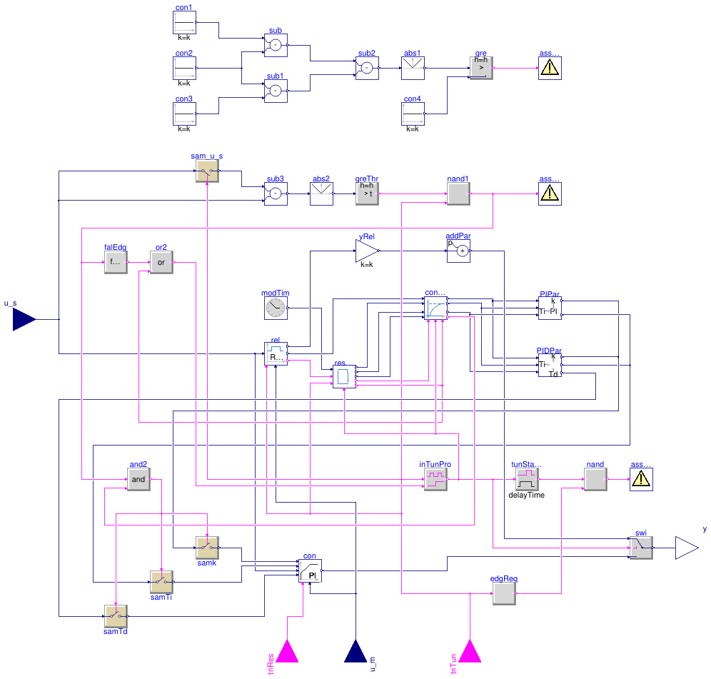
 Buildings.Controls.OBC.Utilities.PIDWithAutotuning.FirstOrderAMIGO
Autotuning PID controller with an AMIGO tuner that employs a first-order system model
Information
This block implements a PI or PID controller with the control gains being tuned by a rule-based method. This rule-based method automatically conducts tuning through the following steps:
Step 1: Introduce a relay disturbance
-
A relay controller
switches the output between two constants (
yHigandyLow), based on the control error e(t) = us(t) - um(t). Details can be found in Buildings.Controls.OBC.Utilities.PIDWithAutotuning.Relay.Controller.
Step 2: Extract parameters of a first-order plus time-delay (FOPTD) model
- Based on the inputs and outputs from the relay controller, the parameters of the FOPTD model is calculated (see Buildings.Controls.OBC.Utilities.PIDWithAutotuning.SystemIdentification). The FOPTD is a simplified representation of the control process.
Step 3: Calculate the PID gains
- The PID gains are calculated with the Approximate M-constrained Integral Gain Optimization (AMIGO) method based on the FOPTD model parameters (see Buildings.Controls.OBC.Utilities.PIDWithAutotuning.AutoTuner.AMIGO).
This block is implemented using
Buildings.Controls.OBC.Utilities.PIDWithInputGains
and inherits most of its configuration. However, through the parameter
controllerType, the controller can only be configured as PI or
PID controller.
Autotuning process
Before the tuning process starts, this block has output from
Buildings.Controls.OBC.Utilities.PIDWithInputGains.
The PID tuning process starts when a request for performing autotuning occurs,
i.e., when the value of the boolean input signal triTun changes from
false to true.
During the tuning process, the block has the output from a relay controller
(see
Buildings.Controls.OBC.Utilities.PIDWithAutotuning.Relay.Controller).
The PID tuning process ends automatically
(see details in
Buildings.Controls.OBC.Utilities.PIDWithAutotuning.BaseClasses.Relay.TunMonitor),
at which point this block reverts the output from the PID controller that uses the
tuned PID parameters.
Note:
-
If an autotuning is ongoing, i.e.,
inTunPro.y = true, a new request for performing autotuning will be ignored and a warning will be generated. - If the set point is changed during an autotuning process, a warning will be generated. The ongoing tuning process will be halted, and no adjustments will be made to the PID parameters.
-
The autotuning must be conducted when the process is in a stable state.
The user should monitor changes in the disturbances affecting the system that
is controlled by the controller, e.g.,outdoor drybulb temperature,
and the controller output
yover time. When the changes in those disturbances are small (e.g., less than 10%) and the change inyis either small or exhibits regular oscillations, the process can be considered in a stable state.
Guidance for setting the parameters
The performance of the autotuning is determined by several parameters, including the
typical range of the control error r,
the reference output for the tuning process yRef, the higher and
lower values for the relay output yHig and yLow, and the
deadband deaBan.
These parameters must be specified on a case-by-case basis.
To set them, the user should conduct the following steps.
Step 1: Conduct a "test run"
- In the test run, disable the autotuning and keep the disturbances and the set point constant.
-
During the test run, adjust
rso that the output of the relay controller,rel.yDif, stays between 0 and 1. - The test run must begin once the simulation reaches a stable state and end when it reaches another stable state.
-
The set point value must lie within the range defined by the
minimum and maximum value of
u_m.
Step 2: Calculate yRef and deaBan
-
Set
yRefto be the ratio of the difference between the set point and the minimum value ofu_mto the range ofu_m, (i.e., the difference between its maximum and minimum values), during the test run. -
For the
deaBan, first divide the maximum and the minimum control errors during the test run byr. Then set thedeaBanto be half of the smaller absolute value of those two deviations.
Step 3: Determine yHig and yLow
-
Adjust
yHigandyLowso that the relay output is asymmetric, i.e.,yHig - yRef ≠ yRef - yLow. -
yHigmust be greater thanyRefbut cannot be greater than 1. -
yLowmust be less thanyRefbut cannot be less than 0.
References
J. Berner (2017). "Automatic Controller Tuning using Relay-based Model Identification." Department of Automatic Control, Lund University.
Parameters
| Type | Name | Default | Description |
|---|---|---|---|
| SimpleController | controllerType | Buildings.Controls.OBC.Utili... | Type of controller |
| Real | r | 1 | Typical range of control error, used for scaling the control error |
| Real | yHig | Higher value for the relay output | |
| Real | yLow | Lower value for the relay output | |
| Real | deaBan | Deadband for holding the relay output | |
| Real | yRef | Reference output for the tuning process. It must be between yLow and yHig | |
| Boolean | reverseActing | true | Set to true for reverse acting, or false for direct acting control action |
| Real | setHys | 0.05*r | Hysteresis for checking set point |
| Initial control gains, used prior to first tuning | |||
| Real | k_start | 1 | Gain of controller used before the first tuning |
| Real | Ti_start | 0.5 | Time constant of integrator block used before the first tuning [s] |
| Real | Td_start | 0.1 | Time constant of derivative block used before the first tuning [s] |
| Limits | |||
| Real | yMax | 1 | Upper limit of output |
| Real | yMin | 0 | Lower limit of output |
| Integrator reset | |||
| Real | y_reset | xi_start | Value to which the controller output is reset if the boolean trigger has a rising edge |
| Advanced | |||
| Integrator anti-windup | |||
| Real | Ni | 0.9 | Ni*Ti is time constant of anti-windup compensation |
| Derivative block | |||
| Real | Nd | 10 | The higher the Nd, the more ideal the derivative block |
| Initialization | |||
| Real | xi_start | 0 | Initial value of integrator state |
| Real | yd_start | 0 | Initial value of derivative output |
Connectors
| Type | Name | Description |
|---|---|---|
| input RealInput | u_s | Connector of set point input signal |
| input RealInput | u_m | Connector of measurement input signal |
| input BooleanInput | triRes | Connector for resetting the controller output |
| input BooleanInput | triTun | Connector for starting the autotuning |
| output RealOutput | y | Connector for actuator output signal |