Package with base classes
Information
This package contains base classes to construct blocks in
Buildings.Controls.OBC.Utilities.PIDWithAutotuning.Relay.
Package Content
| Name |
Description |
 HalfPeriodRatio HalfPeriodRatio
|
Calculate the half period ratio of a response of a relay controller |
 NormalizedTimeDelay NormalizedTimeDelay
|
Calculate the normalized time delay of the response of a relay controller |
 OnOffPeriod OnOffPeriod
|
Calculate the lengths of the on period and the off period |
 SamplerWithResetThreshold SamplerWithResetThreshold
|
Sampler with a reset and a threshold |
 TuningMonitor TuningMonitor
|
Monitor the tuning process |
 Validation Validation
|
Collection of validation models |
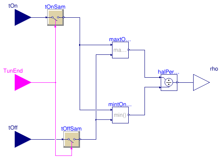
Calculate the half period ratio of a response of a relay controller
Information
This block calculates the half-period ratio of the output from a relay controller.
ρ = max(ton,toff)/ min(ton,toff),
where ton and toff are the
lengths of the on period and the off period, respectively.
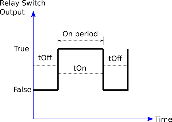
An On period is defined as the period when the relay switch output of the relay controller is
true.
Likewise, an Off period is defined as the period when the relay switch output is false.
See details of the relay switch output in
Buildings.Controls.OBC.Utilities.PIDWithAutotuning.Relay.Controller.
References
J. Berner (2017).
"Automatic Controller Tuning using Relay-based Model Identification."
Department of Automatic Control, Lund University.
Connectors
| Type | Name | Description |
|---|
| input RealInput | tOn | Length for the on period [s] |
| input RealInput | tOff | Length for the off period [s] |
| input BooleanInput | TunEnd | True: the tuning process ends |
| output RealOutput | rho | Real signal of the half period ratio |
Modelica definition
block HalfPeriodRatio
Buildings.Controls.OBC.CDL.Interfaces.RealInput tOn(
final quantity="Time",
final unit="s",
min=100*Buildings.Controls.OBC.CDL.Constants.eps)
;
Buildings.Controls.OBC.CDL.Interfaces.RealInput tOff(
final quantity="Time",
final unit="s",
min=100*Buildings.Controls.OBC.CDL.Constants.eps)
;
Buildings.Controls.OBC.CDL.Interfaces.BooleanInput TunEnd
;
Buildings.Controls.OBC.CDL.Interfaces.RealOutput rho
;
protected
Buildings.Controls.OBC.CDL.Discrete.TriggeredSampler tOnSam(
final y_start=Buildings.Controls.OBC.CDL.Constants.eps)
;
Buildings.Controls.OBC.CDL.Discrete.TriggeredSampler tOffSam(
final y_start=Buildings.Controls.OBC.CDL.Constants.eps)
;
Buildings.Controls.OBC.CDL.Reals.Min mintOntOff
;
Buildings.Controls.OBC.CDL.Reals.Max maxtOntOff
;
Buildings.Controls.OBC.CDL.Reals.Divide halPerRat
;
equation
connect(tOnSam.u, tOn);
connect(tOffSam.u, tOff);
connect(tOnSam.y, maxtOntOff.u1);
connect(maxtOntOff.u2, tOffSam.y);
connect(mintOntOff.u2, tOffSam.y);
connect(maxtOntOff.y, halPerRat.u1);
connect(halPerRat.u2, mintOntOff.y);
connect(halPerRat.y, rho);
connect(tOnSam.y, mintOntOff.u1);
connect(tOnSam.trigger, TunEnd);
connect(TunEnd, tOffSam.trigger);
end HalfPeriodRatio;
Calculate the normalized time delay of the response of a relay controller
Information
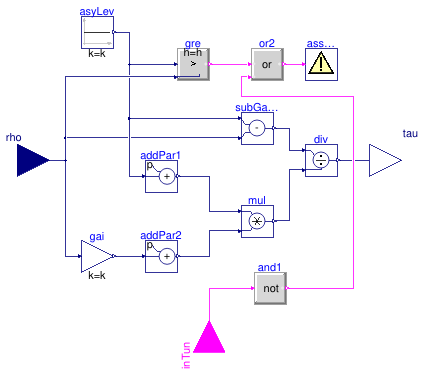
This block calculates the normalized time delay of the output from a relay controller.
τ = (γ - ρ)/(γ - 1)/(ρ*0.35+0.65),
where γ and ρ are the asymmetry level of
the relay controller and the half-period ratio, respectively.
References
J. Berner (2017).
"Automatic Controller Tuning using Relay-based Model Identification."
Department of Automatic Control, Lund University.
Parameters
| Type | Name | Default | Description |
|---|
| Real | gamma | 4 | Asymmetry level of the relay controller |
Connectors
Modelica definition
block NormalizedTimeDelay
parameter Real gamma(min=1+1E-6) = 4
;
Buildings.Controls.OBC.CDL.Interfaces.RealInput rho
;
Buildings.Controls.OBC.CDL.Interfaces.BooleanInput inTun
;
Buildings.Controls.OBC.CDL.Interfaces.RealOutput tau
;
protected
Buildings.Controls.OBC.CDL.Reals.AddParameter addPar1(
final p=-1)
;
Buildings.Controls.OBC.CDL.Reals.AddParameter addPar2(
final p=0.65)
;
Buildings.Controls.OBC.CDL.Reals.Sources.Constant asyLev(
final k=gamma)
;
Buildings.Controls.OBC.CDL.Reals.Divide div
;
Buildings.Controls.OBC.CDL.Reals.Subtract subGamRho
;
Buildings.Controls.OBC.CDL.Reals.MultiplyByParameter gai(
final k=0.35)
;
Buildings.Controls.OBC.CDL.Reals.Multiply mul
;
Buildings.Controls.OBC.CDL.Utilities.Assert assMes(
final message="Warning: the asymmetry level of the relay controller is lower than the half period ratio. Increase the asymmetry level.")
;
Buildings.Controls.OBC.CDL.Reals.Greater gre(
final h=1e-6)
;
Buildings.Controls.OBC.CDL.Logical.Or or2
;
Buildings.Controls.OBC.CDL.Logical.Not and1
;
equation
connect(subGamRho.u1, asyLev.y);
connect(subGamRho.u2, rho);
connect(gai.u, rho);
connect(div.u1, subGamRho.y);
connect(div.u2, mul.y);
connect(div.y, tau);
connect(gai.y, addPar2.u);
connect(addPar2.y, mul.u2);
connect(addPar1.u, asyLev.y);
connect(addPar1.y, mul.u1);
connect(asyLev.y, gre.u1);
connect(rho, gre.u2);
connect(gre.y, or2.u1);
connect(and1.u, inTun);
connect(and1.y, or2.u2);
connect(or2.y, assMes.u);
end NormalizedTimeDelay;
Calculate the lengths of the on period and the off period
Information
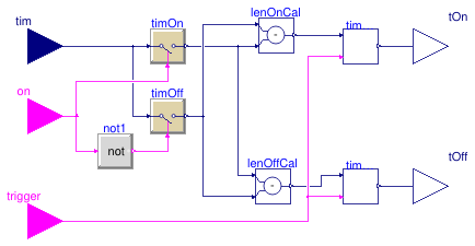
This block processes a relay switch output and calculates the length of
the on period, tOn, and the length of the off period, tOff, as shown below.
Note that tOn is sampled when the relay switch output becomes false.
Likewise, tOff is sampled when the relay switch output becomes true.
References
J. Berner (2017).
"Automatic Controller Tuning using Relay-based Model Identification."
Department of Automatic Control, Lund University.
Connectors
| Type | Name | Description |
|---|
| input RealInput | tim | Simulation time [s] |
| input BooleanInput | on | Relay switch signal |
| input BooleanInput | trigger | Reset the output when trigger becomes true |
| output RealOutput | tOff | Length for the off period [s] |
| output RealOutput | tOn | Length for the on period [s] |
Modelica definition
block OnOffPeriod
Buildings.Controls.OBC.CDL.Interfaces.RealInput tim(
final quantity="Time",
final unit="s")
;
Buildings.Controls.OBC.CDL.Interfaces.BooleanInput on
;
Buildings.Controls.OBC.CDL.Interfaces.BooleanInput trigger
;
Buildings.Controls.OBC.CDL.Interfaces.RealOutput tOff(
final quantity="Time",
final unit="s",
min=100*Buildings.Controls.OBC.CDL.Constants.eps)
;
Buildings.Controls.OBC.CDL.Interfaces.RealOutput tOn(
final quantity="Time",
final unit="s",
min=100*Buildings.Controls.OBC.CDL.Constants.eps)
;
protected
Buildings.Controls.OBC.CDL.Discrete.TriggeredSampler timOn
;
Buildings.Controls.OBC.CDL.Discrete.TriggeredSampler timOff
;
Buildings.Controls.OBC.CDL.Reals.Subtract lenOffCal
;
Buildings.Controls.OBC.CDL.Reals.Subtract lenOnCal
;
Buildings.Controls.OBC.CDL.Logical.Not not1
;
Buildings.Controls.OBC.Utilities.PIDWithAutotuning.Relay.BaseClasses.SamplerWithResetThreshold
timOnRec(
final lowLim=0,
final y_reset=0)
;
Buildings.Controls.OBC.Utilities.PIDWithAutotuning.Relay.BaseClasses.SamplerWithResetThreshold
timOffRec(
final lowLim=0,
final y_reset=0)
;
equation
connect(lenOffCal.u1, timOn.y);
connect(lenOnCal.u2, timOn.y);
connect(lenOnCal.u1, timOff.y);
connect(lenOffCal.u2, timOff.y);
connect(timOn.u, tim);
connect(timOff.u, tim);
connect(timOn.trigger, on);
connect(not1.u, on);
connect(not1.y, timOff.trigger);
connect(timOnRec.y, tOn);
connect(timOffRec.y, tOff);
connect(lenOnCal.y, timOnRec.u);
connect(lenOffCal.y, timOffRec.u);
connect(timOnRec.trigger, trigger);
connect(timOffRec.trigger, trigger);
end OnOffPeriod;
Sampler with a reset and a threshold
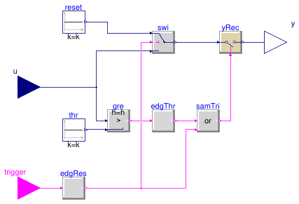
Information
This block samples the input real signal u when u is
larger than a threshold.
On the other hand, when the input boolean signal trigger becomes true,
the output y is reset to a default value.
Parameters
| Type | Name | Default | Description |
|---|
| Real | lowLim | 1 | Lower limit for triggering the sampling |
| Real | y_reset | 1 | The value of y when the reset occurs |
Connectors
| Type | Name | Description |
|---|
| input RealInput | u | Input real signal |
| input BooleanInput | trigger | Reset the output when trigger becomes true |
| output RealOutput | y | Sampling output |
Modelica definition
block SamplerWithResetThreshold
parameter Real lowLim = 1
;
parameter Real y_reset = 1
;
Buildings.Controls.OBC.CDL.Interfaces.RealInput u
;
Buildings.Controls.OBC.CDL.Interfaces.BooleanInput trigger
;
Buildings.Controls.OBC.CDL.Interfaces.RealOutput y
;
protected
Buildings.Controls.OBC.CDL.Reals.Sources.Constant thr(
final k=lowLim)
;
Buildings.Controls.OBC.CDL.Discrete.TriggeredSampler yRec(
final y_start=y_reset)
;
Buildings.Controls.OBC.CDL.Reals.Sources.Constant reset(
final k=y_reset)
;
Buildings.Controls.OBC.CDL.Logical.Or samTri ;
Buildings.Controls.OBC.CDL.Reals.Greater gre
;
Buildings.Controls.OBC.CDL.Reals.Switch swi
;
Buildings.Controls.OBC.CDL.Logical.Edge edgRes(
final pre_u_start=false)
;
Buildings.Controls.OBC.CDL.Logical.Edge edgThr(
final pre_u_start=false)
;
equation
connect(yRec.y, y);
connect(thr.y, gre.u2);
connect(gre.u1, u);
connect(yRec.u, swi.y);
connect(edgRes.u, trigger);
connect(edgRes.y, swi.u2);
connect(swi.u3, u);
connect(swi.u1, reset.y);
connect(samTri.u2, edgRes.y);
connect(samTri.y, yRec.trigger);
connect(edgThr.y, samTri.u1);
connect(edgThr.u, gre.y);
end SamplerWithResetThreshold;
Monitor the tuning process
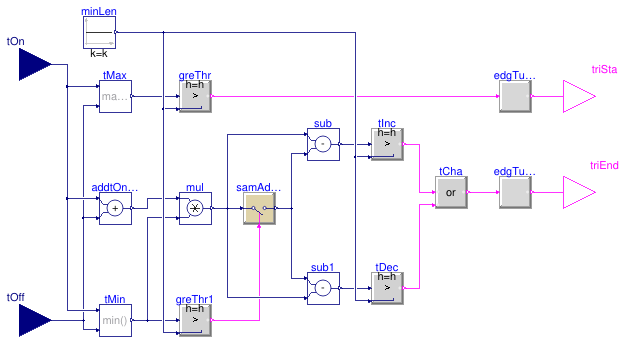
Information
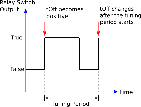
This block detects when a PID tuning period should start and end.
Specifically, the tuning period is triggered to begin when either tOn
or tOff becomes greater than 0.
The tuning period is triggered to end when either tOn
or tOff changes after the tuning period starts, as illustrated below:
References
J. Berner (2017).
"Automatic Controller Tuning using Relay-based Model Identification."
Department of Automatic Control, Lund University.
Connectors
| Type | Name | Description |
|---|
| input RealInput | tOn | Length for the on period [s] |
| input RealInput | tOff | Length for the off period [s] |
| output BooleanOutput | triSta | A boolean signal, true if the tuning starts |
| output BooleanOutput | triEnd | A boolean signal, true if the tuning completes |
Modelica definition
block TuningMonitor
constant Modelica.Units.SI.Time minHorLen = Buildings.Controls.OBC.CDL.Constants.eps
;
Buildings.Controls.OBC.CDL.Interfaces.RealInput tOn(
final quantity="Time",
final unit="s",
min=100*Buildings.Controls.OBC.CDL.Constants.eps)
;
Buildings.Controls.OBC.CDL.Interfaces.RealInput tOff(
final quantity="Time",
final unit="s",
min=100*Buildings.Controls.OBC.CDL.Constants.eps)
;
Buildings.Controls.OBC.CDL.Interfaces.BooleanOutput triSta
;
Buildings.Controls.OBC.CDL.Interfaces.BooleanOutput triEnd
;
protected
Buildings.Controls.OBC.CDL.Reals.Max tMax
;
Buildings.Controls.OBC.CDL.Reals.Greater greThr
;
Buildings.Controls.OBC.CDL.Reals.Sources.Constant minLen(
final k=minHorLen)
;
Buildings.Controls.OBC.CDL.Discrete.TriggeredSampler samAddtOntOff
;
Buildings.Controls.OBC.CDL.Reals.Greater tInc
;
Buildings.Controls.OBC.CDL.Reals.Add addtOntOff
;
Buildings.Controls.OBC.CDL.Reals.Greater tDec
;
Buildings.Controls.OBC.CDL.Logical.Or tCha
;
Buildings.Controls.OBC.CDL.Logical.Edge edgTunSta
;
Buildings.Controls.OBC.CDL.Logical.Edge edgTunEnd
;
Buildings.Controls.OBC.CDL.Reals.Multiply mul
;
Buildings.Controls.OBC.CDL.Reals.Min tMin
;
Buildings.Controls.OBC.CDL.Reals.Greater greThr1
;
Buildings.Controls.OBC.CDL.Reals.Subtract sub ;
Buildings.Controls.OBC.CDL.Reals.Subtract sub1 ;
equation
connect(tMax.u1, tOn);
connect(tMax.u2, tOff);
connect(addtOntOff.u2, tOff);
connect(addtOntOff.u1, tOn);
connect(edgTunSta.y, triSta);
connect(tCha.y, edgTunEnd.u);
connect(edgTunEnd.y, triEnd);
connect(tMin.u1, tOn);
connect(tMin.u2, tOff);
connect(greThr.y, edgTunSta.u);
connect(greThr1.y, samAddtOntOff.trigger);
connect(addtOntOff.y, mul.u1);
connect(mul.u2, tMin.y);
connect(samAddtOntOff.u, mul.y);
connect(tInc.y, tCha.u1);
connect(tDec.y, tCha.u2);
connect(samAddtOntOff.y, sub.u2);
connect(mul.y, sub.u1);
connect(samAddtOntOff.y, sub1.u1);
connect(mul.y, sub1.u2);
connect(tMax.y, greThr.u1);
connect(tMin.y, greThr1.u1);
connect(minLen.y, greThr.u2);
connect(minLen.y, greThr1.u2);
connect(sub.y, tInc.u1);
connect(sub1.y, tDec.u1);
connect(minLen.y, tInc.u2);
connect(minLen.y, tDec.u2);
end TuningMonitor;
 Buildings.Controls.OBC.Utilities.PIDWithAutotuning.Relay.BaseClasses.HalfPeriodRatio
 Buildings.Controls.OBC.Utilities.PIDWithAutotuning.Relay.BaseClasses.NormalizedTimeDelay
 Buildings.Controls.OBC.Utilities.PIDWithAutotuning.Relay.BaseClasses.OnOffPeriod
 Buildings.Controls.OBC.Utilities.PIDWithAutotuning.Relay.BaseClasses.SamplerWithResetThreshold
 Buildings.Controls.OBC.Utilities.PIDWithAutotuning.Relay.BaseClasses.TuningMonitor