This package contains component models that are used to construct the control system in Buildings.Examples.ChillerPlant.
Extends from Modelica.Icons.VariantsPackage (Icon for package containing variants).
| Name | Description |
|---|---|
| Control unit for enabling/disabling chiller | |
| Output y=k-u | |
| A two-pieces linear piecewise function | |
| Count the number of actuators that have request | |
| Trim and respond logic | |
| Control unit for WSE | |
| Zero order hold for boolean variable | |
| Test of components |
 Buildings.Examples.ChillerPlant.BaseClasses.Controls.ChillerSwitch
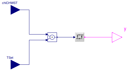
TChi_CHWST > TChiSet + TDeaBan
TChi_CHWST ≤ TChiSet
TChi_CHWST is chiller chilled water supply temperature, TChiSet is set temperature for chilled water leaving chiller, and TDeaBan is dead band to prevent short cycling.
Extends from Modelica.Blocks.Interfaces.BlockIcon (Basic graphical layout of input/output block).
| Type | Name | Default | Description |
|---|---|---|---|
| Temperature | deaBan | Dead band of temperature to prevent chiller short cycling [K] |
| Type | Name | Description |
|---|---|---|
| input RealInput | chiCHWST | Chiller chilled water supply temperature (water entering chiller) [K] |
| output BooleanOutput | y | Control signal for chiller. 1: Enable, 0: Disable |
| input RealInput | TSet | Set temperature of chiller [K] |
block ChillerSwitch "Control unit for enabling/disabling chiller" extends Modelica.Blocks.Interfaces.BlockIcon;Modelica.Blocks.Interfaces.RealInput chiCHWST( final quantity="Temperature", final unit="K", displayUnit="deg") "Chiller chilled water supply temperature (water entering chiller)"; Modelica.Blocks.Interfaces.BooleanOutput y "Control signal for chiller. 1: Enable, 0: Disable"; Modelica.Blocks.Interfaces.RealInput TSet( final quantity="Temperature", final unit="K", displayUnit="deg") "Set temperature of chiller"; parameter Modelica.SIunits.Temperature deaBan "Dead band of temperature to prevent chiller short cycling";Modelica.Blocks.Logical.Hysteresis hysteresis(uLow=0, uHigh=deaBan); Modelica.Blocks.Math.Add add(k1=+1, k2=-1); equationconnect(hysteresis.y, y); connect(chiCHWST, add.u1); connect(TSet, add.u2); connect(add.y, hysteresis.u); end ChillerSwitch;
 Buildings.Examples.ChillerPlant.BaseClasses.Controls.KMinusU

y = k - u.
Extends from Modelica.Blocks.Interfaces.BlockIcon (Basic graphical layout of input/output block).
| Type | Name | Default | Description |
|---|---|---|---|
| Real | k | Sum of u and y |
| Type | Name | Description |
|---|---|---|
| input RealInput | u | Input |
| output RealOutput | y | Output |
block KMinusU "Output y=k-u" extends Modelica.Blocks.Interfaces.BlockIcon; public parameter Real k "Sum of u and y";Modelica.Blocks.Interfaces.RealInput u "Input"; Modelica.Blocks.Interfaces.RealOutput y "Output"; equation y = k - u;end KMinusU;
 Buildings.Examples.ChillerPlant.BaseClasses.Controls.LinearPiecewiseTwo
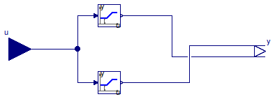
This component calcuates the output according to two piecewise linear function as
| u ∈ [x0, x1]: | y1 = y10 + u (y11-y10)/(x1-x0) y2 = y20 |
| u ∈ (x1, x2]: | y1 = y11 y2 = y20 + (u-x1) (y21-y20)/(x2-x1) |
Extends from Modelica.Blocks.Interfaces.BlockIcon (Basic graphical layout of input/output block).
| Type | Name | Default | Description |
|---|---|---|---|
| Real | x0 | First interval [x0, x1] | |
| Real | x1 | First interval [x0, x1] and second interval (x1, x2] | |
| Real | x2 | Second interval (x1, x2] | |
| Real | y10 | y[1] at u = x0 | |
| Real | y11 | y[1] at u = x1 | |
| Real | y20 | y[2] at u = x1 | |
| Real | y21 | y[2] at u = x2 |
| Type | Name | Description |
|---|---|---|
| input RealInput | u | Set point |
| output RealOutput | y[2] | Connectors of Real output signal |
block LinearPiecewiseTwo "A two-pieces linear piecewise function" extends Modelica.Blocks.Interfaces.BlockIcon; parameter Real x0 "First interval [x0, x1]"; parameter Real x1 "First interval [x0, x1] and second interval (x1, x2]"; parameter Real x2 "Second interval (x1, x2]"; parameter Real y10 "y[1] at u = x0"; parameter Real y11 "y[1] at u = x1"; parameter Real y20 "y[2] at u = x1"; parameter Real y21 "y[2] at u = x2";Modelica.Blocks.Interfaces.RealInput u "Set point"; Modelica.Blocks.Interfaces.RealOutput y[2] "Connectors of Real output signal"; Buildings.Controls.SetPoints.Table y1Tab(table=[x0, y10; x1, y11; x2, y11]) "Tabel for y[1]"; Buildings.Controls.SetPoints.Table y2Tab(table=[x0, y20; x1, y20; x2, y21]) "Tabel for y[2]"; equationconnect(u, y1Tab.u); connect(u, y2Tab.u); connect(y1Tab.y, y[1]); connect(y2Tab.y, y[2]); end LinearPiecewiseTwo;
 Buildings.Examples.ChillerPlant.BaseClasses.Controls.RequestCounter
uAct[i] is larger than uTri.
Extends from Modelica.Blocks.Interfaces.BlockIcon (Basic graphical layout of input/output block).
| Type | Name | Default | Description |
|---|---|---|---|
| Integer | nAct | Number of actuators | |
| Real | uTri | Value to trigger a request from actuator |
| Type | Name | Description |
|---|---|---|
| output IntegerOutput | nInc | Number of actuators requesting control signal increase |
| input RealInput | uAct[nAct] | Input signal from actuators |
block RequestCounter "Count the number of actuators that have request" extends Modelica.Blocks.Interfaces.BlockIcon; parameter Integer nAct "Number of actuators"; parameter Real uTri "Value to trigger a request from actuator";Modelica.Blocks.Interfaces.IntegerOutput nInc "Number of actuators requesting control signal increase"; Modelica.Blocks.Interfaces.RealInput uAct[nAct] "Input signal from actuators"; algorithm nInc := 0; for i in 1:nAct loop if uAct[i] > uTri then nInc := nInc + 1; end if; end for;end RequestCounter;
 Buildings.Examples.ChillerPlant.BaseClasses.Controls.TrimAndRespond
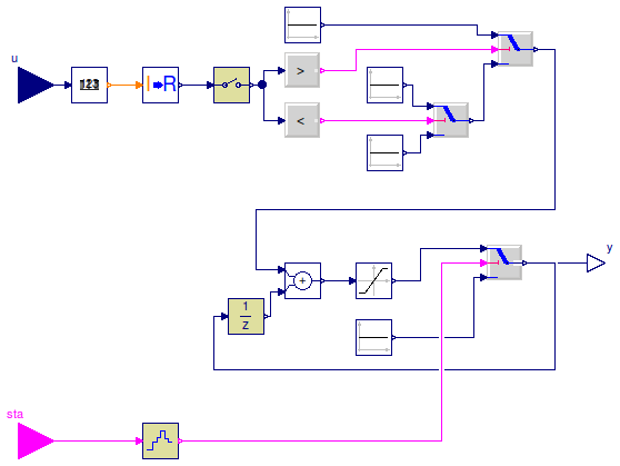
This model implements the trim and respond logic. The model samples the outputs of actuators every tSam.
The control sequence is as follows:
sta = false, then y = yEqu0.sta = true, then,
nReq > nActInc, then y = y + nActInc,nReq < nActDec, then y = y - yDec,y = y.Extends from Modelica.Blocks.Interfaces.DiscreteBlockIcon (Graphical layout of discrete block component icon).
| Type | Name | Default | Description |
|---|---|---|---|
| Integer | n | Number of input singals | |
| Real | uTri | Value to triggering the request for actuator | |
| Real | yEqu0 | y setpoint when equipment starts | |
| Real | yMax | Upper limit for y | |
| Real | yMin | Lower limit for y | |
| Real | yDec | y decrement (must be negative) | |
| Real | yInc | y increment (must be positive) | |
| Integer | nActDec | Number of actuators that can violate setpoints and y is still decreased | |
| Integer | nActInc | Number of actuators requests needed to increase y | |
| Time | tSam | Sample period of component [s] |
| Type | Name | Description |
|---|---|---|
| input RealInput | u[n] | Input singal |
| output RealOutput | y | Connector of Real output signal |
| input BooleanInput | sta | Status indicator, true if equipment is on |
block TrimAndRespond "Trim and respond logic"
  extends Modelica.Blocks.Interfaces.DiscreteBlockIcon;
  parameter Integer n "Number of input singals";
  parameter Real uTri "Value to triggering the request for actuator";
  parameter Real yEqu0 "y setpoint when equipment starts";
  parameter Real yMax "Upper limit for y";
  parameter Real yMin "Lower limit for y";
  parameter Real yDec "y decrement (must be negative)";
  parameter Real yInc "y increment (must be positive)";
  parameter Integer nActDec
    "Number of actuators that can violate setpoints and y is still decreased";
  parameter Integer nActInc "Number of actuators requests needed to increase y";
  Modelica.Blocks.Interfaces.RealInput u[n] "Input singal";
  Modelica.Blocks.Logical.GreaterThreshold incY(threshold=nActInc - 0.5)
    "Outputs true if y needs to be increased";
  Modelica.Blocks.Logical.Switch swi;
  Modelica.Blocks.Discrete.Sampler sam(samplePeriod=tSam) "Sampler";
  parameter Modelica.SIunits.Time tSam "Sample period of component";
  Modelica.Blocks.Sources.Constant conYDec(k=yDec) "y decrease";
  Modelica.Blocks.Math.IntegerToReal intToRea "Convert Integer to Real";
  Modelica.Blocks.Sources.Constant conYInc(k=yInc) "y increase";
  Modelica.Blocks.Discrete.UnitDelay uniDel1(
    samplePeriod=tSam,
    startTime=tSam,
    y_start=yEqu0);
  Modelica.Blocks.Math.Add add;
  Modelica.Blocks.Nonlinear.Limiter lim(uMax=yMax, uMin=yMin) "State limiter";
  Modelica.Blocks.Logical.Switch onSetPoi
    "Set point selecter when equipment switches on";
  Modelica.Blocks.Sources.Constant equSta(k=yEqu0) "equipment start signal";
  Modelica.Blocks.Interfaces.RealOutput y "Connector of Real output signal";
  Modelica.Blocks.Logical.LessThreshold decY(threshold=nActDec + 0.5)
    "Outputs true if y needs to be decreased";
  Modelica.Blocks.Logical.Switch swi1;
  Modelica.Blocks.Sources.Constant zer1(k=0) "Set point when equipment is off";
  Modelica.Blocks.Interfaces.BooleanInput sta
    "Status indicator, true if equipment is on";
  ZeroOrderHold zerOrdHol(samplePeriod=tSam) "Zero order hold";
  Buildings.Examples.ChillerPlant.BaseClasses.Controls.RequestCounter req(uTri=
        uTri, nAct=n) "Count the number of request";
equation
  connect(incY.y, swi.u2);
  connect(sam.y, incY.u);
  connect(uniDel1.y, add.u2);
  connect(add.y, lim.u);
  connect(onSetPoi.y, y);
  connect(zer1.y, swi1.u3);
  connect(swi1.y, swi.u3);
  connect(onSetPoi.y, uniDel1.u);
  connect(sta, zerOrdHol.u);
  connect(req.nInc, intToRea.u);
  connect(intToRea.y, sam.u);
  connect(conYInc.y, swi.u1);
  connect(sam.y, decY.u);
  connect(decY.y, swi1.u2);
  connect(conYDec.y, swi1.u1);
  connect(u, req.uAct);
  connect(equSta.y, onSetPoi.u3);
  connect(lim.y, onSetPoi.u1);
  connect(onSetPoi.u2, zerOrdHol.y);
  connect(swi.y, add.u1);
end TrimAndRespond;
 Buildings.Examples.ChillerPlant.BaseClasses.Controls.WSEControl

This component decides if the WSE is set to on or off. The WSE is enabled when
| Type | Name | Description |
|---|---|---|
| input RealInput | wseCHWST | WSE's chilled water supply temperature (water entering WSE) [K] |
| output RealOutput | y2 | Control signal for valve in CHW loop of WSE |
| input RealInput | TWetBul | Wet bulb temperature [K] |
| input RealInput | towTApp | cooling tower approach [K] |
| input RealInput | wseCWST | WSE's condenser water supply temperature (water entering WSE) [K] |
| output RealOutput | y1 | Control signal for valve in the CW loop of WSE |
block WSEControl "Control unit for WSE"Modelica.Blocks.Interfaces.RealInput wseCHWST( final quantity="Temperature", final unit="K", displayUnit="deg") "WSE's chilled water supply temperature (water entering WSE)"; Modelica.Blocks.Interfaces.RealOutput y2 "Control signal for valve in CHW loop of WSE"; Modelica.Blocks.Sources.Constant TWSEApp(k=1) "Approach for WSE"; Modelica.Blocks.Math.Sum sum(nin=3); Modelica.Blocks.Logical.Greater greater; Modelica.Blocks.Logical.And andOpe; Buildings.Controls.Continuous.OffTimer offTim; Modelica.Blocks.Sources.Constant minDisTim(k=1200) "minium Disabled time for WSE"; Modelica.Blocks.Logical.Less less; Modelica.Blocks.Interfaces.RealInput TWetBul( final quantity="Temperature", final unit="K", displayUnit="deg") "Wet bulb temperature"; Modelica.Blocks.Interfaces.RealInput towTApp( final quantity="Temperature", final unit="K", displayUnit="deg") "cooling tower approach"; Modelica.Blocks.Math.Product pro; Modelica.Blocks.Sources.Constant cons(k=0.9); Modelica.Blocks.Interfaces.RealInput wseCWST( final quantity="Temperature", final unit="K", displayUnit="deg") "WSE's condenser water supply temperature (water entering WSE)"; Modelica.Blocks.Logical.Greater less1; Modelica.Blocks.Sources.Constant cons1(k=1) "cons"; Modelica.Blocks.Sources.Constant minEnaTim(k=1200) "minium enabled time for heat exchanger"; Buildings.Controls.Continuous.OffTimer onTim; Modelica.Blocks.Logical.Greater less2; Modelica.Blocks.Logical.And dis "true for disable"; Modelica.Blocks.Math.Add add1(k1=+1); Modelica.Blocks.Logical.Not not3; Modelica.Blocks.Logical.And and2; Modelica.Blocks.Math.BooleanToReal booToRea; Modelica.Blocks.Logical.Not not1; Modelica.Blocks.Interfaces.RealOutput y1 "Control signal for valve in the CW loop of WSE"; KMinusU kMinU(k=1); Modelica.Blocks.Logical.Pre pre1; equationconnect(sum.y, greater.u2); connect(greater.y, andOpe.u1); connect(minDisTim.y, less.u1); connect(offTim.y, less.u2); connect(less.y, andOpe.u2); connect(TWSEApp.y, sum.u[1]); connect(pro.y, sum.u[2]); connect(cons.y, pro.u1); connect(cons1.y, add1.u1); connect(less1.y, dis.u2); connect(less2.y, dis.u1); connect(minEnaTim.y, less2.u2); connect(onTim.y, less2.u1); connect(not3.y, offTim.u); connect(dis.y, and2.u1); connect(andOpe.y, not1.u); connect(not1.y, and2.u2); connect(kMinU.y, y1); connect(and2.y, pre1.u); connect(pre1.y, booToRea.u); connect(pre1.y, onTim.u); connect(pre1.y, not3.u); connect(booToRea.y, kMinU.u); connect(booToRea.y, y2); connect(TWetBul, pro.u2); connect(wseCHWST, greater.u1); connect(wseCWST, add1.u2); connect(add1.y, less1.u1); connect(wseCHWST, less1.u2); connect(towTApp, sum.u[3]); end WSEControl;
 Buildings.Examples.ChillerPlant.BaseClasses.Controls.ZeroOrderHold

Extends from Modelica.Blocks.Interfaces.BooleanSISO (Single Input Single Output control block with signals of type Boolean), Modelica.Blocks.Interfaces.DiscreteBlock (Base class of discrete control blocks).
| Type | Name | Default | Description |
|---|---|---|---|
| Time | samplePeriod | Sample period of component [s] | |
| Time | startTime | 0 | First sample time instant [s] |
| Type | Name | Description |
|---|---|---|
| input BooleanInput | u | Connector of Boolean input signal |
| output BooleanOutput | y | Connector of Boolean output signal |
block ZeroOrderHold "Zero order hold for boolean variable"
  extends Modelica.Blocks.Interfaces.BooleanSISO;
  extends Modelica.Blocks.Interfaces.DiscreteBlock;
protected
  Boolean ySample;
algorithm
  when {sampleTrigger,initial()} then
    y := ySample;
    ySample := u;
  end when;
end ZeroOrderHold;