Buildings.Templates.Components.Pumps
Pump models
Information
This package contains models for pumps.
Extends from Modelica.Icons.VariantsPackage (Icon for package containing variants).
Package Content
| Name | Description |
|---|---|
| Multiple pumps in parallel | |
| Single pump |
 Buildings.Templates.Components.Pumps.Multiple
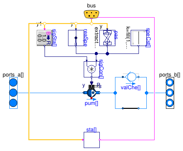
Multiple pumps in parallel

Information
This is a model for a parallel arrangement of nPum pumps
with optional check valves (depending on the value of the parameter
have_valChe).
Note that the inlet and outlet manifolds are not included in this model. The manifolds may be modeled with Buildings.Templates.Components.Routing.MultipleToMultiple. This allows representing both headered and dedicated arrangements.
By default, variable speed pumps are modeled.
Constant speed pumps can be modeled by setting the parameter
have_var to false.
Control points
The following input and output points are available.
-
Pump Start/Stop command (VFD Run or motor starter contact)
y1: DO signal dedicated to each unit, with a dimensionality of one -
Pump speed command (VFD Speed)
yfor variable speed pumps only:-
If
have_varCom: AO signal common to all units, with a dimensionality of zero -
If
not have_varCom: AO signal dedicated to each unit, with a dimensionality of one
-
If
-
Pump status (through VFD interface, VFD status contact,
or current switch)
y1_actual: DI signal dedicated to each unit, with a dimensionality of one
Model parameters
The design parameters and the pump characteristics are specified with an instance of Buildings.Templates.Components.Data.PumpMultiple. The documentation of this record class provides further details on how to properly parameterize the model.
Extends from Buildings.Templates.Components.Interfaces.PartialPumpMultiple (Interface class for multiple pumps in parallel arrangement).
Parameters
| Type | Name | Default | Description |
|---|---|---|---|
| Boolean | addPowerToMedium | false | Set to false to avoid any power (=heat and flow work) being added to medium (may give simpler equations) |
| replaceable package Medium | Water | Medium in the component | |
| PumpMultiple | dat | Design and operating parameters | |
| SpeedControlled_y | pum[nPum] | pum(redeclare each final pac... | Pumps |
| Configuration | |||
| Pump | typ | Buildings.Templates.Componen... | Equipment type |
| Boolean | have_var | true | Set to true for variable speed pump, false for constant speed pump |
| Boolean | have_varCom | true | Set to true for single common speed signal, false for dedicated signals |
| Boolean | have_valChe | true | Set to true to include a check valve in pump line |
| Integer | nPum | Number of pumps | |
| Nominal condition | |||
| PressureDifference | dpValChe_nominal[nPum] | fill(Buildings.Templates.Dat... | Check valve pressure drop at design conditions [Pa] |
| Dynamics | |||
| Nominal condition | |||
| Time | tau | 1 | Time constant of fluid volume for nominal flow, used if energy or mass balance is dynamic [s] |
| Conservation equations | |||
| Dynamics | energyDynamics | Modelica.Fluid.Types.Dynamic... | Type of energy balance: dynamic (3 initialization options) or steady state |
| Assumptions | |||
| Boolean | allowFlowReversal | true | = false to simplify equations, assuming, but not enforcing, no flow reversal |
| Graphics | |||
| Integer | text_rotation | 0 | Text rotation angle in icon layer |
| Boolean | text_flip | false | True to flip text horizontally in icon layer |
| Integer | icon_dy | 300 | Distance in y-direction between each unit in icon layer |
Connectors
| Type | Name | Description |
|---|---|---|
| Bus | bus | Control bus |
| FluidPorts_a | ports_a[nPum] | Vectorized fluid connector a (positive design flow direction is from port(s)_a to port(s)_b) |
| FluidPorts_b | ports_b[nPum] | Vectorized fluid connector b (positive design flow direction is from port(s)_a to port(s)_b) |
Modelica definition
 Buildings.Templates.Components.Pumps.Single
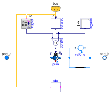
Single pump

Information
This is a model for a single pump
with an optional check valve (depending on the value of the parameter
have_valChe).
By default, a variable speed pump is modeled.
A constant speed pump can be modeled by setting the parameter
have_var to false.
Control points
The following input and output points are available.
-
Pump Start/Stop command (VFD Run or motor starter contact)
y1: DO signal -
Pump speed command (VFD Speed)
yfor variable speed pumps only: AO signal -
Pump status (through VFD interface, VFD status contact,
or current switch)
y1_actual: DI signal
Model parameters
The design parameters and the pump characteristics are specified with an instance of Buildings.Templates.Components.Data.PumpSingle. The documentation of this record class provides further details on how to properly parameterize the model.
Extends from Buildings.Templates.Components.Interfaces.PartialPumpSingle (Interface class for single pump).
Parameters
| Type | Name | Default | Description |
|---|---|---|---|
| Boolean | addPowerToMedium | false | Set to false to avoid any power (=heat and flow work) being added to medium (may give simpler equations) |
| replaceable package Medium | Water | Medium in the component | |
| PumpSingle | dat | Design and operating parameters | |
| SpeedControlled_y | pum | pum(redeclare final package ... | Pump |
| Configuration | |||
| Pump | typ | Buildings.Templates.Componen... | Equipment type |
| Boolean | have_var | true | Set to true for variable speed pump, false for constant speed pump |
| Boolean | have_varCom | true | Set to true for single common speed signal, false for dedicated signals |
| Boolean | have_valChe | true | Set to true to include a check valve in pump line |
| Nominal condition | |||
| PressureDifference | dpValChe_nominal | Buildings.Templates.Data.Def... | Check valve pressure drop at design conditions [Pa] |
| Dynamics | |||
| Nominal condition | |||
| Time | tau | 1 | Time constant of fluid volume for nominal flow, used if energy or mass balance is dynamic [s] |
| Conservation equations | |||
| Dynamics | energyDynamics | Modelica.Fluid.Types.Dynamic... | Type of energy balance: dynamic (3 initialization options) or steady state |
| Assumptions | |||
| Boolean | allowFlowReversal | true | = false to simplify equations, assuming, but not enforcing, no flow reversal |
| Graphics | |||
| Integer | text_rotation | 0 | Text rotation angle in icon layer |
| Boolean | text_flip | false | True to flip text horizontally in icon layer |
| Advanced | |||
| MassFlowRate | m_flow_small | 1E-4*abs(m_flow_nominal) | Small mass flow rate for regularization of zero flow [kg/s] |
| Diagnostics | |||
| Boolean | show_T | false | = true, if actual temperature at port is computed |
Connectors
| Type | Name | Description |
|---|---|---|
| Bus | bus | Control bus |
| FluidPort_a | port_a | Fluid connector a (positive design flow direction is from port_a to port_b) |
| FluidPort_b | port_b | Fluid connector b (positive design flow direction is from port_a to port_b) |
