Buildings.Fluid.FixedResistances
Package with models for fixed flow resistances
Information
This package contains component models for fixed flow resistances. By fixed flow resistance, we mean resistances that do not change the flow coefficient
k = m ⁄ √Δp.
For models of valves and air dampers, see Buildings.Fluid.Actuators. For models of flow resistances as part of the building constructions, see Buildings.Airflow.Multizone.
The model Buildings.Fluid.FixedResistances.PressureDrop is a fixed flow resistance that takes as parameter a nominal flow rate and a nominal pressure drop. The actual resistance is scaled using the above equation.
The model Buildings.Fluid.FixedResistances.HydraulicDiameter is a fixed flow resistance that takes as parameter a nominal flow rate and a hydraulic diameter. The actual resistance is scaled using the above equation.
The model Buildings.Fluid.FixedResistances.LosslessPipe is an ideal pipe segment with no pressure drop. It is primarily used in models in which the above pressure drop model need to be replaced by a model with no pressure drop.
The model Buildings.Fluid.FixedResistances.Junction can be used to model flow splitters or flow merges.
Extends from Modelica.Icons.Package (Icon for standard packages).
Package Content
| Name | Description |
|---|---|
| Check valve that avoids flow reversal | |
| Fixed flow resistance with hydraulic diameter and m_flow as parameter | |
| Flow splitter with fixed resistance at each port | |
| Pipe with no flow friction and no heat transfer | |
| Pipe with finite volume discretization along flow path | |
| Pipe model using spatialDistribution for temperature delay | |
| Discretized pipe model using spatialDistribution for temperature delay | |
| Fixed flow resistance with dp and m_flow as parameter | |
| Package with models for buried pipes | |
| Collection of models that illustrate model use and test models | |
| Collection of validation models | |
| Package with base classes for Buildings.Fluid.FixedResistances |
 Buildings.Fluid.FixedResistances.CheckValve
Check valve that avoids flow reversal

Information
Implementation of a hydraulic check valve. Note that small reverse flows can still occur with this model.
Main equations
The basic flow function
ṁ = sign(Δp) k √ Δp ,
with regularization near the origin, is used to compute the mass flow rate
through the fully closed and fully open valve, respectively.
The valve is considered fully closed when subjected to a negative pressure drop,
and its flow coefficient k is then equal to l * Kv_SI,
where Kv_SI is equal to Kv but in SI units.
The valve is considered fully open when the pressure drop exceeds
dpValve_closing,
and its flow coefficient k is then equal to Kv_SI.
For valve positions between these two extremes, a quintic spline interpolation
is applied to determine the mass flow rate as a function of
the pressure drop across the valve.
Typical use and important parameters
The parameters m_flow_nominal and dpValve_nominal
determine the flow coefficient of the check valve when it is fully open.
The leakage ratio l determines the minimum flow coefficient,
for negative pressure differences.
The parameter dpFixed_nominal allows to include a series
pressure drop with a fixed flow coefficient into the model.
The parameter dpValve_closing determines when the
flow coefficient starts to increase,
which is typically in the order of dpValve_nominal.
Implementation
The check valve implementation approximates the physics
where a forward pressure difference opens the valve such that
the valve opening increases, causing a growing orifice area
and thus increasing the flow coefficient.
Near dp=dpValve_closing, the valve is fully open and the flow coefficient saturates
to the flow coefficient value determined by dpValve_nominal and m_flow_nominal.
For typical valve diameters, the check valve is only fully open
near nominal mass flow rate. Therefore, the model sets dpValve_closing=dpValve_nominal/2
by default.
Extends from Buildings.Fluid.BaseClasses.PartialResistance (Partial model for a hydraulic resistance), Buildings.Fluid.Actuators.BaseClasses.ValveParameters (Model with parameters for valves).
Parameters
| Type | Name | Default | Description |
|---|---|---|---|
| replaceable package Medium | PartialMedium | Medium in the component | |
| MassFlowRate | m_flow_turbulent | deltaM*abs(m_flow_nominal) | Turbulent flow if |m_flow| >= m_flow_turbulent [kg/s] |
| Real | l | 0.001 | Valve leakage, l=Kv(y=0)/Kv(y=1) |
| Real | kFixed | if dpFixed_nominal > Modelic... | Flow coefficient of fixed resistance that may be in series with valve, k=m_flow/sqrt(dp), with unit=(kg.m)^(1/2). |
| Nominal condition | |||
| MassFlowRate | m_flow_nominal | Nominal mass flow rate [kg/s] | |
| PressureDifference | dp_nominal | dpValve_nominal + dpFixed_no... | Pressure drop at nominal mass flow rate [Pa] |
| PressureDifference | dpValve_nominal | Nominal pressure drop of fully open valve, used if CvData=Buildings.Fluid.Types.CvTypes.OpPoint [Pa] | |
| PressureDifference | dpFixed_nominal | 0 | Pressure drop of pipe and other resistances that are in series [Pa] |
| PressureDifference | dpValve_closing | dpValve_nominal/2 | Pressure drop when the check valve starts to close [Pa] |
| Flow Coefficient | |||
| CvTypes | CvData | Buildings.Fluid.Types.CvType... | Selection of flow coefficient |
| Real | Kv | Kv (metric) flow coefficient [m3/h/(bar)^(1/2)] | |
| Real | Cv | Cv (US) flow coefficient [USG/min/(psi)^(1/2)] | |
| Area | Av | Av (metric) flow coefficient [m2] | |
| Pressure-flow linearization | |||
| Real | deltaM | 0.02 | Fraction of nominal flow rate where linearization starts, if y=1 |
| Assumptions | |||
| Boolean | allowFlowReversal | true | = false to simplify equations, assuming, but not enforcing, no flow reversal |
| Advanced | |||
| Boolean | from_dp | true | = true, use m_flow = f(dp) else dp = f(m_flow) |
| Boolean | linearized | false | = true, use linear relation between m_flow and dp for any flow rate |
| Diagnostics | |||
| Boolean | show_T | false | = true, if actual temperature at port is computed |
| Nominal condition | |||
| Density | rhoStd | Medium.density_pTX(101325, 2... | Inlet density for which valve coefficients are defined [kg/m3] |
Connectors
| Type | Name | Description |
|---|---|---|
| FluidPort_a | port_a | Fluid connector a (positive design flow direction is from port_a to port_b) |
| FluidPort_b | port_b | Fluid connector b (positive design flow direction is from port_a to port_b) |
Modelica definition
 Buildings.Fluid.FixedResistances.HydraulicDiameter
Fixed flow resistance with hydraulic diameter and m_flow as parameter
Information
This is a model of a flow resistance with a fixed flow coefficient. The mass flow rate is computed as
ṁ = k √Δp,
where
k is a constant and
Δp is the pressure drop.
The constant k is equal to
k=m_flow_nominal/sqrt(dp_nominal),
where m_flow_nominal is a parameter.
Assumptions
In the region
abs(m_flow) < m_flow_turbulent,
the square root is replaced by a differentiable function
with finite slope.
The value of m_flow_turbulent is
computed as
m_flow_turbulent = eta_nominal*dh/4*π*ReC,
where
eta_nominal is the dynamic viscosity, obtained from
the medium model. The parameter
dh is the hydraulic diameter and
ReC=4000 is the critical Reynolds number, which both
can be set by the user.
Important parameters
By default, the pressure drop at nominal flow rate is computed as
dp_nominal = fac * dpStraightPipe_nominal,
where dpStraightPipe_nominal is a parameter that is automatically computed
based on the
nominal mass flow rate, hydraulic diameter, pipe roughness and medium properties.
The hydraulic diameter dh is by default
computed based on the flow velocity v_nominal and the nominal
mass flow rate m_flow_nominal. Hence, users should change the
default values of dh or v_nominal
if they are not applicable for their model.
The factor fac takes into account additional resistances such as
for bends. The default value of 2 can be changed by the user.
The parameter from_dp is used to determine
whether the mass flow rate is computed as a function of the
pressure drop (if from_dp=true), or vice versa.
This setting can affect the size of the nonlinear system of equations.
If the parameter linearized is set to true,
then the pressure drop is computed as a linear function of the
mass flow rate.
If the parameter disableComputeFlowResistance is set to true,
then the pressure drop is not computed. This allows to aggregate dp_nominal
in other components such as in an actuator using its parameter dpFixed_nominal.
See Buildings.Fluid.Actuators.UsersGuide
for further information on dpFixed_nominal.
Setting allowFlowReversal=false can lead to simpler
equations. However, this should only be set to false
if one can guarantee that the flow never reverses its direction.
This can be difficult to guarantee, as pressure imbalance after
the initialization, or due to medium expansion and contraction,
can lead to reverse flow.
If the parameter
show_T is set to true,
then the model will compute the
temperature at its ports. Note that this can lead to state events
when the mass flow rate approaches zero,
which can increase computing time.
Notes
For more detailed models that compute the actual flow friction,
models from the package
Modelica.Fluid
can be used and combined with models from the
Buildings library.
For a model that uses dp_nominal as a parameter rather than
geoemetric data, use
Buildings.Fluid.FixedResistances.PressureDrop.
Implementation
The pressure drop is computed by calling a function in the package Buildings.Fluid.BaseClasses.FlowModels, This package contains regularized implementations of the equation
ṁ = sign(Δp) k √ Δp
and its inverse function.
To decouple the energy equation from the mass equations, the pressure drop is a function of the mass flow rate, and not the volume flow rate. This leads to simpler equations.
Extends from Buildings.Fluid.FixedResistances.PressureDrop (Fixed flow resistance with dp and m_flow as parameter).
Parameters
| Type | Name | Default | Description |
|---|---|---|---|
| replaceable package Medium | PartialMedium | Medium in the component | |
| Length | dh | sqrt(4*m_flow_nominal/rho_de... | Hydraulic diameter (assuming a round cross section area) [m] |
| Length | length | Length of the pipe [m] | |
| Real | ReC | 4000 | Reynolds number where transition to turbulence starts |
| Length | roughness | 2.5e-5 | Absolute roughness of pipe, with a default for a smooth steel pipe (dummy if use_roughness = false) [m] |
| Real | fac | 2 | Factor to take into account resistance of bends etc., fac=dp_nominal/dpStraightPipe_nominal |
| Nominal condition | |||
| MassFlowRate | m_flow_nominal | Nominal mass flow rate [kg/s] | |
| PressureDifference | dp_nominal | fac*dpStraightPipe_nominal | Pressure drop at nominal mass flow rate [Pa] |
| Velocity | v_nominal | if rho_default < 500 then 1.... | Velocity at m_flow_nominal (used to compute default value for hydraulic diameter dh) [m/s] |
| Transition to laminar | |||
| Real | deltaM | eta_default*dh/4*Modelica.Co... | Fraction of nominal mass flow rate where transition to turbulent occurs |
| Assumptions | |||
| Boolean | allowFlowReversal | true | = false to simplify equations, assuming, but not enforcing, no flow reversal |
| Advanced | |||
| Boolean | from_dp | false | = true, use m_flow = f(dp) else dp = f(m_flow) |
| Boolean | linearized | false | = true, use linear relation between m_flow and dp for any flow rate |
| Boolean | disableComputeFlowResistance | false | =false to disable computation of flow resistance |
| Diagnostics | |||
| Boolean | show_T | false | = true, if actual temperature at port is computed |
Connectors
| Type | Name | Description |
|---|---|---|
| FluidPort_a | port_a | Fluid connector a (positive design flow direction is from port_a to port_b) |
| FluidPort_b | port_b | Fluid connector b (positive design flow direction is from port_a to port_b) |
Modelica definition
 Buildings.Fluid.FixedResistances.Junction
Flow splitter with fixed resistance at each port
Information
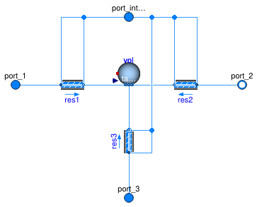
Model of a flow junction with an optional fixed resistance in each flow leg and an optional mixing volume at the junction.
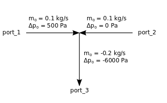
The pressure drop is implemented using the model Buildings.Fluid.FixedResistances.PressureDrop. If its nominal pressure drop is set to zero, then the pressure drop model will be removed. For example, the pressure drop declaration
  m_flow_nominal={ 0.1, 0.1,  -0.2},
  dp_nominal =   {500,    0, -6000}
would model a flow mixer that has the nominal flow rates and associated pressure drops
as shown in the figure below. Note that port_3 is set to negative values.
The negative values indicate that at the nominal conditions, fluid is leaving the component.
If
energyDynamics <> Modelica.Fluid.Types.Dynamics.SteadyState,
then at the flow junction, a fluid volume is modeled.
The fluid volume is implemented using the model
Buildings.Fluid.Delays.DelayFirstOrder.
The fluid volume has the size
V = sum(abs(m_flow_nominal[:])/3)*tau/rho_nominal
where tau is a parameter and rho_nominal is the density
of the medium in the volume at nominal condition.
Setting energyDynamics=Modelica.Fluid.Types.Dynamics.FixedInitial
can help reducing the size of the nonlinear
system of equations.
Extends from Buildings.Fluid.BaseClasses.PartialThreeWayResistance (Flow splitter with partial resistance model at each port).
Parameters
| Type | Name | Default | Description |
|---|---|---|---|
| replaceable package Medium | PartialMedium | Medium in the component | |
| Nominal condition | |||
| MassFlowRate | m_flow_nominal[3] | Mass flow rate. Set negative at outflowing ports. [kg/s] | |
| Pressure | dp_nominal[3] | Pressure drop at nominal mass flow rate, set to zero or negative number at outflowing ports. [Pa] | |
| Transition to laminar | |||
| Real | deltaM | 0.3 | Fraction of nominal mass flow rate where transition to turbulent occurs |
| Dynamics | |||
| Conservation equations | |||
| Dynamics | energyDynamics | Modelica.Fluid.Types.Dynamic... | Type of energy balance: dynamic (3 initialization options) or steady state |
| MassFlowRate | mDyn_flow_nominal | sum(abs(m_flow_nominal[:])/3) | Nominal mass flow rate for dynamic momentum and energy balance [kg/s] |
| Nominal condition | |||
| Time | tau | 10 | Time constant at nominal flow for dynamic energy and momentum balance [s] |
| Advanced | |||
| Boolean | from_dp | true | = true, use m_flow = f(dp) else dp = f(m_flow) |
| PortFlowDirection | portFlowDirection_1 | Modelica.Fluid.Types.PortFlo... | Flow direction for port_1 |
| PortFlowDirection | portFlowDirection_2 | Modelica.Fluid.Types.PortFlo... | Flow direction for port_2 |
| PortFlowDirection | portFlowDirection_3 | Modelica.Fluid.Types.PortFlo... | Flow direction for port_3 |
| Boolean | verifyFlowReversal | false | =true, to assert that the flow does not reverse when portFlowDirection_* does not equal Bidirectional |
| MassFlowRate | m_flow_small | mDyn_flow_nominal*1e-4 | Small mass flow rate for checking flow reversal [kg/s] |
| Boolean | linearized | false | = true, use linear relation between m_flow and dp for any flow rate |
| Initialization | |||
| AbsolutePressure | p_start | Medium.p_default | Start value of pressure [Pa] |
| Temperature | T_start | Medium.T_default | Start value of temperature [K] |
| MassFraction | X_start[Medium.nX] | Medium.X_default | Start value of mass fractions m_i/m [kg/kg] |
| ExtraProperty | C_start[Medium.nC] | fill(0, Medium.nC) | Start value of trace substances |
| ExtraProperty | C_nominal[Medium.nC] | fill(1E-2, Medium.nC) | Nominal value of trace substances. (Set to typical order of magnitude.) |
Connectors
| Type | Name | Description |
|---|---|---|
| FluidPort_a | port_1 | First port, typically inlet |
| FluidPort_b | port_2 | Second port, typically outlet |
| FluidPort_a | port_3 | Third port, can be either inlet or outlet |
Modelica definition
 Buildings.Fluid.FixedResistances.LosslessPipe
Pipe with no flow friction and no heat transfer
Information
Model of a pipe with no flow resistance, no heat loss and no transport delay.
This model can be used to replace a replaceable pipe model
in flow legs in which no friction should be modeled.
This is for example done in the outlet port of the
base class for three way valves,
Buildings.Fluid.Actuators.BaseClasses.PartialThreeWayValve.
Extends from Buildings.Fluid.Interfaces.PartialTwoPortInterface (Partial model with two ports and declaration of quantities that are used by many models).
Parameters
| Type | Name | Default | Description |
|---|---|---|---|
| replaceable package Medium | PartialMedium | Medium in the component | |
| Nominal condition | |||
| MassFlowRate | m_flow_nominal | Nominal mass flow rate [kg/s] | |
| Assumptions | |||
| Boolean | allowFlowReversal | true | = false to simplify equations, assuming, but not enforcing, no flow reversal |
| Advanced | |||
| MassFlowRate | m_flow_small | 1E-4*abs(m_flow_nominal) | Small mass flow rate for regularization of zero flow [kg/s] |
| Diagnostics | |||
| Boolean | show_T | false | = true, if actual temperature at port is computed |
Connectors
| Type | Name | Description |
|---|---|---|
| FluidPort_a | port_a | Fluid connector a (positive design flow direction is from port_a to port_b) |
| FluidPort_b | port_b | Fluid connector b (positive design flow direction is from port_a to port_b) |
Modelica definition
 Buildings.Fluid.FixedResistances.Pipe
Pipe with finite volume discretization along flow path
Information
Model of a pipe with flow resistance and optional heat exchange with environment.
Heat loss calculation
There are two possible configurations:
-
If
useMultipleHeatPorts=false(default option), the pipe uses a single heat port for the heat exchange with the environment. Note that if the heat port is unconnected, then all volumes are still connected through the heat conduction elementsconPipWal. Therefore, they exchange a small amount of heat, which is not physical. To avoid this, setuseMultipleHeatPorts=true. -
If
useMultipleHeatPorts=true, then one heat port for each segment of the pipe is used for the heat exchange with the environment. If the heat port is unconnected, then the pipe has no heat loss.
Pressure drop calculation
The default value for the parameter diameter is computed such that the flow velocity
is equal to v_nominal=0.15 for a mass flow rate of m_flow_nominal.
Both parameters, diameter and v_nominal, can be overwritten
by the user.
The default value for dp_nominal is two times the pressure drop that the pipe
would have if it were straight with no fittings.
The factor of two that takes into account the pressure loss of fittings can be overwritten.
These fittings could also be explicitly modeled outside of this component using models from
the package
Modelica.Fluid.Fittings.
For mass flow rates other than m_flow_nominal, the model
Buildings.Fluid.FixedResistances.PressureDrop is used to
compute the pressure drop.
For a steady-state model of a flow resistance, use Buildings.Fluid.FixedResistances.PressureDrop instead of this model.
Extends from Buildings.Fluid.FixedResistances.BaseClasses.Pipe (Model of a pipe with finite volume discretization along the flow path).
Parameters
| Type | Name | Default | Description |
|---|---|---|---|
| replaceable package Medium | PartialMedium | Medium in the component | |
| Integer | nSeg | 10 | Number of volume segments |
| Length | thicknessIns | Thickness of insulation [m] | |
| ThermalConductivity | lambdaIns | Heat conductivity of insulation [W/(m.K)] | |
| Length | diameter | sqrt(4*m_flow_nominal/rho_de... | Pipe diameter (without insulation) [m] |
| Length | length | Length of the pipe [m] | |
| Velocity | v_nominal | 0.15 | Velocity at m_flow_nominal (used to compute default diameter) [m/s] |
| Length | roughness | 2.5e-5 | Absolute roughness of pipe, with a default for a smooth steel pipe (dummy if use_roughness = false) [m] |
| Boolean | useMultipleHeatPorts | false | = true to use one heat port for each segment of the pipe, false to use a single heat port for the entire pipe |
| Nominal condition | |||
| MassFlowRate | m_flow_nominal | Nominal mass flow rate [kg/s] | |
| PressureDifference | dp_nominal | 2*dpStraightPipe_nominal | Pressure difference [Pa] |
| Dynamics | |||
| Conservation equations | |||
| Dynamics | energyDynamics | Modelica.Fluid.Types.Dynamic... | Type of energy balance: dynamic (3 initialization options) or steady state |
| Real | mSenFac | 1 | Factor for scaling the sensible thermal mass of the volume |
| Advanced | |||
| Dynamics | |||
| Dynamics | massDynamics | energyDynamics | Type of mass balance: dynamic (3 initialization options) or steady state, must be steady state if energyDynamics is steady state |
| MassFlowRate | m_flow_small | 1E-4*abs(m_flow_nominal) | Small mass flow rate for regularization of zero flow [kg/s] |
| Initialization | |||
| AbsolutePressure | p_start | Medium.p_default | Start value of pressure [Pa] |
| Temperature | T_start | Medium.T_default | Start value of temperature [K] |
| MassFraction | X_start[Medium.nX] | Medium.X_default | Start value of mass fractions m_i/m [kg/kg] |
| ExtraProperty | C_start[Medium.nC] | fill(0, Medium.nC) | Start value of trace substances |
| ExtraProperty | C_nominal[Medium.nC] | fill(1E-2, Medium.nC) | Nominal value of trace substances. (Set to typical order of magnitude.) |
| Assumptions | |||
| Boolean | allowFlowReversal | true | = false to simplify equations, assuming, but not enforcing, no flow reversal |
| Flow resistance | |||
| Boolean | from_dp | false | = true, use m_flow = f(dp) else dp = f(m_flow) |
| Boolean | linearizeFlowResistance | false | = true, use linear relation between m_flow and dp for any flow rate |
| Real | deltaM | 0.1 | Fraction of nominal flow rate where flow transitions to laminar |
| Real | ReC | 4000 | Reynolds number where transition to turbulence starts |
Connectors
| Type | Name | Description |
|---|---|---|
| FluidPort_a | port_a | Fluid connector a (positive design flow direction is from port_a to port_b) |
| FluidPort_b | port_b | Fluid connector b (positive design flow direction is from port_a to port_b) |
| HeatPort_a | heatPort | Single heat port that connects to outside of pipe wall (default, enabled when useMultipleHeatPorts=false) |
| HeatPorts_a | heatPorts[nSeg] | Multiple heat ports that connect to outside of pipe wall (enabled if useMultipleHeatPorts=true) |
Modelica definition
 Buildings.Fluid.FixedResistances.PlugFlowPipe
Pipe model using spatialDistribution for temperature delay
Information
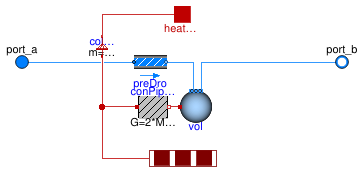
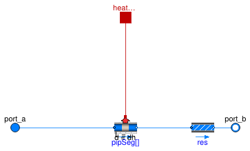
Pipe with heat loss using the time delay based heat losses and transport of the fluid using a plug flow model, applicable for simulation of long pipes such as in district heating and cooling systems.
This model takes into account transport delay along the pipe length idealized as a plug flow. The model also includes thermal inertia of the pipe wall.
Implementation
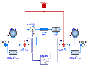
The
spatialDistribution operator is used for the temperature wave propagation
through the length of the pipe. This operator is contained in
Buildings.Fluid.FixedResistances.BaseClasses.PlugFlow.
The model Buildings.Fluid.FixedResistances.BaseClasses.PlugFlowHeatLoss implements a heat loss in design direction, but leaves the enthalpy unchanged in opposite flow direction. Therefore it is used in front of and behind the time delay.
The pressure drop is implemented using Buildings.Fluid.FixedResistances.HydraulicDiameter.
The thermal capacity of the pipe wall is implemented as a mixing volume
of the fluid in the pipe, of which the thermal capacity is equal to that
of the pipe wall material.
In addition, this mixing volume allows the hydraulic separation of subsequent pipes.
The mixing volume is either split between the inlet and outlet ports
(port_a and port_b) or lumped in at the outlet (port_b)
if have_symmetry is set to false.
This mixing volume can be removed from this model with the Boolean parameter
have_pipCap, in cases where the pipe wall heat capacity
is negligible and a state is not needed at the pipe outlet
(see the note below about numerical Jacobians).
Note that in order to model a branched network it is recommended to use
Buildings.Fluid.FixedResistances.Junction at each junction and to configure
that junction model with a state
(energyDynamics <> Modelica.Fluid.Types.Dynamics.SteadyState),
see for instance
Buildings.Fluid.FixedResistances.Validation.PlugFlowPipes.PlugFlowAIT.
This will avoid the numerical Jacobian that is otherwise created when
the inlet ports of two instances of the plug flow model are connected together.
Assumptions
- Heat losses are for steady-state operation.
- The axial heat diffusion in the fluid, the pipe wall and the ground are neglected.
- The boundary temperature is uniform.
-
The thermal inertia of the pipe wall material is lumped on the side of the pipe
that is connected to
port_b.
References
Full details on the model implementation and experimental validation can be found in:
van der Heijde, B., Fuchs, M., Ribas Tugores, C., Schweiger, G., Sartor, K.,
Basciotti, D., Müller, D., Nytsch-Geusen, C., Wetter, M. and Helsen, L.
(2017).
Dynamic equation-based thermo-hydraulic pipe model for district heating and
cooling systems.
Energy Conversion and Management, vol. 151, p. 158-169.
doi:
10.1016/j.enconman.2017.08.072.
Extends from Buildings.Fluid.FixedResistances.BaseClasses.PlugFlowPipe (Pipe model using spatialDistribution for temperature delay).
Parameters
| Type | Name | Default | Description |
|---|---|---|---|
| replaceable package Medium | PartialMedium | Medium in the component | |
| Real | ReC | 4000 | Reynolds number where transition to turbulence starts |
| Real | fac | 1 | Factor to take into account flow resistance of bends etc., fac=dp_nominal/dpStraightPipe_nominal |
| Nominal condition | |||
| MassFlowRate | m_flow_nominal | Nominal mass flow rate [kg/s] | |
| Velocity | v_nominal | 1.5 | Velocity at m_flow_nominal (used to compute default value for hydraulic diameter dh) [m/s] |
| Material | |||
| Length | dh | sqrt(4*m_flow_nominal/rho_de... | Hydraulic diameter (assuming a round cross section area) [m] |
| Height | roughness | 2.5e-5 | Average height of surface asperities (default: smooth steel pipe) [m] |
| Length | length | Pipe length [m] | |
| SpecificHeatCapacity | cPip | 2300 | Specific heat of pipe wall material. 2300 for PE, 500 for steel [J/(kg.K)] |
| Density | rhoPip | 930 | Density of pipe wall material. 930 for PE, 8000 for steel [kg/m3] |
| Length | thickness | 0.0035 | Pipe wall thickness [m] |
| Thermal resistance | |||
| Length | dIns | Thickness of pipe insulation, used to compute R [m] | |
| ThermalConductivity | kIns | Heat conductivity of pipe insulation, used to compute R [W/(m.K)] | |
| Real | R | 1/(kIns*2*Modelica.Constants... | Thermal resistance per unit length from fluid to boundary temperature [(m.K)/W] |
| Assumptions | |||
| Boolean | allowFlowReversal | true | = false to simplify equations, assuming, but not enforcing, no flow reversal |
| Advanced | |||
| MassFlowRate | m_flow_small | 1E-4*abs(m_flow_nominal) | Small mass flow rate for regularization of zero flow [kg/s] |
| Boolean | from_dp | false | = true, use m_flow = f(dp) else dp = f(m_flow) |
| Boolean | have_pipCap | true | = true, a mixing volume is added that corresponds to the heat capacity of the pipe wall |
| Boolean | have_symmetry | true | = false, the mixing volume is only on port_b, which improve performances, but reduces dynamic accuracy. |
| Boolean | linearized | false | = true, use linear relation between m_flow and dp for any flow rate |
| Boolean | disableComputeFlowResistance | false | =false to disable computation of flow resistance |
| Diagnostics | |||
| Boolean | show_T | false | = true, if actual temperature at port is computed |
| Initialization | |||
| Temperature | T_start_in | Medium.T_default | Initialization temperature at pipe inlet [K] |
| Temperature | T_start_out | T_start_in | Initialization temperature at pipe outlet [K] |
| Boolean | initDelay | false | Initialize delay for a constant mass flow rate if true, otherwise start from 0 |
| MassFlowRate | m_flow_start | 0 | Initial value of mass flow rate through pipe [kg/s] |
Connectors
| Type | Name | Description |
|---|---|---|
| FluidPort_a | port_a | Fluid connector a (positive design flow direction is from port_a to port_b) |
| FluidPort_b | port_b | Fluid connector b (positive design flow direction is from port_a to port_b) |
| HeatPort_a | heatPort | Heat transfer to or from surroundings (positive if pipe is colder than surrounding) |
Modelica definition
 Buildings.Fluid.FixedResistances.PlugFlowPipeDiscretized
Discretized pipe model using spatialDistribution for temperature delay
Information
Wrapper around
Buildings.Fluid.FixedResistances.PlugFlowPipe which allows to specify nSeg
successive segments of pipes (connected in series).
This wrapper simplifies use-cases where different segments of the same pipe might have different boundary conditions. This would be the case, for instance, for sufficiently long stretches of buried pipes.
To reduce coupled nonlinear equations, the pipe flow resistance is aggregated to a single instance of Buildings.Fluid.FixedResistances.HydraulicDiameter rather than being instantiated separately for each segment.
Extends from Buildings.Fluid.Interfaces.PartialTwoPort (Partial component with two ports).
Parameters
| Type | Name | Default | Description |
|---|---|---|---|
| replaceable package Medium | PartialMedium | Medium in the component | |
| Integer | nSeg | 1 | Number of axial segment |
| Real | ReC | 4000 | Reynolds number where transition to turbulence starts |
| Real | fac | 1 | Factor to take into account flow resistance of bends etc., fac=dp_nominal/dpStraightPipe_nominal |
| Material | |||
| Length | dh | Hydraulic diameter [m] | |
| Height | roughness | 2.5e-5 | Average height of surface asperities (default: smooth steel pipe) [m] |
| Length | totLen | sum(segLen) | Total pipe length (used to compute segment length) [m] |
| Length | segLen[nSeg] | fill(totLen/nSeg, nSeg) | Pipe segment length [m] |
| Length | thickness | 0.0035 | Pipe wall thickness [m] |
| SpecificHeatCapacity | cPip | 2300 | Specific heat of pipe wall material. 2300 for PE, 500 for steel [J/(kg.K)] |
| Density | rhoPip | 930 | Density of pipe wall material. 930 for PE, 8000 for steel [kg/m3] |
| Nominal condition | |||
| MassFlowRate | m_flow_nominal | Nominal mass flow rate [kg/s] | |
| Thermal resistance | |||
| Length | dIns | Thickness of pipe insulation, used to compute R [m] | |
| ThermalConductivity | kIns | Heat conductivity of pipe insulation, used to compute R [W/(m.K)] | |
| Assumptions | |||
| Boolean | allowFlowReversal | true | = false to simplify equations, assuming, but not enforcing, no flow reversal |
| Advanced | |||
| Boolean | from_dp | false | = true, use m_flow = f(dp) else dp = f(m_flow) |
| Boolean | have_pipCap | true | = true, a mixing volume is added to each segment that corresponds to the heat capacity of the pipe segment wall |
| Boolean | have_symmetry | true | = false, the mixing volume is only on port_b of each segment, which improve performances, but reduces dynamic accuracy |
| MassFlowRate | m_flow_small | 1E-4*abs(m_flow_nominal) | Small mass flow rate for regularization of zero flow [kg/s] |
| Boolean | linearized | false | = true, use linear relation between m_flow and dp for any flow rate |
| Boolean | disableComputeFlowResistance | false | =false to disable computation of flow resistance |
| Initialization | |||
| Temperature | T_start_in[nSeg] | fill(Medium.T_default, nSeg) | Initialization temperature at pipe inlet [K] |
| Temperature | T_start_out[nSeg] | T_start_in | Initialization temperature at pipe outlet [K] |
| Boolean | initDelay | false | Initialize delay for a constant mass flow rate if true, otherwise start from 0 |
| MassFlowRate | m_flow_start | 0 | Initial value of mass flow rate through pipe [kg/s] |
Connectors
| Type | Name | Description |
|---|---|---|
| FluidPort_a | port_a | Fluid connector a (positive design flow direction is from port_a to port_b) |
| FluidPort_b | port_b | Fluid connector b (positive design flow direction is from port_a to port_b) |
| HeatPort_a | heatPorts[nSeg] | Heat transfer to or from surrounding for each pipe segment (positive if pipe is colder than surrounding) |
Modelica definition
Buildings.Fluid.FixedResistances.PressureDrop
Fixed flow resistance with dp and m_flow as parameter
Information
Model of a flow resistance with a fixed flow coefficient. The mass flow rate is
ṁ = k √Δp,
where
k is a constant and
Δp is the pressure drop.
The constant k is equal to
k=m_flow_nominal/sqrt(dp_nominal),
where m_flow_nominal and dp_nominal
are parameters.
Assumptions
In the region
abs(m_flow) < m_flow_turbulent,
the square root is replaced by a differentiable function
with finite slope.
The value of m_flow_turbulent is
computed as
m_flow_turbulent = deltaM * abs(m_flow_nominal),
where deltaM=0.3 and
m_flow_nominal are parameters that can be set by the user.
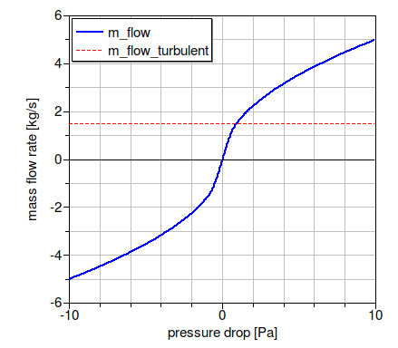
The figure below shows the pressure drop for the parameters
m_flow_nominal=5 kg/s,
dp_nominal=10 Pa and
deltaM=0.3.
Important parameters
The parameter from_dp is used to determine
whether the mass flow rate is computed as a function of the
pressure drop (if from_dp=true), or vice versa.
This setting can affect the size of the nonlinear system of equations.
If the parameter linearized is set to true,
then the pressure drop is computed as a linear function of the
mass flow rate.
To disable any pressure drop calculation, set dp_nominal = 0.
Setting allowFlowReversal=false can lead to simpler
equations. However, this should only be set to false
if one can guarantee that the flow never reverses its direction.
This can be difficult to guarantee, as pressure imbalance after
the initialization, or due to medium expansion and contraction,
can lead to reverse flow.
If the parameter
show_T is set to true,
then the model will compute the
temperature at its ports. Note that this can lead to state events
when the mass flow rate approaches zero,
which can increase computing time.
Notes
For more detailed models that compute the actual flow friction,
models from the package
Modelica.Fluid
can be used and combined with models from the
Buildings library.
For a model that uses the hydraulic parameter and flow velocity at nominal conditions as a parameter, use Buildings.Fluid.FixedResistances.HydraulicDiameter.
Implementation
The pressure drop is computed by calling a function in the package Buildings.Fluid.BaseClasses.FlowModels, This package contains regularized implementations of the equation
ṁ = sign(Δp) k √ Δp
and its inverse function.
To decouple the energy equation from the mass equations, the pressure drop is a function of the mass flow rate, and not the volume flow rate. This leads to simpler equations.
Extends from Buildings.Fluid.BaseClasses.PartialResistance (Partial model for a hydraulic resistance).
Parameters
| Type | Name | Default | Description |
|---|---|---|---|
| replaceable package Medium | PartialMedium | Medium in the component | |
| MassFlowRate | m_flow_turbulent | if computeFlowResistance the... | Turbulent flow if |m_flow| >= m_flow_turbulent [kg/s] |
| Nominal condition | |||
| MassFlowRate | m_flow_nominal | Nominal mass flow rate [kg/s] | |
| PressureDifference | dp_nominal | Pressure drop at nominal mass flow rate [Pa] | |
| Transition to laminar | |||
| Real | deltaM | 0.3 | Fraction of nominal mass flow rate where transition to turbulent occurs |
| Assumptions | |||
| Boolean | allowFlowReversal | true | = false to simplify equations, assuming, but not enforcing, no flow reversal |
| Advanced | |||
| Boolean | from_dp | false | = true, use m_flow = f(dp) else dp = f(m_flow) |
| Boolean | linearized | false | = true, use linear relation between m_flow and dp for any flow rate |
| Diagnostics | |||
| Boolean | show_T | false | = true, if actual temperature at port is computed |
Connectors
| Type | Name | Description |
|---|---|---|
| FluidPort_a | port_a | Fluid connector a (positive design flow direction is from port_a to port_b) |
| FluidPort_b | port_b | Fluid connector b (positive design flow direction is from port_a to port_b) |