Buildings.Fluid.HydronicConfigurations.UsersGuide
User's Guide
Information
This package contains standard configurations used in hydronic circuits, either for heating or cooling applications. They have been selected based mainly on the publications from Petitjean (1994) and HERZ® (2015).
References
HERZ®, 2015. Hydraulics in HVAC applications. HERZ® Armaturen GmbH.
Petitjean, R., 1994. Total hydronic balancing. Tour & Andersson AB, Ljung, Sweden.
Extends from Modelica.Icons.Information (Icon for general information packages).
Package Content
| Name | Description |
|---|---|
| Overview of the configuration models | |
| Description of the model parameters | |
| About control valves | |
| Nomenclature and symbols |
 Buildings.Fluid.HydronicConfigurations.UsersGuide.Overview
Overview of the configuration models
Information
The configurations are grouped together depending on the type of primary network they are compatible with. See Buildings.Fluid.HydronicConfigurations.UsersGuide.NomenclatureSymbols for the definitions of the different circuit types and the symbols used in the schematics below.
Example models using the configurations are provided in Buildings.Fluid.HydronicConfigurations.ActiveNetworks.Examples and Buildings.Fluid.HydronicConfigurations.PassiveNetworks.Examples. It is recommended that the user read the documentation of each example model carefully to understand their implementation, demonstration intent, and observations.
Configurations for active networks
The following table presents the configurations compatible with such networks.
| Designation | Schematic | Application |
|---|---|---|
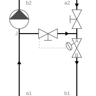
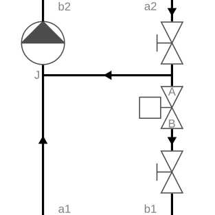
| Decoupling circuit with self-acting Δp control valve |
|
Used for variable flow
primary and consumer circuits where the
consumer circuit has the same supply temperature set point as the
primary circuit.
The fixed bypass prevents the primary pressure differential from being
transmitted to the consumer circuit.
This allows a proper operation of the terminal
control valves when the primary pressure differential is either
too low or too high or varying too much.
The self-acting Δp control valve maintains a nearly constant
bypass mass flow rate. See Buildings.Fluid.HydronicConfigurations.ActiveNetworks.Decoupling for further details. |
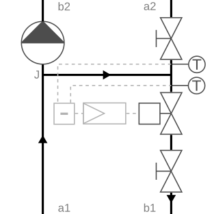
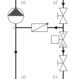
| Decoupling circuit with ΔT control |
|
This configuration is nearly similar to Buildings.Fluid.HydronicConfigurations.ActiveNetworks.Decoupling except that an actuated control valve is used to control the ΔT between the secondary and primary return, ensuring a nearly constant fraction of flow recirculation in the bypass line. This configuration is not included in the package, see the example Buildings.Fluid.HydronicConfigurations.ActiveNetworks.Examples.DecouplingTemperature for a justification. |
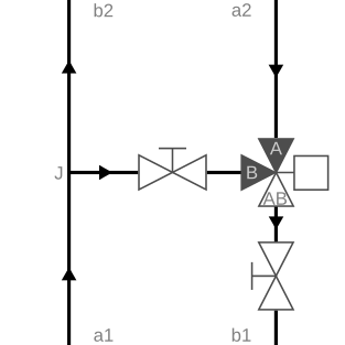
| Diversion circuit |
|
Used for constant flow
primary circuits and variable flow consumer circuits where the
consumer circuit has the same supply temperature set point as the
primary circuit. See Buildings.Fluid.HydronicConfigurations.ActiveNetworks.Diversion for further details. |
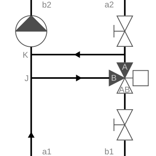
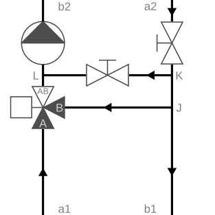
| Injection circuit with three-way valve |
|
Used for constant flow primary and consumer circuits where the
consumer circuit has a different supply temperature set point,
either at design conditions or varying during operation.
Although this configuration may theoretically still be used
if the primary and secondary design temperatures are equal,
it loses its main advantage which is that the
control valve can be sized for a lower flow rate and can therefore
be smaller.
The fixed bypass ensures a consumer circuit operation hydronically decoupled
from the primary side and the control valve position. See Buildings.Fluid.HydronicConfigurations.ActiveNetworks.InjectionThreeWay for further details. |
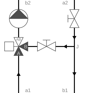
| Injection circuit with two-way valve |
|
Used for variable flow primary circuits and either constant flow or variable
flow consumer circuits.
The fixed bypass prevents the primary pressure differential from being
transmitted to the consumer circuit.
This allows a proper operation of the terminal control valves on the consumer
side when the primary pressure differential is either too low or too high or varying too much. See Buildings.Fluid.HydronicConfigurations.ActiveNetworks.InjectionTwoWay for further details. |
| Injection circuit with two-way valve and check valve in bypass branch |
|
This configuration is nearly similar to
Buildings.Fluid.HydronicConfigurations.ActiveNetworks.InjectionTwoWay
except for the check valve that is added into the bypass.
If used in DHC systems and if the control valve is not properly sized
to maintain the set point at all loads, the check valve prevents recirculation
in the service line which degrades the ΔT in the distribution system.
If used to connect a heating coil, the check valve reduces the risk
of freezing in case of secondary pump failure. See Buildings.Fluid.HydronicConfigurations.ActiveNetworks.InjectionTwoWayCheckValve for further details. |
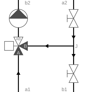
| Single mixing circuit |
|
Used for variable flow primary circuits and
either constant flow or variable flow secondary circuits that
have a design supply temperature identical to the primary circuit
but a varying set point during operation.
The control valve should be sized with a pressure drop equal
to the primary pressure differential.
That pressure drop must be compensated for by the secondary
pump which excludes the use of this configuration to
applications with a high primary pressure differential. See Buildings.Fluid.HydronicConfigurations.ActiveNetworks.SingleMixing for further details. |
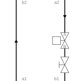
| Throttle circuit |
|
Used for variable flow primary and consumer circuits that have the same supply
temperature set point. See Buildings.Fluid.HydronicConfigurations.ActiveNetworks.Throttle for further details. |
Configurations for passive networks
The following table presents the configurations compatible with such networks.
| Designation | Schematic | Application |
|---|---|---|
| Dual mixing circuit |
|
Used instead of
Buildings.Fluid.HydronicConfigurations.PassiveNetworks.SingleMixing
when the primary and secondary circuits have a different design supply temperature.
Contrary to the single mixing circuit,
the use of this configuration is restricted to constant flow secondary circuits
due to the constraint on the fixed bypass pressure differential that must remain sufficiently
high. See Buildings.Fluid.HydronicConfigurations.PassiveNetworks.DualMixing for further details. |
| Single mixing circuit |
|
Used for variable flow primary circuits and
either constant flow or variable flow secondary circuits that
have a design supply temperature identical to the primary circuit
but a varying set point during operation. See Buildings.Fluid.HydronicConfigurations.PassiveNetworks.SingleMixing for further details. |
Extends from Modelica.Icons.Information (Icon for general information packages).
Modelica definition
Buildings.Fluid.HydronicConfigurations.UsersGuide.ModelParameters
Description of the model parameters
Information
Control valve
The characteristic of the control valve can be selected
using the parameter typCha.
The different choices are defined by the enumeration
Buildings.Fluid.HydronicConfigurations.Types.ValveCharacteristic.
Each model includes an automatic sizing of the control valve based on the considerations provided in the model documentation and considering the two following criteria.
- Valve authority of 0.5.
- Valve design pressure drop higher than 3 kPa, which is considered the limit above which the valve characteristic is valid.
The sizing of the control valve may be disabled by setting the
parameter use_siz to false.
When disabled, the user must assign a value to dpValve_nominal.
When enabled, the user must assign a value to dp1_nominal
and/or dp2_nominal depending on the configuration,
respectively the pressure differential on the primary side and the pressure
drop of the consumer circuit at design conditions.
Note that the sizing rules do not take into account the discrete sizes of control valves. Those are available with Kvs values which increase in a geometric progression, referred to as a Renard series (Petitjean, 1994): Kvs ∈ {1.0, 1.6, 2.5, 4.0, 6.3, 10.0, 16.0, ...}. The models from this package do not take into account those discrete sizes but rather consider that any pressure drop can be achieved at design conditions. Also, the models neither take into account the additional pressure drop of the reducers that are needed when the valve diameter is lower than the pipe diameter.
Distribution pump
For configurations with a secondary distribution pump, the user may choose
whether to include the pump in the configuration model or not, using
the parameter typPum from the enumeration
Buildings.Fluid.HydronicConfigurations.Types.Pump.
When included, the user can further select the type of pump using
the same parameter.
Additionally, the user can select the type of pump model with the
parameter typPumMod from the enumeration
Buildings.Fluid.HydronicConfigurations.Types.PumpModel.
Each model includes an automatic sizing of the optional distribution pump.
By default the secondary pump is parameterized at maximum speed with
m2_flow_nominal and dp2_nominal plus
any additional pressure drop within the hydronic configuration.
The sizing of the pump may be disabled by setting the
parameter use_siz to false.
When disabled, the user must assign a value to mPum_flow_nominal
and dpPum_nominal,
respectively the mass flow rate and total pressure rise at design conditions.
When enabled, the user must assign a value to dp1_nominal
and/or dp2_nominal depending on the configuration,
respectively the pressure differential on the primary side and the pressure
drop of the consumer circuit at design conditions.
A default pump characteristic is also provided, which goes through the design operating point and spans over 0 and twice the design flow rate at maximum speed. This default characteristic is based on a least squares polynomial fit of the characteristics from Buildings.Fluid.Movers.Data.Pumps.Wilo, see Figure 1.
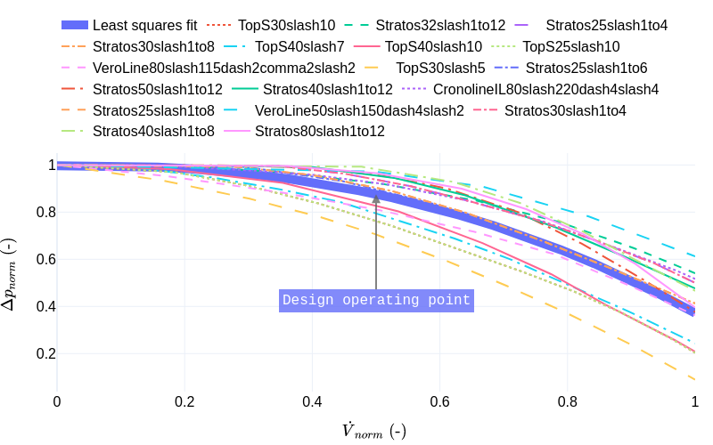
Figure 1. Pump normalized characteristics and least squares polynomial fit.
Balancing valves
The balancing valves are configured with zero pressure drop by default. The user may refer to the documentation of each configuration model for the specific balancing requirements, and assign the proper values to the corresponding parameters.
-
Primary side balancing valve design pressure drop:
dpBal1_nominal -
Consumer circuit balancing valve design pressure drop:
dpBal2_nominal -
Bypass balancing valve design pressure drop:
dpBal3_nominal
References
Petitjean, R., 1994. Total hydronic balancing. Tour & Andersson AB, Ljung, Sweden.
Extends from Modelica.Icons.Information (Icon for general information packages).
Modelica definition
Buildings.Fluid.HydronicConfigurations.UsersGuide.ControlValves
About control valves
Information
Two-way valves
Valve authority (conventional definition)
To define the concept of the valve authority one may start with a reminder of the definition of the valve flow characteristic. The valve flow characteristic is the function that relates the volume flow rate (expressed as the ratio to the flow rate at fully open conditions) to the valve opening for a constant pressure differential: 1 bar in SI units and 1 psi in IP units (refer to Modelica.Fluid.UsersGuide.ComponentDefinition.ValveCharacteristics for further details). However, in a real system the pressure differential at the valve boundaries increases as the valve closes. Indeed, the pressure drop across the other fixed flow resistances in series with the valve (for instance a heat exchanger) tends towards zero with the decreasing flow rate. So the pressure differential available at the circuit boundaries shifts entirely towards the valve. This yields a shift of the "inherent" characteristic of the valve towards higher pressure drop values, hence higher flow rate values. With respect to the control loop this means an increased process gain which may be detrimental to the control loop stability.
The valve authority β is introduced as a metric of this disturbance of the inherent valve characteristic when the valve is integrated into a hydronic circuit. See Buildings.Fluid.HydronicConfigurations.Examples.TwoWayOpenLoop for a numerical illustration. The authority is defined as the ratio between the pressure differential at the valve boundaries when the valve is fully open and the pressure differential at the valve boundaries when the valve is fully closed.
β = Δp(y=100%) / Δp(y=0%)
The above equation is directly tractable in a numerical model and can effectively be used to compute the valve authority.
As mentioned previously, Δp(y=0%) may also be apprehended as the pressure differential at the boundaries of the circuit where the flow rate is modulated by the control valve.
A general design rule for stable controls of hydronic systems is to ensure a control valve authority greater or equal to 0.5.
Practical valve authority
Some authors such as R. Petitjean (1994) claim that the valve authority should be corrected to account for flow imbalance in real systems. Indeed, even for a perfectly balanced system at design conditions, some level of flow imbalance is inevitable at other operating points. Some circuits may therefore be exposed to a pressure differential higher than at design conditions. Such high pressure differential affects Δpmin = Δp(y=100%) and Δpmax = Δp(y=0%) with the same factor. Therefore, the valve authority β remains the same. However, the rate of change of the flow rate with respect to the valve opening is increased and the controllability is potentially degraded, which is not captured by the conventional definition of the authority. The concept of "practical authority" is introduced to overcome that limitation. It is defined as the ratio of the pressure differential at fully open conditions and at design flow rate to the maximum pressure differential corresponding to fully closed conditions.
β' = (Δp valve fully open and design flow) / (Δp valve fully closed)
The two definitions of the authority are related by the square of the ratio of the actual flow rate to the design flow rate.
β' = β / (V̇actual / V̇design)2
Particularly, when the valve is fully open, if the flow rate is equal to the design value then β' = β. In most of the simulation models developed during the design phase, we use theoretical values of pressure drops and consider perfectly balanced systems at design conditions. We will therefore use the conventional authority β for our analysis.
Three-way valves
Three-way valves are typically designed to perform a mixing function, i.e., with two inlet ports and one outlet port. Therefore, all configurations that include three-way valves integrate them in a mixing arrangement, even when they perfom a diverting function such as Buildings.Fluid.HydronicConfigurations.ActiveNetworks.Diversion.
Three-way valve authority
The definition of the authority for a three-way valve is based on the equivalence with a pair of two-way valves actuated in opposition, as illustrated in the figure below.
Using the nomenclature from the right-hand side figure with the pair of two-way valves, we have: β = ΔpA-B(y=100%) / ΔpA-B(y=0%).
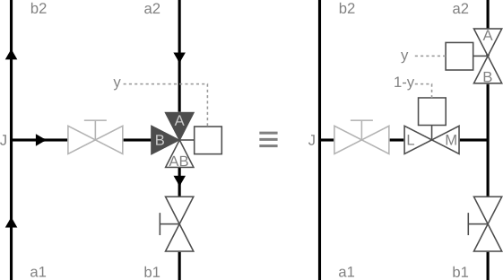
The same caveat as in the case of two-way valves holds for the flow rate at which the pressure drop ΔpA-B(y=100%) is evaluated. There is some additional intricacy for evaluating ΔpA-B(y=0%) = ΔpJ-M(y=0%) because that pressure drop depends on the flow rate in the bypass branch. If the bypass branch is not balanced, the authority given by the above formula can virtually take any value and is no more representative of the valve installed characteristic. Contrary to the pressure drop ΔpA-B(y=100%) that can be corrected to account for a given amount of overflow (see the definition of the practical authority) there is no straightforward correction term that can be formulated for the pressure drop ΔpA-B(y=0%). So, contrary to the case of two-way valves, there is no generic formulation directly tractable in a simulation model to compute the authority of a three-way valve. The above equation requires to "conceptually" consider a balanced bypass when assessing ΔpA-B(y=0%).
For the common case where the valve is used to modulate the flow rate through a coil with a design pressure drop Δpcoil the generic definition of the authority can be rewritten as β = ΔpA-AB(y=100%) / (ΔpA-AB(y=100%) + Δpcoil).
Should the bypass be balanced?
Although this seems as a sound requirement to ensure an actual constant flow with a constant speed pump, the answer actually depends on the application.
- Not recommended: In the case where the valve is used in a mixing configuration with an active primary pressure differential the bypass should not be balanced, see Buildings.Fluid.HydronicConfigurations.ActiveNetworks.SingleMixing.
- Not needed in most cases: In the case where the valve is used in a diversion configuration a balanced bypass is not needed in most cases as long as the valve is selected with a sufficient authority (≥ 0.5) and that the design pressure drop of the served consumer does not represent a significant fraction of the design pump head (≤ 40%). Moreover, a balanced bypass disturbs the linearity of the heat flow rate variation with the valve opening at low load for an equal percentage and linear valve characteristic, see Buildings.Fluid.HydronicConfigurations.ActiveNetworks.Examples.DiversionOpenLoop. Another case where a balanced bypass may be needed is for a mixing circuit connected to a primary passive network. The balancing valve helps countering any significant back pressure from other consumer circuits that could lead to a flow reversal in the primary branch. The example Buildings.Fluid.HydronicConfigurations.PassiveNetworks.Examples.SingleMixingOpenLoop exhibits that phenomenon. However, the example also shows that if the control valve is selected with a sufficient authority (and the secondary pump sized with sufficient head) the risk of flow reversal is avoided.
Default model parameter
The models
Buildings.Fluid.Actuators.Valves.ThreeWayEqualPercentageLinear
and
Buildings.Fluid.Actuators.Valves.ThreeWayLinear
both use a default value of fraK=0.7 for the ratio of
the Kvs coefficient between the bypass branch and the
direct branch.
This default setting yields a pressure drop in the
bypass branch ΔpL-M(y=0%) that is
1 / 0.72 ≈ 2 times higher at design flow rate
than the pressure drop in the
direct branch ΔpA-B(y=100%).
If the valve is used in a diversion arrangement to modulate the flow
rate through a heat exchanger, and if the valve is
sized with an authority of β = 0.5
this default setting implies that the bypass is balanced.
However,
- the corresponding flow resistance is variable (with the valve opening) as opposed to the fixed flow resistance provided by a balancing valve,
-
when trying to match results published by valve manufacturers such as
in Petitjean (1996), the setting
fraK=1.0appears more consistent, -
when used in a different configuration (such as
Buildings.Fluid.HydronicConfigurations.ActiveNetworks.Examples.SingleMixing)
the setting
fraK=0.7may cause sizing issues.
For those reasons the default setting for all three-way valve components
within this package is fraK=1.0 unless specified otherwise.
References
Petitjean, R., 1994. Total hydronic balancing. Tour & Andersson AB, Ljung, Sweden.
Extends from Modelica.Icons.Information (Icon for general information packages).
Modelica definition
Buildings.Fluid.HydronicConfigurations.UsersGuide.NomenclatureSymbols
Nomenclature and symbols
Information
Nomenclature
Active network
An active network is defined as a network where the pressure differential at the boundaries of each connected consumer circuit is primarily driven by the primary circuit circulating pump.
The primary circuit is necessarily equipped with a circulating pump. The connected consumer circuits may be equipped with a circulating pump or not.
Passive network
A passive network is defined as a network where the pressure differential at the boundaries of each connected consumer circuit is primarily driven by the consumer circuit circulating pump.
The connected consumer circuits are necessarily equipped with a circulating pump. However, the primary circuit may be equipped with a circulating pump or not. In the former case, a decoupling device (such as a fixed bypass, a hydraulic separator, or a supply-through loop) is used to cancel out the pressure differential created by the primary pump.
Primary circuit
The word "primary" is used to refer to the source-side circuit which distributes heat or cold and connects with the central plant.
Note that if the central plant already uses a primary-secondary arrangement, then what is called the "primary" circuit is this package is actually the "secondary circuit".
Secondary (consumer) circuit
The word "secondary" or "consumer" is used to refer to the load-side circuit that integrates the terminal units.
Note that if the central plant already uses a primary-secondary arrangement, then what is called the "secondary" circuit is this package is actually the "tertiary circuit".
Symbols
| Symbol | Description |
|---|---|
 |
Balancing valve |
 |
Check valve (the arrow indicating the flow direction is not part of the symbol) |
 |
Circulating pump |
 |
Consumer circuit (typically a heating or cooling circuit or a terminal unit) |
 |
Controller (the dotted lines represent the wiring to the sensor and actuator) |
 |
Self-acting Δp control valve (the dotted lines represent the capillary pipes for pressure measurement) |
 |
Three-way valve with modulating actuator (the arrow indicating the flow direction is not part of the symbol) |
 |
Two-way valve with modulating actuator |
Extends from Modelica.Icons.Information (Icon for general information packages).