Buildings.Fluid.HydronicConfigurations.PassiveNetworks
Package of hydronic configurations for passive networks
Information
This package contains models of hydronic configurations compatible with passive primary networks.
Extends from Modelica.Icons.VariantsPackage (Icon for package containing variants).
Package Content
| Name | Description |
|---|---|
| Dual mixing circuit | |
| Single mixing circuit | |
| Example models |
 Buildings.Fluid.HydronicConfigurations.PassiveNetworks.DualMixing
Dual mixing circuit

Information
Summary
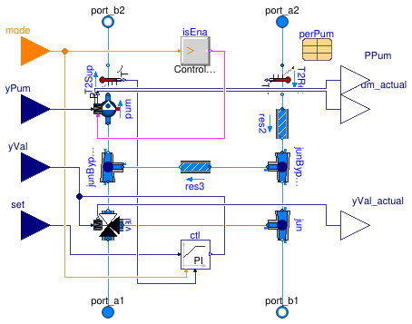
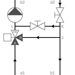
This configuration (see schematic below) is used instead of Buildings.Fluid.HydronicConfigurations.PassiveNetworks.SingleMixing when the primary and secondary circuits have a different design supply temperature. Contrary to the single mixing circuit, the use of this configuration is restricted to constant flow secondary circuits due to the constraint on the fixed bypass pressure differential that must remain sufficiently high.

The following table presents the main characteristics of this configuration.
| Primary circuit | Variable flow |
| Secondary (consumer) circuit | Constant flow |
| Typical applications | Consumer circuit supply temperature different from primary circuit such as underfloor heating systems |
| Non-recommended applications | Applications where primary and secondary supply temperature must be equal as secondary flow recirculation cannot be avoided. |
| Built-in valve control options | Supply temperature |
|
Control valve selection (See the nomenclature in the schematic.) |
β = ΔpA-AB / ΔpK-L =
ΔpA-AB /
(Δp1 + ΔpA-AB) The control valve is sized with a pressure drop equal to the maximum of Δp1 and 3e3 Pa at ṁ1, design (see below). |
| Balancing requirement |
The three-way valve should be fully open at design conditions. |
|
Lumped flow resistance includes (With the setting use_lumFloRes=true.)
|
Control valve val only(So the option has no effect here: the balancing valves are always modeled as distinct flow resistances.) |
Additional comments
The bypass balancing valve works together with the secondary pump to generate the pressure differential differential at the boundaries of the control valve. So it is paramount for proper operation of the consumer circuit that the bypass balancing valve generates enough pressure drop at its design flow rate ṁ3, design otherwise the consumer circuit is starved with primary flow rate despite the control valve being fully open. So oversizing the bypass balancing valve (yielding a lower pressure drop) is detrimental to the consumer circuit operation. Undersizing the bypass balancing valve (yielding a lower pressure drop) does not disturb the secondary circuit operation as the control valve then compensates for the elevated pressure differential by working at a lower opening on average. However, the secondary pump head is increased and so is the electricity consumption. See Buildings.Fluid.HydronicConfigurations.PassiveNetworks.Examples.DualMixing for a numerical illustration of those effects.
The parameter dp1_nominal stands for the potential
primary back pressure and must be provided as an absolute value.
By default the secondary pump is parameterized with a design pressure rise
equal to dp2_nominal + dpBal2_nominal + dpBal3_nominal.
Extends from HydronicConfigurations.Interfaces.PartialHydronicConfiguration.
Parameters
| Type | Name | Default | Description |
|---|---|---|---|
| replaceable package Medium | Water | Medium in the component | |
| Configuration | |||
| Boolean | use_siz | true | Set to true for built-in sizing of control valve and optional pump |
| Boolean | use_dp1 | use_siz | Set to true to enable dp1_nominal |
| Boolean | use_dp2 | use_siz and typPum <> Buildi... | Set to true to enable dp2_nominal |
| Valve | typVal | Buildings.Fluid.HydronicConf... | Type of control valve |
| Boolean | have_typVar | false | Set to true to enable the choice of the controlled variable |
| Nominal condition | |||
| MassFlowRate | m1_flow_nominal | Mass flow rate in primary circuit at design conditions [kg/s] | |
| MassFlowRate | m2_flow_nominal | Mass flow rate in consumer circuit at design conditions [kg/s] | |
| PressureDifference | dp1_nominal | Primary circuit pressure differential at design conditions [Pa] | |
| PressureDifference | dp2_nominal | Consumer circuit pressure differential at design conditions [Pa] | |
| Control valve | |||
| ValveCharacteristic | typCha | Buildings.Fluid.HydronicConf... | Control valve characteristic |
| PressureDifference | dpValve_nominal | max(dp1_nominal, 3e3) | Control valve pressure drop at design conditions [Pa] |
| Generic | flowCharacteristics | Table with flow characteristics | |
| Generic | flowCharacteristics1 | Table with flow characteristics for direct flow path at port_1 | |
| Generic | flowCharacteristics3 | Table with flow characteristics for bypass flow path at port_3 | |
| Pump | |||
| Pump | typPum | Buildings.Fluid.HydronicConf... | Type of secondary pump |
| PumpModel | typPumMod | Buildings.Fluid.HydronicConf... | Type of pump model |
| MassFlowRate | mPum_flow_nominal | m2_flow_nominal | Pump head at design conditions [kg/s] |
| PressureDifference | dpPum_nominal | dp2_nominal + dpBal2_nominal... | Pump head at design conditions [Pa] |
| Generic | perPum | redeclare parameter Movers.D... | Pump parameters |
| Controls | |||
| Control | typCtl | Buildings.Fluid.HydronicConf... | Type of built-in controls |
| ControlVariable | typVar | Buildings.Fluid.HydronicConf... | Controlled variable |
| SimpleController | controllerType | Buildings.Controls.OBC.CDL.T... | Type of controller |
| Real | k | 0.1 | Gain of controller |
| Real | Ti | 120 | Time constant of integrator block [s] |
| Balancing valves | |||
| PressureDifference | dpBal1_nominal | 0 | Primary balancing valve pressure drop at design conditions [Pa] |
| PressureDifference | dpBal2_nominal | 0 | Secondary balancing valve pressure drop at design conditions [Pa] |
| PressureDifference | dpBal3_nominal | dp1_nominal + dpValve_nominal | Bypass balancing valve pressure drop at design conditions [Pa] |
| Assumptions | |||
| Boolean | use_lumFloRes | true | Set to true to use a lumped flow resistance when possible |
| Boolean | allowFlowReversal | true | = false to simplify equations, assuming, but not enforcing, no flow reversal for medium 1 |
| Dynamics | |||
| Conservation equations | |||
| Dynamics | energyDynamics | Modelica.Fluid.Types.Dynamic... | Type of energy balance: dynamic (3 initialization options) or steady state |
| Advanced | |||
| Diagnostics | |||
| Boolean | show_T | false | = true, if actual temperature at port is computed |
Connectors
| Type | Name | Description |
|---|---|---|
| FluidPort_a | port_a1 | Primary supply port |
| FluidPort_b | port_b1 | Primary return port |
| FluidPort_a | port_a2 | Secondary return port |
| FluidPort_b | port_b2 | Secondary supply port |
| input RealInput | yVal | Valve control signal [1] |
| input RealInput | set | Set point [K] |
| input RealInput | yPum | Pump control signal (variable speed) [1] |
| input IntegerInput | mode | Operating mode |
| output RealOutput | yVal_actual | Valve position feedback [1] |
| output RealOutput | yPum_actual | Actual pump input value that is used for computations [1] |
| output RealOutput | PPum | Pump electrical power [W] |
Modelica definition
 Buildings.Fluid.HydronicConfigurations.PassiveNetworks.SingleMixing
Single mixing circuit

Information
Summary
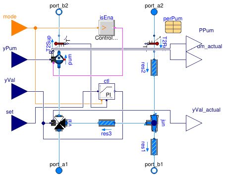
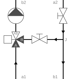
This configuration (see schematic below) is used for variable flow primary circuits and either constant flow or variable flow secondary circuits that have a design supply temperature identical to the primary circuit but a varying set point during operation.

The following table presents the main characteristics of this configuration.
| Primary circuit | Variable flow |
| Secondary (consumer) circuit | Constant or variable flow |
| Typical applications | Widely used in heating applications as it is very simple to achieve. |
| Non-recommended applications | Low-temperature systems that would require the control valve to be operated on a limited opening range: use Buildings.Fluid.HydronicConfigurations.PassiveNetworks.DualMixing instead. |
| Built-in valve control options | Supply temperature |
|
Control valve selection (See the nomenclature in the schematic.) |
β = ΔpA-AB /
(Δp1 + ΔpA-AB) The control valve is sized with a pressure drop equal to the maximum of Δp1 and 3e3 Pa. |
| Balancing requirement | In most cases the bypass balancing valve is not needed. However, it may be needed to counter negative back pressure created by other served circuits, see Buildings.Fluid.HydronicConfigurations.PassiveNetworks.Examples.SingleMixingOpenLoop. |
|
Lumped flow resistance includes (With the setting use_lumFloRes=true.)
|
Control valve val and primary balancing valve res1
|
Additional comments
The parameter dp1_nominal stands for the potential
primary back pressure and must be provided as an absolute value.
By default the secondary pump is parameterized with
a design pressure rise equal to
dp2_nominal + dpBal2_nominal +
max({val.dpValve_nominal + dp1_nominal, val.dp3Valve_nominal + dpBal3_nominal}
.
Extends from BaseClasses.SingleMixing (Single mixing circuit).
Parameters
| Type | Name | Default | Description |
|---|---|---|---|
| replaceable package Medium | Water | Medium in the component | |
| Configuration | |||
| Boolean | use_siz | true | Set to true for built-in sizing of control valve and optional pump |
| Nominal condition | |||
| MassFlowRate | m2_flow_nominal | Mass flow rate in consumer circuit at design conditions [kg/s] | |
| PressureDifference | dp1_nominal | Primary circuit pressure differential at design conditions [Pa] | |
| PressureDifference | dp2_nominal | Consumer circuit pressure differential at design conditions [Pa] | |
| Control valve | |||
| ValveCharacteristic | typCha | Buildings.Fluid.HydronicConf... | Control valve characteristic |
| PressureDifference | dpValve_nominal | max(dp1_nominal, 3E3) | Control valve pressure drop at design conditions [Pa] |
| Generic | flowCharacteristics | Table with flow characteristics | |
| Generic | flowCharacteristics1 | Table with flow characteristics for direct flow path at port_1 | |
| Generic | flowCharacteristics3 | Table with flow characteristics for bypass flow path at port_3 | |
| Pump | |||
| Pump | typPum | Buildings.Fluid.HydronicConf... | Type of secondary pump |
| PumpModel | typPumMod | Buildings.Fluid.HydronicConf... | Type of pump model |
| MassFlowRate | mPum_flow_nominal | m2_flow_nominal | Pump head at design conditions [kg/s] |
| PressureDifference | dpPum_nominal | dp2_nominal + dpBal2_nominal... | Pump head at design conditions [Pa] |
| Generic | perPum | redeclare parameter Movers.D... | Pump parameters |
| Controls | |||
| Control | typCtl | Buildings.Fluid.HydronicConf... | Type of built-in controls |
| ControlVariable | typVar | Buildings.Fluid.HydronicConf... | Controlled variable |
| SimpleController | controllerType | Buildings.Controls.OBC.CDL.T... | Type of controller |
| Real | k | 0.1 | Gain of controller |
| Real | Ti | 120 | Time constant of integrator block [s] |
| Balancing valves | |||
| PressureDifference | dpBal1_nominal | 0 | Primary balancing valve pressure drop at design conditions [Pa] |
| PressureDifference | dpBal2_nominal | 0 | Secondary balancing valve pressure drop at design conditions [Pa] |
| PressureDifference | dpBal3_nominal | 0 | Bypass balancing valve pressure drop at design conditions [Pa] |
| Assumptions | |||
| Boolean | use_lumFloRes | true | Set to true to use a lumped flow resistance when possible |
| Boolean | allowFlowReversal | true | = false to simplify equations, assuming, but not enforcing, no flow reversal for medium 1 |
| Dynamics | |||
| Conservation equations | |||
| Dynamics | energyDynamics | Modelica.Fluid.Types.Dynamic... | Type of energy balance: dynamic (3 initialization options) or steady state |
| Advanced | |||
| Diagnostics | |||
| Boolean | show_T | false | = true, if actual temperature at port is computed |
Connectors
| Type | Name | Description |
|---|---|---|
| FluidPort_a | port_a1 | Primary supply port |
| FluidPort_b | port_b1 | Primary return port |
| FluidPort_a | port_a2 | Secondary return port |
| FluidPort_b | port_b2 | Secondary supply port |
| input RealInput | yVal | Valve control signal [1] |
| input RealInput | set | Set point [K] |
| input RealInput | yPum | Pump control signal (variable speed) [1] |
| input IntegerInput | mode | Operating mode |
| output RealOutput | yVal_actual | Valve position feedback [1] |
| output RealOutput | yPum_actual | Actual pump input value that is used for computations [1] |
| output RealOutput | PPum | Pump electrical power [W] |
