Buildings.Fluid.HydronicConfigurations.ActiveNetworks.Examples.BaseClasses
Package with base classes
Information
This package contains base classes that are used to construct the models in Buildings.Fluid.HydronicConfigurations.ActiveNetworks.Examples.
Extends from Modelica.Icons.BasesPackage (Icon for packages containing base classes).
Package Content
| Name | Description |
|---|---|
| Model of a load on a hydronic circuit | |
| Model of a load on hydronic circuit with flow rate modulation by three-way valve | |
| Model of a load on hydronic circuit with flow rate modulation by two-way valve | |
| Partial model of active primary network | |
| Partial model of primary variable circuit serving a decoupling circuit | |
| Partial model of primary variable circuit serving an inversion circuit with two-way valve | |
| Partial model of a load on hydronic circuit with flow rate modulation by control valve |
 Buildings.Fluid.HydronicConfigurations.ActiveNetworks.Examples.BaseClasses.Load
Model of a load on a hydronic circuit
Information
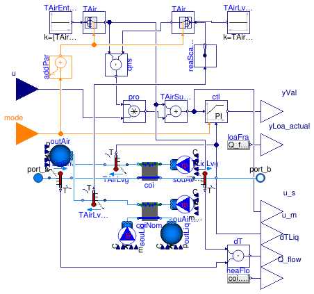
This model represents a thermal load on a hydronic circuit,
typically a terminal unit with recirculating air such as
a fan coil unit.
It takes the fraction of the design load u as input
and returns the control valve demand signal yVal as output.
In steady-state conditions, the model provides zero load
for u=0 and the design load for u=1.
However, for a cooling load with condensation, the relationship between
u and the load is not linear.
The main modeling assumptions are described below.
-
The heat exchanger is modeled in steady-state by default
(dynamics may be reintroduced with the parameter
energyDynamics). -
No pressure drop is considered, neither on the load side, nor
on the source side
(the design pressure drop on the source side may be
reset with the parameter
dpLiq_nominal). - The mass flow rate and the inlet conditions on the load side are constant. The load is modulated by varying the supply temperature set point.
Extends from Buildings.Fluid.Interfaces.PartialTwoPortInterface (Partial model with two ports and declaration of quantities that are used by many models).
Parameters
| Type | Name | Default | Description |
|---|---|---|---|
| replaceable package Medium | PartialMedium | Medium in the component | |
| replaceable package MediumAir | Buildings.Media.Air | Medium model for air | |
| replaceable package MediumLiq | Buildings.Media.Water | Medium model for liquid (CHW or HHW) | |
| Control | typ | Load type | |
| MassFlowRate | mLiq_flow_nominal | 1 | Liquid mass flow rate at design conditions [kg/s] |
| PressureDifference | dpLiq_nominal | 0 | Liquid pressure drop at design conditions [Pa] |
| MassFlowRate | mAir_flow_nominal | abs(Q_flow_nominal)/10/cpAir... | Air mass flow rate at design conditions [kg/s] |
| Temperature | TAirEnt_nominal | if typ == Buildings.Fluid.Hy... | Air entering temperature at design conditions [K] |
| Temperature | TAirEntChg_nominal | 20 + 273.15 | Air entering temperature in change-over mode [K] |
| MassFraction | phiAirEnt_nominal | 0.5 | Air entering relative humidity at design conditions [1] |
| Temperature | TLiqEnt_nominal | if typ == Buildings.Fluid.Hy... | Liquid entering temperature at design conditions [K] |
| Temperature | TLiqLvg_nominal | TLiqEnt_nominal + (if typ ==... | Liquid leaving temperature at design conditions [K] |
| Temperature | TLiqEntChg_nominal | 60 + 273.15 | Liquid entering temperature in change-over mode [K] |
| SimpleController | controllerType | Buildings.Controls.OBC.CDL.T... | Type of controller |
| Nominal condition | |||
| MassFlowRate | m_flow_nominal | mLiq_flow_nominal | Nominal mass flow rate [kg/s] |
| Control gains | |||
| Real | k | 0.1 | Gain of controller |
| Real | Ti | 60 | Time constant of integrator block [s] |
| Assumptions | |||
| Boolean | allowFlowReversal | true | = false to simplify equations, assuming, but not enforcing, no flow reversal |
| Advanced | |||
| MassFlowRate | m_flow_small | 1E-4*abs(m_flow_nominal) | Small mass flow rate for regularization of zero flow [kg/s] |
| Diagnostics | |||
| Boolean | show_T | false | = true, if actual temperature at port is computed |
| Dynamics | |||
| Conservation equations | |||
| Dynamics | energyDynamics | Modelica.Fluid.Types.Dynamic... | Type of energy balance: dynamic (3 initialization options) or steady state |
Connectors
| Type | Name | Description |
|---|---|---|
| replaceable package Medium | Medium in the component | |
| FluidPort_a | port_a | Fluid connector a (positive design flow direction is from port_a to port_b) |
| FluidPort_b | port_b | Fluid connector b (positive design flow direction is from port_a to port_b) |
| replaceable package MediumAir | Medium model for air | |
| replaceable package MediumLiq | Medium model for liquid (CHW or HHW) | |
| input RealInput | u | Load modulating signal |
| input IntegerInput | mode | Operating mode |
| output RealOutput | yVal | Valve demand signal [1] |
| output RealOutput | u_s | Controller set point [K] |
| output RealOutput | u_m | Controller measured value [K] |
| output RealOutput | dTLiq | Liquid deltaT [K] |
| output RealOutput | Q_flow | Total heat flow rate transferred to the load [W] |
| output RealOutput | yLoa_actual | Actual load fraction met [1] |
Modelica definition
 Buildings.Fluid.HydronicConfigurations.ActiveNetworks.Examples.BaseClasses.LoadThreeWayValveControl
Model of a load on hydronic circuit with flow rate modulation by three-way valve
Information
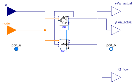
This is a model of a thermal load on a hydronic circuit that is composed of Buildings.Fluid.HydronicConfigurations.ActiveNetworks.Examples.BaseClasses.Load and a diversion circuit with a three-way valve that is used to modulate the flow rate through the load component.
Extends from PartialLoadValveControl (Partial model of a load on hydronic circuit with flow rate modulation by control valve).
Parameters
| Type | Name | Default | Description |
|---|---|---|---|
| replaceable package MediumAir | Air | Medium model for air | |
| replaceable package MediumLiq | Water | Medium model for liquid (CHW or HHW) | |
| Control | typ | Load type | |
| MassFlowRate | mLiq_flow_nominal | 1 | Liquid mass flow rate at design conditions [kg/s] |
| PressureDifference | dpTer_nominal | 3E4 | Liquid pressure drop across terminal unit at design conditions [Pa] |
| MassFlowRate | mAir_flow_nominal | abs(Q_flow_nominal)/10/1015 | Air mass flow rate at design conditions [kg/s] |
| Temperature | TAirEnt_nominal | if typ == Buildings.Fluid.Hy... | Air entering temperature at design conditions [K] |
| Temperature | TAirEntChg_nominal | 20 + 273.15 | Air entering temperature in change-over mode [K] |
| MassFraction | phiAirEnt_nominal | 0.5 | Air entering relative humidity at design conditions [1] |
| Temperature | TLiqEnt_nominal | if typ == Buildings.Fluid.Hy... | Liquid entering temperature at design conditions [K] |
| Temperature | TLiqLvg_nominal | TLiqEnt_nominal + (if typ ==... | Liquid leaving temperature at design conditions [K] |
| Temperature | TLiqEntChg_nominal | 60 + 273.15 | Liquid entering temperature in change-over mode [K] |
| SimpleController | controllerType | Buildings.Controls.OBC.CDL.T... | Type of controller |
| Control valve | |||
| PressureDifference | dpValve_nominal | dpTer_nominal | Control valve pressure drop at design conditions [Pa] |
| Balancing valves | |||
| PressureDifference | dpBal1_nominal | 0 | Balancing valve pressure drop at design conditions [Pa] |
| Control gains | |||
| Real | k | 0.1 | Gain of controller |
| Real | Ti | 60 | Time constant of integrator block [s] |
| Assumptions | |||
| Boolean | allowFlowReversal | true | = false to simplify equations, assuming, but not enforcing, no flow reversal |
| Advanced | |||
| MassFlowRate | m_flow_small | 1E-4*abs(m_flow_nominal) | Small mass flow rate for regularization of zero flow [kg/s] |
| Diagnostics | |||
| Boolean | show_T | false | = true, if actual temperature at port is computed |
| Dynamics | |||
| Conservation equations | |||
| Dynamics | energyDynamics | Modelica.Fluid.Types.Dynamic... | Type of energy balance: dynamic (3 initialization options) or steady state |
Connectors
| Type | Name | Description |
|---|---|---|
| FluidPort_a | port_a | Fluid connector a (positive design flow direction is from port_a to port_b) |
| FluidPort_b | port_b | Fluid connector b (positive design flow direction is from port_a to port_b) |
| input RealInput | u | Load modulating signal |
| input IntegerInput | mode | Operating mode |
| output RealOutput | yLoa_actual | Actual load fraction met [1] |
| output RealOutput | Q_flow | Total heat flow rate transferred to the load [W] |
| output RealOutput | yVal_actual | Valve position feedback [1] |
Modelica definition
 Buildings.Fluid.HydronicConfigurations.ActiveNetworks.Examples.BaseClasses.LoadTwoWayValveControl
Model of a load on hydronic circuit with flow rate modulation by two-way valve
Information
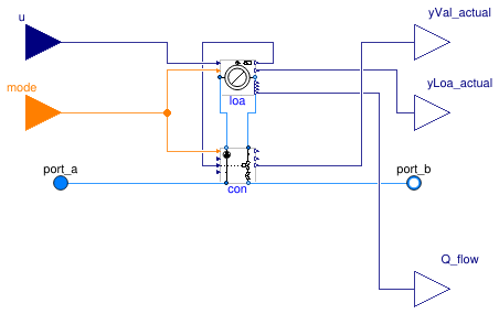
This is a model of a thermal load on a hydronic circuit that is composed of Buildings.Fluid.HydronicConfigurations.ActiveNetworks.Examples.BaseClasses.Load and a throttle circuit with a two-way valve that is used to modulate the flow rate through the load component.
Extends from PartialLoadValveControl (Partial model of a load on hydronic circuit with flow rate modulation by control valve).
Parameters
| Type | Name | Default | Description |
|---|---|---|---|
| replaceable package MediumAir | Air | Medium model for air | |
| replaceable package MediumLiq | Water | Medium model for liquid (CHW or HHW) | |
| Control | typ | Load type | |
| MassFlowRate | mLiq_flow_nominal | 1 | Liquid mass flow rate at design conditions [kg/s] |
| PressureDifference | dpTer_nominal | 3E4 | Liquid pressure drop across terminal unit at design conditions [Pa] |
| MassFlowRate | mAir_flow_nominal | abs(Q_flow_nominal)/10/1015 | Air mass flow rate at design conditions [kg/s] |
| Temperature | TAirEnt_nominal | if typ == Buildings.Fluid.Hy... | Air entering temperature at design conditions [K] |
| Temperature | TAirEntChg_nominal | 20 + 273.15 | Air entering temperature in change-over mode [K] |
| MassFraction | phiAirEnt_nominal | 0.5 | Air entering relative humidity at design conditions [1] |
| Temperature | TLiqEnt_nominal | if typ == Buildings.Fluid.Hy... | Liquid entering temperature at design conditions [K] |
| Temperature | TLiqLvg_nominal | TLiqEnt_nominal + (if typ ==... | Liquid leaving temperature at design conditions [K] |
| Temperature | TLiqEntChg_nominal | 60 + 273.15 | Liquid entering temperature in change-over mode [K] |
| SimpleController | controllerType | Buildings.Controls.OBC.CDL.T... | Type of controller |
| Control valve | |||
| PressureDifference | dpValve_nominal | dpTer_nominal | Control valve pressure drop at design conditions [Pa] |
| Balancing valves | |||
| PressureDifference | dpBal1_nominal | 0 | Balancing valve pressure drop at design conditions [Pa] |
| Control gains | |||
| Real | k | 0.1 | Gain of controller |
| Real | Ti | 60 | Time constant of integrator block [s] |
| Assumptions | |||
| Boolean | allowFlowReversal | true | = false to simplify equations, assuming, but not enforcing, no flow reversal |
| Advanced | |||
| MassFlowRate | m_flow_small | 1E-4*abs(m_flow_nominal) | Small mass flow rate for regularization of zero flow [kg/s] |
| Diagnostics | |||
| Boolean | show_T | false | = true, if actual temperature at port is computed |
| Dynamics | |||
| Conservation equations | |||
| Dynamics | energyDynamics | Modelica.Fluid.Types.Dynamic... | Type of energy balance: dynamic (3 initialization options) or steady state |
Connectors
| Type | Name | Description |
|---|---|---|
| FluidPort_a | port_a | Fluid connector a (positive design flow direction is from port_a to port_b) |
| FluidPort_b | port_b | Fluid connector b (positive design flow direction is from port_a to port_b) |
| input RealInput | u | Load modulating signal |
| input IntegerInput | mode | Operating mode |
| output RealOutput | yLoa_actual | Actual load fraction met [1] |
| output RealOutput | Q_flow | Total heat flow rate transferred to the load [W] |
| output RealOutput | yVal_actual | Valve position feedback [1] |
Modelica definition
 Buildings.Fluid.HydronicConfigurations.ActiveNetworks.Examples.BaseClasses.PartialActivePrimary
Partial model of active primary network
Information
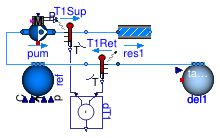
This is a partial model of an active primary network with a replaceable pump model. That model is used to construct the various example models within Buildings.Fluid.HydronicConfigurations.ActiveNetworks.Examples. It can be configured to represent either a heating or a cooling system.
Extends from Modelica.Icons.Example (Icon for runnable examples).
Parameters
| Type | Name | Default | Description |
|---|---|---|---|
| Control | typ | Buildings.Fluid.HydronicConf... | Load type |
| Integer | nTer | 2 | Number of terminal units |
| Real | kSizPum | 1.0 | Pump oversizing coefficient [1] |
| Pressure | p_min | 200000 | Circuit minimum pressure [Pa] |
| Temperature | TLiqEnt_nominal | if typ == Buildings.Fluid.Hy... | Liquid entering temperature at design conditions [K] |
| Temperature | TLiqLvg_nominal | TLiqEnt_nominal + (if typ ==... | Liquid leaving temperature at design conditions [K] |
| Temperature | TLiqEntChg_nominal | 60 + 273.15 | Liquid entering temperature in change-over mode [K] |
| Temperature | TLiqSup_nominal | TLiqEnt_nominal | Liquid primary supply temperature at design conditions [K] |
| Temperature | TLiqSupChg_nominal | TLiqEntChg_nominal | Liquid primary supply temperature in change-over mode [K] |
| Nominal condition | |||
| MassFlowRate | mTer_flow_nominal | 1 | Terminal unit mass flow rate at design conditions [kg/s] |
| MassFlowRate | m1_flow_nominal | m2_flow_nominal | Mass flow rate in primary branch at design conditions [kg/s] |
| MassFlowRate | m2_flow_nominal | nTer*mTer_flow_nominal | Mass flow rate in consumer circuit at design conditions [kg/s] |
| PressureDifference | dpTer_nominal | 3E4 | Terminal unit pressure drop at design conditions [Pa] |
| PressureDifference | dpPip_nominal | 0.5E4 | Pipe section pressure drop at design conditions [Pa] |
| PressureDifference | dpPum_nominal | Pump head at design conditions [Pa] | |
| MassFlowRate | mPum_flow_nominal | m1_flow_nominal | Primary pump mass flow rate at design conditions [kg/s] |
| Dynamics | |||
| Conservation equations | |||
| Dynamics | energyDynamics | Modelica.Fluid.Types.Dynamic... | Type of energy balance: dynamic (3 initialization options) or steady state |
Modelica definition
 Buildings.Fluid.HydronicConfigurations.ActiveNetworks.Examples.BaseClasses.PartialDecoupling
Partial model of primary variable circuit serving a decoupling circuit
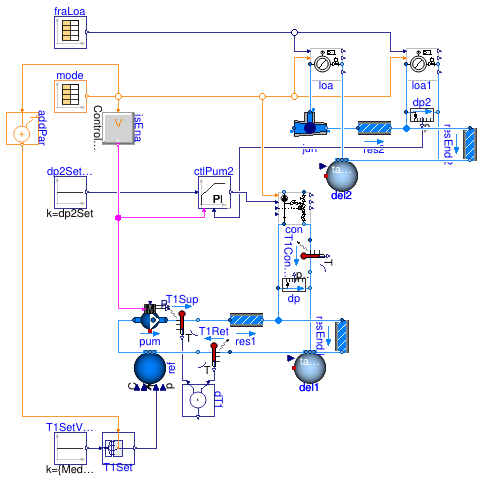
Information
This is a partial model of a change-over system. The variable flow primary loop includes a variable speed pump serving a variable flow decoupling circuit with a variable speed pump and two-way valves. The primary pump model takes an ideally controlled head as input. The secondary pump model takes a normalized speed as input. The pump speed is modulated to track a constant pressure differential at the boundaries of the remote terminal unit.
Two identical terminal units are served by the secondary circuit. Each terminal unit has its own hourly load profile. Each terminal unit is balanced at design conditions.
The design conditions are defined without considering any load diversity.
That model is used to construct some example models within Buildings.Fluid.HydronicConfigurations.ActiveNetworks.Examples.
Extends from BaseClasses.PartialActivePrimary (Partial model of active primary network).
Parameters
| Type | Name | Default | Description |
|---|---|---|---|
| Control | typ | Buildings.Fluid.HydronicConf... | Load type |
| Integer | nTer | 2 | Number of terminal units |
| Real | kSizPum | 1.0 | Pump oversizing coefficient [1] |
| Pressure | p_min | 200000 | Circuit minimum pressure [Pa] |
| Temperature | TLiqEnt_nominal | if typ == Buildings.Fluid.Hy... | Liquid entering temperature at design conditions [K] |
| Temperature | TLiqLvg_nominal | TLiqEnt_nominal + (if typ ==... | Liquid leaving temperature at design conditions [K] |
| Temperature | TLiqEntChg_nominal | 60 + 273.15 | Liquid entering temperature in change-over mode [K] |
| Temperature | TLiqSup_nominal | TLiqEnt_nominal | Liquid primary supply temperature at design conditions [K] |
| Temperature | TLiqSupChg_nominal | TLiqEntChg_nominal | Liquid primary supply temperature in change-over mode [K] |
| PressureDifference | dp1_nominal | dpPum_nominal - dpPip_nominal | Control valve pressure drop at design conditions [Pa] |
| Nominal condition | |||
| MassFlowRate | mTer_flow_nominal | 1 | Terminal unit mass flow rate at design conditions [kg/s] |
| MassFlowRate | m1_flow_nominal | 1.1*m2_flow_nominal | Mass flow rate in primary branch at design conditions [kg/s] |
| MassFlowRate | m2_flow_nominal | nTer*mTer_flow_nominal/0.9 | Mass flow rate in consumer circuit at design conditions [kg/s] |
| PressureDifference | dpTer_nominal | 3E4 | Terminal unit pressure drop at design conditions [Pa] |
| PressureDifference | dpPip_nominal | 0.5E4 | Pipe section pressure drop at design conditions [Pa] |
| PressureDifference | dpPum_nominal | 10e4 | Pump head at design conditions [Pa] |
| MassFlowRate | mPum_flow_nominal | m1_flow_nominal/0.9 | Primary pump mass flow rate at design conditions [kg/s] |
| PressureDifference | dp2_nominal | dpPip_nominal + dp2Set | Consumer circuit pressure differential at design conditions [Pa] |
| Configuration | |||
| Boolean | is_bal | true | Set to true for balanced primary branch |
| Controls | |||
| PressureDifference | dp2Set | loa1.dpTer_nominal + loa1.dp... | Consumer circuit pressure differential set point [Pa] |
| Dynamics | |||
| Conservation equations | |||
| Dynamics | energyDynamics | Modelica.Fluid.Types.Dynamic... | Type of energy balance: dynamic (3 initialization options) or steady state |
Modelica definition
 Buildings.Fluid.HydronicConfigurations.ActiveNetworks.Examples.BaseClasses.PartialInjectionTwoWay
Partial model of primary variable circuit serving an inversion circuit with two-way valve
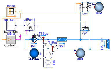
Information
This is a partial model of a variable flow primary loop with a variable speed pump serving an injection circuit with a two-way valve. The primary pump model takes a normalized speed as input. The speed is modulated to track a constant pressure differential at the boundaries of the injection unit. That model is used to construct some example models within Buildings.Fluid.HydronicConfigurations.ActiveNetworks.Examples.
Extends from PartialActivePrimary (Partial model of active primary network).
Parameters
| Type | Name | Default | Description |
|---|---|---|---|
| Control | typ | Buildings.Fluid.HydronicConf... | Load type |
| Integer | nTer | 2 | Number of terminal units |
| Real | kSizPum | 1.0 | Pump oversizing coefficient [1] |
| Pressure | p_min | 200000 | Circuit minimum pressure [Pa] |
| Temperature | TLiqEnt_nominal | 55 + 273.15 | Liquid entering temperature at design conditions [K] |
| Temperature | TLiqLvg_nominal | TLiqEnt_nominal + (if typ ==... | Liquid leaving temperature at design conditions [K] |
| Temperature | TLiqEntChg_nominal | 60 + 273.15 | Liquid entering temperature in change-over mode [K] |
| Temperature | TLiqSup_nominal | 60 + 273.15 | Liquid primary supply temperature at design conditions [K] |
| Temperature | TLiqSupChg_nominal | TLiqEntChg_nominal | Liquid primary supply temperature in change-over mode [K] |
| InjectionTwoWay | con | con(use_lumFloRes=true, typC... | Hydronic connection |
| Nominal condition | |||
| MassFlowRate | mTer_flow_nominal | 1 | Terminal unit mass flow rate at design conditions [kg/s] |
| MassFlowRate | m1_flow_nominal | m2_flow_nominal*(TLiqEnt_nom... | Mass flow rate in primary branch at design conditions [kg/s] |
| MassFlowRate | m2_flow_nominal | nTer*mTer_flow_nominal | Mass flow rate in consumer circuit at design conditions [kg/s] |
| PressureDifference | dpTer_nominal | 3E4 | Terminal unit pressure drop at design conditions [Pa] |
| PressureDifference | dpPip_nominal | 0.5E4 | Pipe section pressure drop at design conditions [Pa] |
| PressureDifference | dpPum_nominal | (dpPip_nominal + dp1Set)*kSi... | Pump head at design conditions [Pa] |
| MassFlowRate | mPum_flow_nominal | m1_flow_nominal/0.9 | Primary pump mass flow rate at design conditions [kg/s] |
| PressureDifference | dp2_nominal | Consumer circuit pressure differential at design conditions [Pa] | |
| Configuration | |||
| Boolean | is_bal | false | Set to true for balanced primary branch |
| Controls | |||
| PressureDifference | dp1Set | 1e4 | Pressure differential set point [Pa] |
| Dynamics | |||
| Conservation equations | |||
| Dynamics | energyDynamics | Modelica.Fluid.Types.Dynamic... | Type of energy balance: dynamic (3 initialization options) or steady state |
Modelica definition
 Buildings.Fluid.HydronicConfigurations.ActiveNetworks.Examples.BaseClasses.PartialLoadValveControl
Partial model of a load on hydronic circuit with flow rate modulation by control valve
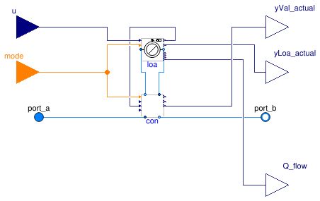
Information
This is a partial model of a thermal load on a hydronic circuit that is composed of Buildings.Fluid.HydronicConfigurations.ActiveNetworks.Examples.BaseClasses.Load and a replaceable configuration component derived from Buildings.Fluid.HydronicConfigurations.Interfaces.PartialHydronicConfiguration that is used to modulate the flow rate through the load component.
Extends from Buildings.Fluid.Interfaces.PartialTwoPortInterface (Partial model with two ports and declaration of quantities that are used by many models).
Parameters
| Type | Name | Default | Description |
|---|---|---|---|
| replaceable package Medium | PartialMedium | Medium in the component | |
| replaceable package MediumAir | Buildings.Media.Air | Medium model for air | |
| replaceable package MediumLiq | Buildings.Media.Water | Medium model for liquid (CHW or HHW) | |
| Control | typ | Load type | |
| MassFlowRate | mLiq_flow_nominal | 1 | Liquid mass flow rate at design conditions [kg/s] |
| PressureDifference | dpTer_nominal | 3E4 | Liquid pressure drop across terminal unit at design conditions [Pa] |
| MassFlowRate | mAir_flow_nominal | abs(Q_flow_nominal)/10/1015 | Air mass flow rate at design conditions [kg/s] |
| Temperature | TAirEnt_nominal | if typ == Buildings.Fluid.Hy... | Air entering temperature at design conditions [K] |
| Temperature | TAirEntChg_nominal | 20 + 273.15 | Air entering temperature in change-over mode [K] |
| MassFraction | phiAirEnt_nominal | 0.5 | Air entering relative humidity at design conditions [1] |
| Temperature | TLiqEnt_nominal | if typ == Buildings.Fluid.Hy... | Liquid entering temperature at design conditions [K] |
| Temperature | TLiqLvg_nominal | TLiqEnt_nominal + (if typ ==... | Liquid leaving temperature at design conditions [K] |
| Temperature | TLiqEntChg_nominal | 60 + 273.15 | Liquid entering temperature in change-over mode [K] |
| SimpleController | controllerType | Buildings.Controls.OBC.CDL.T... | Type of controller |
| PartialHydronicConfiguration | con | redeclare HydronicConfigurat... | Diversion connection |
| Nominal condition | |||
| MassFlowRate | m_flow_nominal | mLiq_flow_nominal | Nominal mass flow rate [kg/s] |
| Control valve | |||
| PressureDifference | dpValve_nominal | dpTer_nominal | Control valve pressure drop at design conditions [Pa] |
| Balancing valves | |||
| PressureDifference | dpBal1_nominal | 0 | Balancing valve pressure drop at design conditions [Pa] |
| Control gains | |||
| Real | k | 0.1 | Gain of controller |
| Real | Ti | 60 | Time constant of integrator block [s] |
| Assumptions | |||
| Boolean | allowFlowReversal | true | = false to simplify equations, assuming, but not enforcing, no flow reversal |
| Advanced | |||
| MassFlowRate | m_flow_small | 1E-4*abs(m_flow_nominal) | Small mass flow rate for regularization of zero flow [kg/s] |
| Diagnostics | |||
| Boolean | show_T | false | = true, if actual temperature at port is computed |
| Dynamics | |||
| Conservation equations | |||
| Dynamics | energyDynamics | Modelica.Fluid.Types.Dynamic... | Type of energy balance: dynamic (3 initialization options) or steady state |
Connectors
| Type | Name | Description |
|---|---|---|
| replaceable package Medium | Medium in the component | |
| FluidPort_a | port_a | Fluid connector a (positive design flow direction is from port_a to port_b) |
| FluidPort_b | port_b | Fluid connector b (positive design flow direction is from port_a to port_b) |
| replaceable package MediumAir | Medium model for air | |
| replaceable package MediumLiq | Medium model for liquid (CHW or HHW) | |
| input RealInput | u | Load modulating signal |
| input IntegerInput | mode | Operating mode |
| output RealOutput | yLoa_actual | Actual load fraction met [1] |
| output RealOutput | Q_flow | Total heat flow rate transferred to the load [W] |
| output RealOutput | yVal_actual | Valve position feedback [1] |
