Buildings.ThermalZones.EnergyPlus_9_6_0.Examples.SmallOffice.BaseClasses

Package with base classes

Information

This package contains base classes that are used to construct the models in Buildings.ThermalZones.EnergyPlus_9_6_0.Examples.SmallOffice.

Extends from Modelica.Icons.BasesPackage (Icon for packages containing base classes).

Package Content

Name Description
Buildings.ThermalZones.EnergyPlus_9_6_0.Examples.SmallOffice.BaseClasses.Floor Floor Model of a floor of the building
Buildings.ThermalZones.EnergyPlus_9_6_0.Examples.SmallOffice.BaseClasses.IdealHeaterCooler IdealHeaterCooler Model of ideal heater or cooler

Buildings.ThermalZones.EnergyPlus_9_6_0.Examples.SmallOffice.BaseClasses.Floor Buildings.ThermalZones.EnergyPlus_9_6_0.Examples.SmallOffice.BaseClasses.Floor

Model of a floor of the building

Buildings.ThermalZones.EnergyPlus_9_6_0.Examples.SmallOffice.BaseClasses.Floor

Information

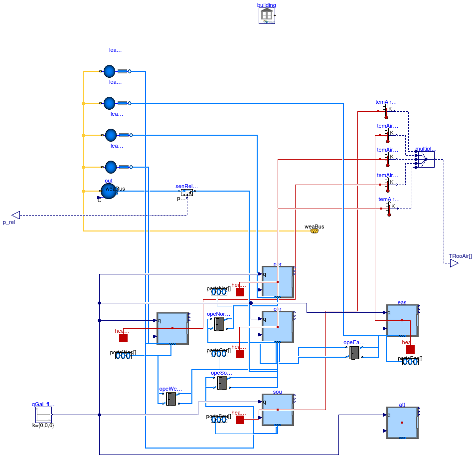
Model of a floor that consists of five thermal zones.

The five room model is representative of one floor of the new construction small office building for Chicago, IL, as described in the set of DOE Commercial Building Benchmarks (Deru et al, 2009). There are four perimeter zones and one core zone. The envelope thermal properties meet ASHRAE Standard 90.1-2004.

Each thermal zone can have air flow from the HVAC system, through leakages of the building envelope (except for the core zone) and through bi-directional air exchange through open doors that connect adjacent zones. The bi-directional air exchange is modeled based on the differences in static pressure between adjacent rooms at a reference height plus the difference in static pressure across the door height as a function of the difference in air density. Infiltration is a function of the flow imbalance of the HVAC system.

Implementation

Compared to the base class, which has been built for the models in Buildings.Examples.VAVReheat which are for a larger building, the instances of Buildings.Airflow.Multizone.DoorOpen are made smaller. Their length has been reduced proportionally to the difference in length of the walls of the core zone of the two buildings. See also Buildings.ThermalZones.EnergyPlus_9_6_0.Examples.SmallOffice for a description of the differences in these buildings.

References

Deru M., K. Field, D. Studer, K. Benne, B. Griffith, P. Torcellini, M. Halverson, D. Winiarski, B. Liu, M. Rosenberg, J. Huang, M. Yazdanian, and D. Crawley. DOE commercial building research benchmarks for commercial buildings. Technical report, U.S. Department of Energy, Energy Efficiency and Renewable Energy, Office of Building Technologies, Washington, DC, 2009.

Extends from Buildings.Examples.VAVReheat.BaseClasses.PartialFloor (Interface for a model of a floor of a building).

Parameters

TypeNameDefaultDescription
replaceable package MediumPartialMediumMedium model for air
Booleanuse_windPressuretrueSet to true to enable wind pressure
RealkIntNor1Gain factor to scale internal heat gain in north zone
VolumeVRooCor456.455Room volume corridor [m3]
VolumeVRooSou346.022Room volume south [m3]
VolumeVRooNor346.022Room volume north [m3]
VolumeVRooEas205.265Room volume east [m3]
VolumeVRooWes205.265Room volume west [m3]
AreaAFloCorcor.AFloFloor area corridor [m2]
AreaAFloSousou.AFloFloor area south [m2]
AreaAFloNornor.AFloFloor area north [m2]
AreaAFloEaseas.AFloFloor area east [m2]
AreaAFloWeswes.AFloFloor area west [m2]
StringidfNameModelica.Utilities.Files.loa...Name of the IDF file
StringepwNameModelica.Utilities.Files.loa...Name of the weather file
StringweaNameModelica.Utilities.Files.loa...Name of the weather file

Connectors

TypeNameDescription
VesselFluidPorts_bportsSou[2]Fluid inlets and outlets
VesselFluidPorts_bportsEas[2]Fluid inlets and outlets
VesselFluidPorts_bportsNor[2]Fluid inlets and outlets
VesselFluidPorts_bportsWes[2]Fluid inlets and outlets
VesselFluidPorts_bportsCor[2]Fluid inlets and outlets
output RealOutputTRooAir[5]Room air temperatures [K]
output RealOutputp_relRelative pressure signal of building static pressure
BusweaBusWeather bus
HeatPort_aheaPorSouHeat port to air volume South
HeatPort_aheaPorEasHeat port to air volume East
HeatPort_aheaPorNorHeat port to air volume North
HeatPort_aheaPorWesHeat port to air volume West
HeatPort_aheaPorCorHeat port to air volume corridor

Modelica definition

model Floor "Model of a floor of the building" extends Buildings.Examples.VAVReheat.BaseClasses.PartialFloor( VRooCor=456.455, VRooSou=346.022, VRooNor=346.022, VRooEas=205.265, VRooWes=205.265, AFloCor=cor.AFlo, AFloSou=sou.AFlo, AFloNor=nor.AFlo, AFloEas=eas.AFlo, AFloWes=wes.AFlo, opeWesCor( wOpe=4), opeSouCor( wOpe=9), opeNorCor( wOpe=9), opeEasCor( wOpe=4), leaWes( s=18.46/27.69), leaSou( s=27.69/18.46), leaNor( s=27.69/18.46), leaEas( s=18.46/27.69)); final parameter Modelica.Units.SI.Area AFlo=AFloCor + AFloSou + AFloNor + AFloEas + AFloWes "Total floor area"; Modelica.Thermal.HeatTransfer.Interfaces.HeatPort_a heaPorSou "Heat port to air volume South"; Modelica.Thermal.HeatTransfer.Interfaces.HeatPort_a heaPorEas "Heat port to air volume East"; Modelica.Thermal.HeatTransfer.Interfaces.HeatPort_a heaPorNor "Heat port to air volume North"; Modelica.Thermal.HeatTransfer.Interfaces.HeatPort_a heaPorWes "Heat port to air volume West"; Modelica.Thermal.HeatTransfer.Interfaces.HeatPort_a heaPorCor "Heat port to air volume corridor"; Modelica.Units.SI.Temperature TAirCor=cor.TAir "Air temperature corridor"; Modelica.Units.SI.Temperature TAirSou=sou.TAir "Air temperature south zone"; Modelica.Units.SI.Temperature TAirNor=nor.TAir "Air temperature north zone"; Modelica.Units.SI.Temperature TAirEas=eas.TAir "Air temperature east zone"; Modelica.Units.SI.Temperature TAirWes=wes.TAir "Air temperature west zone"; Buildings.ThermalZones.EnergyPlus_9_6_0.ThermalZone sou( redeclare package Medium=Medium, nPorts=5, zoneName="Perimeter_ZN_1") "South zone"; Buildings.ThermalZones.EnergyPlus_9_6_0.ThermalZone eas( redeclare package Medium=Medium, nPorts=5, zoneName="Perimeter_ZN_2") "East zone"; Buildings.ThermalZones.EnergyPlus_9_6_0.ThermalZone nor( redeclare package Medium=Medium, nPorts=5, zoneName="Perimeter_ZN_3") "North zone"; Buildings.ThermalZones.EnergyPlus_9_6_0.ThermalZone wes( redeclare package Medium=Medium, nPorts=5, zoneName="Perimeter_ZN_4") "West zone"; Buildings.ThermalZones.EnergyPlus_9_6_0.ThermalZone cor( redeclare package Medium=Medium, nPorts=11, zoneName="Core_ZN") "Core zone"; Buildings.ThermalZones.EnergyPlus_9_6_0.ThermalZone att( redeclare package Medium=Medium, zoneName="Attic", T_start=275.15) "Attic zone"; parameter String idfName=Modelica.Utilities.Files.loadResource( "modelica://Buildings/Resources/Data/ThermalZones/EnergyPlus_9_6_0/Examples/RefBldgSmallOffice/RefBldgSmallOfficeNew2004_Chicago.idf") "Name of the IDF file"; parameter String epwName=Modelica.Utilities.Files.loadResource( "modelica://Buildings/Resources/weatherdata/USA_IL_Chicago-OHare.Intl.AP.725300_TMY3.epw") "Name of the weather file"; parameter String weaName=Modelica.Utilities.Files.loadResource( "modelica://Buildings/Resources/weatherdata/USA_IL_Chicago-OHare.Intl.AP.725300_TMY3.mos") "Name of the weather file"; protected inner Buildings.ThermalZones.EnergyPlus_9_6_0.Building building( idfName=idfName, epwName=epwName, weaName=weaName, computeWetBulbTemperature=false) "Building-level declarations"; Buildings.Controls.OBC.CDL.Continuous.Sources.Constant qGai_flow[3]( k={0,0,0}) "Internal heat gain (computed already in EnergyPlus"; initial equation assert( abs( cor.V-VRooCor) < 0.01, "Volumes don't match. These had to be entered manually to avoid using a non-literal value."); assert( abs( sou.V-VRooSou) < 0.01, "Volumes don't match. These had to be entered manually to avoid using a non-literal value."); assert( abs( nor.V-VRooNor) < 0.01, "Volumes don't match. These had to be entered manually to avoid using a non-literal value."); assert( abs( eas.V-VRooEas) < 0.01, "Volumes don't match. These had to be entered manually to avoid using a non-literal value."); assert( abs( wes.V-VRooWes) < 0.01, "Volumes don't match. These had to be entered manually to avoid using a non-literal value."); // Other models may override the assignment for AFlo. Hence we check below for consistency. assert( abs( cor.AFlo-AFloCor) < 0.01, "Areas don't match. Make sure model that overrides these parameter defaults uses the same values as the idf file uses."); assert( abs( sou.AFlo-AFloSou) < 0.01, "Areas don't match. Make sure model that overrides these parameter defaults uses the same values as the idf file uses."); assert( abs( nor.AFlo-AFloNor) < 0.01, "Areas don't match. Make sure model that overrides these parameter defaults uses the same values as the idf file uses."); assert( abs( eas.AFlo-AFloEas) < 0.01, "Areas don't match. Make sure model that overrides these parameter defaults uses the same values as the idf file uses."); assert( abs( wes.AFlo-AFloWes) < 0.01, "Areas don't match. Make sure model that overrides these parameter defaults uses the same values as the idf file uses."); equation connect(sou.heaPorAir,temAirSou.port); connect(eas.heaPorAir,temAirEas.port); connect(nor.heaPorAir,temAirNor.port); connect(wes.heaPorAir,temAirWes.port); connect(cor.heaPorAir,temAirCor.port); connect(sou.ports[1],portsSou[1]); connect(sou.ports[2],portsSou[2]); connect(eas.ports[1],portsEas[1]); connect(eas.ports[2],portsEas[2]); connect(nor.ports[1],portsNor[1]); connect(nor.ports[2],portsNor[2]); connect(wes.ports[1],portsWes[1]); connect(wes.ports[2],portsWes[2]); connect(cor.ports[1],portsCor[1]); connect(cor.ports[2],portsCor[2]); connect(leaSou.port_b,sou.ports[3]); connect(leaEas.port_b,eas.ports[3]); connect(leaNor.port_b,nor.ports[3]); connect(leaWes.port_b,wes.ports[3]); connect(opeSouCor.port_b1,cor.ports[3]); connect(opeSouCor.port_a2,cor.ports[4]); connect(opeSouCor.port_a1,sou.ports[4]); connect(opeSouCor.port_b2,sou.ports[5]); connect(opeEasCor.port_b1,eas.ports[4]); connect(opeEasCor.port_a2,eas.ports[5]); connect(opeEasCor.port_a1,cor.ports[5]); connect(opeEasCor.port_b2,cor.ports[6]); connect(opeNorCor.port_b1,nor.ports[4]); connect(opeNorCor.port_a2,nor.ports[5]); connect(opeNorCor.port_a1,cor.ports[7]); connect(opeNorCor.port_b2,cor.ports[8]); connect(opeWesCor.port_b1,cor.ports[9]); connect(opeWesCor.port_a2,cor.ports[10]); connect(opeWesCor.port_a1,wes.ports[4]); connect(opeWesCor.port_b2,wes.ports[5]); connect(cor.ports[11],senRelPre.port_a); connect(sou.qGai_flow,qGai_flow.y); connect(wes.qGai_flow,qGai_flow.y); connect(eas.qGai_flow,qGai_flow.y); connect(cor.qGai_flow,qGai_flow.y); connect(nor.qGai_flow,qGai_flow.y); connect(att.qGai_flow,qGai_flow.y); connect(sou.heaPorAir,heaPorSou); connect(eas.heaPorAir,heaPorEas); connect(nor.heaPorAir,heaPorNor); connect(wes.heaPorAir,heaPorWes); connect(cor.heaPorAir,heaPorCor); end Floor;

Buildings.ThermalZones.EnergyPlus_9_6_0.Examples.SmallOffice.BaseClasses.IdealHeaterCooler Buildings.ThermalZones.EnergyPlus_9_6_0.Examples.SmallOffice.BaseClasses.IdealHeaterCooler

Model of ideal heater or cooler

Buildings.ThermalZones.EnergyPlus_9_6_0.Examples.SmallOffice.BaseClasses.IdealHeaterCooler

Information

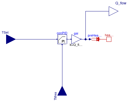
Model of an ideal heater or cooler that tracks a set point using a PI controller. The heater or cooler has a PID controller that regulates the heat added or removed.

To use this model, connect its heat port to the heat port of an air volume, for example, the heat port heaPorAir of Buildings.ThermalZones.EnergyPlus_9_6_0.ThermalZone.

Note that this model can only provide sensible cooling, but no latent cooling.

Extends from Modelica.Blocks.Icons.Block (Basic graphical layout of input/output block).

Parameters

TypeNameDefaultDescription
HeatFlowRateQ_flow_nominal Maximum heat flow rate (positive for heating; negative for cooling) [W]
Controller
SimpleControllercontrollerTypeBuildings.Controls.OBC.CDL.T...Type of controller
Realk1Gain of controller
RealTi120Time constant of integrator block [s]
RealTd0.1Time constant of derivative block [s]

Connectors

TypeNameDescription
input RealInputTSetSet point temperature
input RealInputTMeaMeasured temperature
output RealOutputQ_flowHeat flow rate [W]
HeatPort_bheaPorHeat port

Modelica definition

model IdealHeaterCooler "Model of ideal heater or cooler" extends Modelica.Blocks.Icons.Block; parameter Modelica.Units.SI.HeatFlowRate Q_flow_nominal "Maximum heat flow rate (positive for heating; negative for cooling)"; parameter Buildings.Controls.OBC.CDL.Types.SimpleController controllerType=Buildings.Controls.OBC.CDL.Types.SimpleController.PI "Type of controller"; parameter Real k( min=100*Buildings.Controls.OBC.CDL.Constants.eps)=1 "Gain of controller"; parameter Real Ti( final quantity="Time", final unit="s", min=100*Buildings.Controls.OBC.CDL.Constants.eps)=120 "Time constant of integrator block"; parameter Real Td( final quantity="Time", final unit="s", min=100*Buildings.Controls.OBC.CDL.Constants.eps)=0.1 "Time constant of derivative block"; Buildings.Controls.OBC.CDL.Interfaces.RealInput TSet "Set point temperature"; Buildings.Controls.OBC.CDL.Interfaces.RealInput TMea "Measured temperature"; Buildings.Controls.OBC.CDL.Interfaces.RealOutput Q_flow( final unit="W") "Heat flow rate"; HeatTransfer.Sources.PrescribedHeatFlow preHeaFlo; Modelica.Thermal.HeatTransfer.Interfaces.HeatPort_b heaPor "Heat port"; Buildings.Controls.OBC.CDL.Continuous.PID conPID( final controllerType=controllerType, final k=k, final Ti=Ti, final Td=Td, reverseActing=Q_flow_nominal > 0) "Controller for heat input"; protected Buildings.Controls.OBC.CDL.Continuous.MultiplyByParameter gai( final k=Q_flow_nominal) "Gain for heat flow rate"; equation connect(conPID.u_s,TSet); connect(conPID.u_m,TMea); connect(preHeaFlo.Q_flow,gai.y); connect(gai.u,conPID.y); connect(preHeaFlo.port,heaPor); connect(gai.y,Q_flow); end IdealHeaterCooler;