Buildings.ThermalZones.EnergyPlus_9_6_0.Examples.SmallOffice
Package with VAV models for a small office building
Information
This package contains variable air volume flow models for a office building.
Note
The models Buildings.ThermalZones.EnergyPlus_9_6_0.Examples.SmallOffice.ASHRAE2006Winter and Buildings.ThermalZones.EnergyPlus_9_6_0.Examples.SmallOffice.Guideline36Winter appear to be quite similar to Buildings.Examples.VAVReheat.ASHRAE2006 and Buildings.Examples.VAVReheat.Guideline36, respectively, because they all have the same HVAC system, control sequences, and all have five thermal zones. However, the models in Buildings.ThermalZones.EnergyPlus_9_6_0.Examples.SmallOffice are from the DOE Commercial Reference Building, Small Office, new construction, ASHRAE 90.1-2004, Version 1.3_5.0, whereas the models in Buildings.Examples.VAVReheat are from the DOE Commercial Building Benchmark, Medium Office, new construction, ASHRAE 90.1-2004, version 1.2_4.0. Therefore, the dimensions of the thermal zones in Buildings.ThermalZones.EnergyPlus_9_6_0.Examples.SmallOffice are considerably smaller than in Buildings.Examples.VAVReheat. As the sizing is scaled with the volumes of the thermal zones, the model structure is the same, but the design capacities are different, as is the energy consumption.
Extends from Modelica.Icons.ExamplesPackage (Icon for packages containing runnable examples).
Package Content
| Name | Description |
|---|---|
| Variable air volume flow system with terminal reheat and five thermal zones using a control sequence published by ASHRAE in 2006 | |
| Variable air volume flow system with terminal reheat and five thermal zones using a control sequence published by ASHRAE in 2006 | |
| Variable air volume flow system with terminal reheat and five thermal zones using a control sequence published by ASHRAE in 2006 | |
| Variable air volume flow system with terminal reheat and five thermal zones controlled using an ASHRAE G36 controller | |
| Variable air volume flow system with terminal reheat and five thermal zones controlled using an ASHRAE G36 controller | |
| Variable air volume flow system with terminal reheat and five thermal zones controlled using an ASHRAE G36 controller | |
| Building with constant fresh air and ideal heating/cooling that exactly meets set point | |
| Building with constant fresh air and ideal heating/cooling that exactly meets set point | |
| Building with constant fresh air and ideal heating/cooling that exactly meets set point | |
| Open loop model of one floor | |
| Package with base classes |
 Buildings.ThermalZones.EnergyPlus_9_6_0.Examples.SmallOffice.ASHRAE2006Spring
Variable air volume flow system with terminal reheat and five thermal zones using a control sequence published by ASHRAE in 2006
Information
This is the same model as Buildings.ThermalZones.EnergyPlus_9_6_0.Examples.SmallOffice.ASHRAE2006Winter but configured for simulation of a few days in spring.
Extends from Buildings.ThermalZones.EnergyPlus_9_6_0.Examples.SmallOffice.ASHRAE2006Winter (Variable air volume flow system with terminal reheat and five thermal zones using a control sequence published by ASHRAE in 2006).
Parameters
| Type | Name | Default | Description |
|---|---|---|---|
| replaceable package MediumA | Air | Medium model for air | |
| replaceable package MediumW | Water | Medium model for water | |
| MassFlowRate | mCor_flow_nominal | ACHCor*VRooCor*conv | Design mass flow rate core [kg/s] |
| MassFlowRate | mSou_flow_nominal | ACHSou*VRooSou*conv | Design mass flow rate south [kg/s] |
| MassFlowRate | mEas_flow_nominal | ACHEas*VRooEas*conv | Design mass flow rate east [kg/s] |
| MassFlowRate | mNor_flow_nominal | ACHNor*VRooNor*conv | Design mass flow rate north [kg/s] |
| MassFlowRate | mWes_flow_nominal | ACHWes*VRooWes*conv | Design mass flow rate west [kg/s] |
| Temperature | THeaWatInl_nominal | 45 + 273.15 | Reheat coil nominal inlet water temperature [K] |
| Real | ACHCor | 4 | Design air change per hour core [1/h] |
| Real | ACHSou | 4 | Design air change per hour south [1/h] |
| Real | ACHEas | 6 | Design air change per hour east [1/h] |
| Real | ACHNor | 4 | Design air change per hour north [1/h] |
| Real | ACHWes | 6 | Design air change per hour west [1/h] |
Modelica definition
Buildings.ThermalZones.EnergyPlus_9_6_0.Examples.SmallOffice.ASHRAE2006Summer
Variable air volume flow system with terminal reheat and five thermal zones using a control sequence published by ASHRAE in 2006
Information
This is the same model as Buildings.ThermalZones.EnergyPlus_9_6_0.Examples.SmallOffice.ASHRAE2006Winter but configured for simulation of a few days in spring.
Extends from Buildings.ThermalZones.EnergyPlus_9_6_0.Examples.SmallOffice.ASHRAE2006Winter (Variable air volume flow system with terminal reheat and five thermal zones using a control sequence published by ASHRAE in 2006).
Parameters
| Type | Name | Default | Description |
|---|---|---|---|
| replaceable package MediumA | Air | Medium model for air | |
| replaceable package MediumW | Water | Medium model for water | |
| MassFlowRate | mCor_flow_nominal | ACHCor*VRooCor*conv | Design mass flow rate core [kg/s] |
| MassFlowRate | mSou_flow_nominal | ACHSou*VRooSou*conv | Design mass flow rate south [kg/s] |
| MassFlowRate | mEas_flow_nominal | ACHEas*VRooEas*conv | Design mass flow rate east [kg/s] |
| MassFlowRate | mNor_flow_nominal | ACHNor*VRooNor*conv | Design mass flow rate north [kg/s] |
| MassFlowRate | mWes_flow_nominal | ACHWes*VRooWes*conv | Design mass flow rate west [kg/s] |
| Temperature | THeaWatInl_nominal | 45 + 273.15 | Reheat coil nominal inlet water temperature [K] |
| Real | ACHCor | 4 | Design air change per hour core [1/h] |
| Real | ACHSou | 4 | Design air change per hour south [1/h] |
| Real | ACHEas | 6 | Design air change per hour east [1/h] |
| Real | ACHNor | 4 | Design air change per hour north [1/h] |
| Real | ACHWes | 6 | Design air change per hour west [1/h] |
Modelica definition
Buildings.ThermalZones.EnergyPlus_9_6_0.Examples.SmallOffice.ASHRAE2006Winter
Variable air volume flow system with terminal reheat and five thermal zones using a control sequence published by ASHRAE in 2006
Information
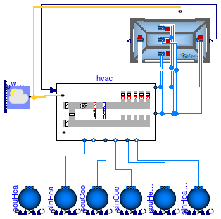
This model consist of an HVAC system, a building envelope model and a model for air flow through building leakage and through open doors.
The HVAC system is a variable air volume (VAV) flow system with economizer and a heating and cooling coil in the air handler unit. There is also a reheat coil and an air damper in each of the five zone inlet branches. The figure below shows the schematic diagram of the HVAC system

See the model Buildings.Examples.VAVReheat.BaseClasses.PartialHVAC for a description of the HVAC system, and see the model Buildings.ThermalZones.EnergyPlus_9_6_0.Examples.SmallOffice.BaseClasses.Floor for a description of the building envelope.
The control is an implementation of the control sequence VAV 2A2-21232 of the Sequences of Operation for Common HVAC Systems (ASHRAE, 2006). In this control sequence, the supply fan speed is regulated based on the duct static pressure. The return fan controller tracks the supply fan air flow rate. The duct static pressure is adjusted so that at least one VAV damper is 90% open. The economizer dampers are modulated to track the setpoint for the mixed air dry bulb temperature. Priority is given to maintain a minimum outside air volume flow rate. In each zone, the VAV damper is adjusted to meet the room temperature setpoint for cooling, or fully opened during heating. The room temperature setpoint for heating is tracked by varying the water flow rate through the reheat coil. There is also a finite state machine that transitions the mode of operation of the HVAC system between the modes occupied, unoccupied off, unoccupied night set back, unoccupied warm-up and unoccupied pre-cool. In the VAV model, all air flows are computed based on the duct static pressure distribution and the performance curves of the fans. Local loop control is implemented using proportional and proportional-integral controllers, while the supervisory control is implemented using a finite state machine.
A similar model but with a different control sequence can be found in Buildings.ThermalZones.EnergyPlus_9_6_0.Examples.SmallOffice.Guideline36Winter.
References
ASHRAE. Sequences of Operation for Common HVAC Systems. ASHRAE, Atlanta, GA, 2006.
Extends from Modelica.Icons.Example (Icon for runnable examples), Buildings.Examples.VAVReheat.BaseClasses.HVACBuilding (Partial model that contains the HVAC and building model).
Parameters
| Type | Name | Default | Description |
|---|---|---|---|
| replaceable package MediumA | Air | Medium model for air | |
| replaceable package MediumW | Water | Medium model for water | |
| MassFlowRate | mCor_flow_nominal | ACHCor*VRooCor*conv | Design mass flow rate core [kg/s] |
| MassFlowRate | mSou_flow_nominal | ACHSou*VRooSou*conv | Design mass flow rate south [kg/s] |
| MassFlowRate | mEas_flow_nominal | ACHEas*VRooEas*conv | Design mass flow rate east [kg/s] |
| MassFlowRate | mNor_flow_nominal | ACHNor*VRooNor*conv | Design mass flow rate north [kg/s] |
| MassFlowRate | mWes_flow_nominal | ACHWes*VRooWes*conv | Design mass flow rate west [kg/s] |
| Temperature | THeaWatInl_nominal | 45 + 273.15 | Reheat coil nominal inlet water temperature [K] |
| Real | ACHCor | 4 | Design air change per hour core [1/h] |
| Real | ACHSou | 4 | Design air change per hour south [1/h] |
| Real | ACHEas | 6 | Design air change per hour east [1/h] |
| Real | ACHNor | 4 | Design air change per hour north [1/h] |
| Real | ACHWes | 6 | Design air change per hour west [1/h] |
Modelica definition
Buildings.ThermalZones.EnergyPlus_9_6_0.Examples.SmallOffice.Guideline36Spring
Variable air volume flow system with terminal reheat and five thermal zones controlled using an ASHRAE G36 controller
Information
This is the same model as Buildings.ThermalZones.EnergyPlus_9_6_0.Examples.SmallOffice.Guideline36Winter but configured for simulation of a few days in spring.
Extends from Buildings.ThermalZones.EnergyPlus_9_6_0.Examples.SmallOffice.Guideline36Winter (Variable air volume flow system with terminal reheat and five thermal zones controlled using an ASHRAE G36 controller).
Parameters
| Type | Name | Default | Description |
|---|---|---|---|
| replaceable package MediumA | Air | Medium model for air | |
| replaceable package MediumW | Water | Medium model for water | |
| MassFlowRate | mCor_flow_nominal | ACHCor*VRooCor*conv | Design mass flow rate core [kg/s] |
| MassFlowRate | mSou_flow_nominal | ACHSou*VRooSou*conv | Design mass flow rate south [kg/s] |
| MassFlowRate | mEas_flow_nominal | ACHEas*VRooEas*conv | Design mass flow rate east [kg/s] |
| MassFlowRate | mNor_flow_nominal | ACHNor*VRooNor*conv | Design mass flow rate north [kg/s] |
| MassFlowRate | mWes_flow_nominal | ACHWes*VRooWes*conv | Design mass flow rate west [kg/s] |
| Temperature | THeaWatInl_nominal | 45 + 273.15 | Reheat coil nominal inlet water temperature [K] |
| Real | ACHCor | 4 | Design air change per hour core [1/h] |
| Real | ACHSou | 4 | Design air change per hour south [1/h] |
| Real | ACHEas | 6 | Design air change per hour east [1/h] |
| Real | ACHNor | 4 | Design air change per hour north [1/h] |
| Real | ACHWes | 6 | Design air change per hour west [1/h] |
Modelica definition
Buildings.ThermalZones.EnergyPlus_9_6_0.Examples.SmallOffice.Guideline36Summer
Variable air volume flow system with terminal reheat and five thermal zones controlled using an ASHRAE G36 controller
Information
This is the same model as Buildings.ThermalZones.EnergyPlus_9_6_0.Examples.SmallOffice.Guideline36Winter but configured for simulation of a few days in summer.
Extends from Buildings.ThermalZones.EnergyPlus_9_6_0.Examples.SmallOffice.Guideline36Winter (Variable air volume flow system with terminal reheat and five thermal zones controlled using an ASHRAE G36 controller).
Parameters
| Type | Name | Default | Description |
|---|---|---|---|
| replaceable package MediumA | Air | Medium model for air | |
| replaceable package MediumW | Water | Medium model for water | |
| MassFlowRate | mCor_flow_nominal | ACHCor*VRooCor*conv | Design mass flow rate core [kg/s] |
| MassFlowRate | mSou_flow_nominal | ACHSou*VRooSou*conv | Design mass flow rate south [kg/s] |
| MassFlowRate | mEas_flow_nominal | ACHEas*VRooEas*conv | Design mass flow rate east [kg/s] |
| MassFlowRate | mNor_flow_nominal | ACHNor*VRooNor*conv | Design mass flow rate north [kg/s] |
| MassFlowRate | mWes_flow_nominal | ACHWes*VRooWes*conv | Design mass flow rate west [kg/s] |
| Temperature | THeaWatInl_nominal | 45 + 273.15 | Reheat coil nominal inlet water temperature [K] |
| Real | ACHCor | 4 | Design air change per hour core [1/h] |
| Real | ACHSou | 4 | Design air change per hour south [1/h] |
| Real | ACHEas | 6 | Design air change per hour east [1/h] |
| Real | ACHNor | 4 | Design air change per hour north [1/h] |
| Real | ACHWes | 6 | Design air change per hour west [1/h] |
Modelica definition
Buildings.ThermalZones.EnergyPlus_9_6_0.Examples.SmallOffice.Guideline36Winter
Variable air volume flow system with terminal reheat and five thermal zones controlled using an ASHRAE G36 controller
Information
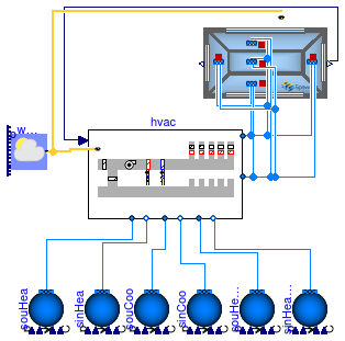
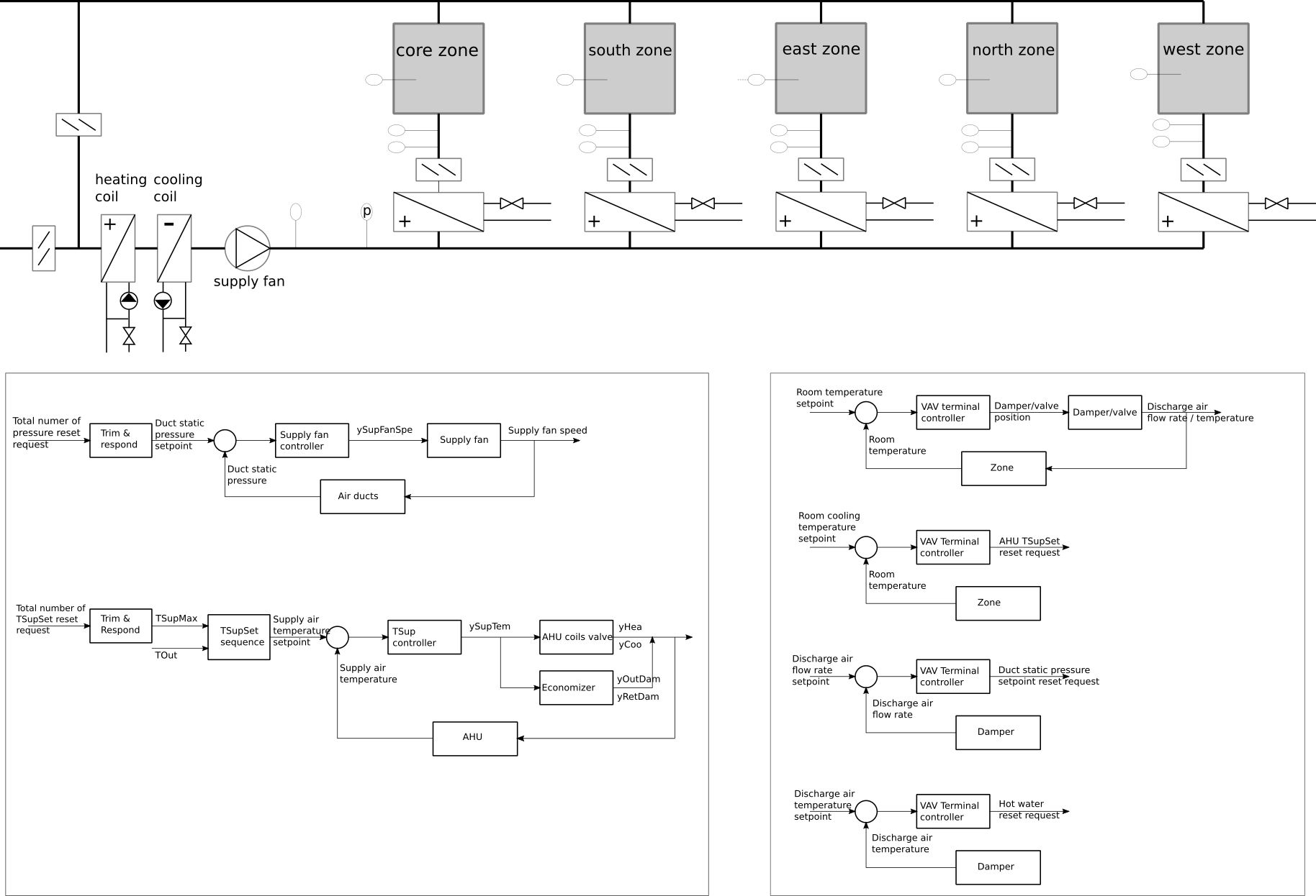
This model consist of an HVAC system, a building envelope model and a model for air flow through building leakage and through open doors.
The HVAC system is a variable air volume (VAV) flow system with economizer and a heating and cooling coil in the air handler unit. There is also a reheat coil and an air damper in each of the five zone inlet branches.
See the model Buildings.Examples.VAVReheat.BaseClasses.PartialHVAC for a description of the HVAC system, and see the model Buildings.ThermalZones.EnergyPlus_9_6_0.Examples.SmallOffice.BaseClasses.Floor for a description of the building envelope.
The control is based on ASHRAE Guideline 36, and implemented using the sequences from the library Buildings.Controls.OBC.ASHRAE.G36_PR1 for multi-zone VAV systems with economizer. The schematic diagram of the HVAC and control sequence is shown in the figure below.
A similar model but with a different control sequence can be found in Buildings.ThermalZones.EnergyPlus_9_6_0.Examples.SmallOffice.ASHRAE2006Winter.. Note that this model, because of the frequent time sampling, has longer computing time than Buildings.Examples.VAVReheat.ASHRAE2006. The reason is that the time integrator cannot make large steps because it needs to set a time step each time the control samples its input.
Extends from Modelica.Icons.Example (Icon for runnable examples), Buildings.Examples.VAVReheat.BaseClasses.HVACBuilding (Partial model that contains the HVAC and building model).
Parameters
| Type | Name | Default | Description |
|---|---|---|---|
| replaceable package MediumA | Air | Medium model for air | |
| replaceable package MediumW | Water | Medium model for water | |
| MassFlowRate | mCor_flow_nominal | ACHCor*VRooCor*conv | Design mass flow rate core [kg/s] |
| MassFlowRate | mSou_flow_nominal | ACHSou*VRooSou*conv | Design mass flow rate south [kg/s] |
| MassFlowRate | mEas_flow_nominal | ACHEas*VRooEas*conv | Design mass flow rate east [kg/s] |
| MassFlowRate | mNor_flow_nominal | ACHNor*VRooNor*conv | Design mass flow rate north [kg/s] |
| MassFlowRate | mWes_flow_nominal | ACHWes*VRooWes*conv | Design mass flow rate west [kg/s] |
| Temperature | THeaWatInl_nominal | 45 + 273.15 | Reheat coil nominal inlet water temperature [K] |
| Real | ACHCor | 4 | Design air change per hour core [1/h] |
| Real | ACHSou | 4 | Design air change per hour south [1/h] |
| Real | ACHEas | 6 | Design air change per hour east [1/h] |
| Real | ACHNor | 4 | Design air change per hour north [1/h] |
| Real | ACHWes | 6 | Design air change per hour west [1/h] |
Modelica definition
 Buildings.ThermalZones.EnergyPlus_9_6_0.Examples.SmallOffice.IdealHeatingCoolingSpring
Building with constant fresh air and ideal heating/cooling that exactly meets set point
Information
This is the same model as Buildings.ThermalZones.EnergyPlus_9_6_0.Examples.SmallOffice.IdealHeatingCoolingWinter but configured for simulation of a few days in summer.
Extends from Buildings.ThermalZones.EnergyPlus_9_6_0.Examples.SmallOffice.IdealHeatingCoolingWinter (Building with constant fresh air and ideal heating/cooling that exactly meets set point).
Parameters
| Type | Name | Default | Description |
|---|---|---|---|
| replaceable package Medium | Air | Medium for air | |
| String | weaName | Modelica.Utilities.Files.loa... | Name of the weather file |
Connectors
| Type | Name | Description |
|---|---|---|
| Bus | weaBus | Weather data bus |
Modelica definition
Buildings.ThermalZones.EnergyPlus_9_6_0.Examples.SmallOffice.IdealHeatingCoolingSummer
Building with constant fresh air and ideal heating/cooling that exactly meets set point
Information
This is the same model as Buildings.ThermalZones.EnergyPlus_9_6_0.Examples.SmallOffice.IdealHeatingCoolingWinter but configured for simulation of a few days in summer.
Extends from Buildings.ThermalZones.EnergyPlus_9_6_0.Examples.SmallOffice.IdealHeatingCoolingWinter (Building with constant fresh air and ideal heating/cooling that exactly meets set point).
Parameters
| Type | Name | Default | Description |
|---|---|---|---|
| replaceable package Medium | Air | Medium for air | |
| String | weaName | Modelica.Utilities.Files.loa... | Name of the weather file |
Connectors
| Type | Name | Description |
|---|---|---|
| Bus | weaBus | Weather data bus |
Modelica definition
Buildings.ThermalZones.EnergyPlus_9_6_0.Examples.SmallOffice.IdealHeatingCoolingWinter
Building with constant fresh air and ideal heating/cooling that exactly meets set point
Information
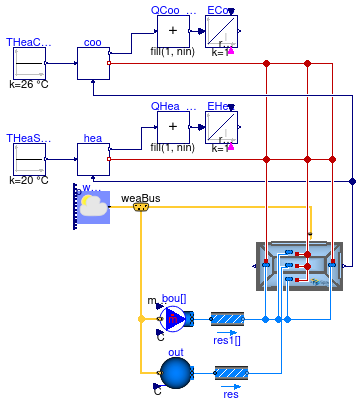
Test case of the small office DOE reference building without an HVAC system but an ideal heating/cooling device that exactly meets the load.
Extends from Buildings.ThermalZones.EnergyPlus_9_6_0.Examples.SmallOffice.Unconditioned (Open loop model of one floor).
Parameters
| Type | Name | Default | Description |
|---|---|---|---|
| replaceable package Medium | Air | Medium for air | |
| String | weaName | Modelica.Utilities.Files.loa... | Name of the weather file |
Connectors
| Type | Name | Description |
|---|---|---|
| Bus | weaBus | Weather data bus |
Modelica definition
Buildings.ThermalZones.EnergyPlus_9_6_0.Examples.SmallOffice.Unconditioned
Open loop model of one floor
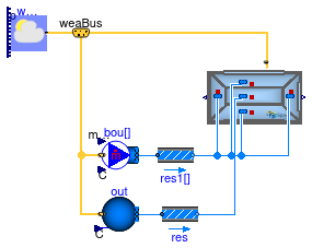
Information
Test case of the small office DOE reference building without an HVAC system. Each thermal zone has a constant air flow rate of unconditioned outside air.
Extends from Modelica.Icons.Example (Icon for runnable examples).
Parameters
| Type | Name | Default | Description |
|---|---|---|---|
| replaceable package Medium | Buildings.Media.Air | Medium for air | |
| String | weaName | Modelica.Utilities.Files.loa... | Name of the weather file |
Connectors
| Type | Name | Description |
|---|---|---|
| replaceable package Medium | Medium for air | |
| Bus | weaBus | Weather data bus |