Package with examples that illustrate the use of the EnergyPlus objects
Information
This package contains example models that illustrate the use of the EnergyPlus objects.
All example models use an EnergyPlus model for a single family house.
The house has one conditioned zone, an unconditioned living room, and a garage.
Extends from Modelica.Icons.ExamplesPackage (Icon for packages containing runnable examples).
Package Content
| Name |
Description |
 AirHeating AirHeating
|
Example model with an air-based heating system that conditions a thermal zone in EnergyPlus |
| EquipmentSchedule
|
Example model with a schedule that overrides a schedule in EnergyPlus |
| LightsControl
|
Example model with one actuator that controls the lights in EnergyPlus |
| RadiantHeatingCooling_TRoom
|
Example model with one thermal zone with a radiant floor where the cooling is controlled based on the room air temperature |
| RadiantHeatingCooling_TSurface
|
Example model with one thermal zone with a radiant floor where the cooling is controlled based on the surface temperature set point |
| RadiantHeatingWithGroundHeatTransfer
|
Example model with one thermal zone with a radiant floor and ground heat transfer modeled in Modelica |
| ShadeControl
|
Example model with one actuator that controls a shade in EnergyPlus |
| Unconditioned
|
Example model with one unconditoned zone simulated in Modelica, and the other two unconditioned zones simulated in EnergyPlus |
Example model with an air-based heating system that conditions a thermal zone in EnergyPlus
Information
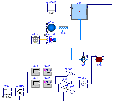
Example of one building with one thermal zone
in which the room air temperature is controlled with a PI controller.
Heating is provided through recirculated air.
The control output is used to compute the set point for the supply air
temperature, which is met by the heating coil.
The setpoint for the room air temperature changes between day and night.
The fan is either off, or operating on stage 1 or 2, depending on the output
of the room temperature controller.
The zone also has a constant air infiltration flow rate.
Note that for simplicity, the model has no cooling system. Therefore, in summer, the house overheats.
Extends from Modelica.Icons.Example (Icon for runnable examples).
Parameters
| Type | Name | Default | Description |
|---|
| MassFlowRate | mOut_flow_nominal | 0.3*VRoo*1.2/3600 | Outdoor air mass flow rate, assuming constant infiltration air flow rate [kg/s] |
| MassFlowRate | mRec_flow_nominal | 8*VRoo*1.2/3600 | Nominal mass flow rate for recirculated air [kg/s] |
Modelica definition
model AirHeating
extends Modelica.Icons.Example;
package Medium=
Buildings.Media.Air
;
inner Building building(
idfName=
Modelica.Utilities.Files.loadResource(
"modelica://Buildings/Resources/Data/ThermalZones/EnergyPlus_9_6_0/Examples/SingleFamilyHouse_TwoSpeed_ZoneAirBalance/SingleFamilyHouse_TwoSpeed_ZoneAirBalance.idf"),
weaName=
Modelica.Utilities.Files.loadResource(
"modelica://Buildings/Resources/weatherdata/USA_IL_Chicago-OHare.Intl.AP.725300_TMY3.mos"),
epwName=
Modelica.Utilities.Files.loadResource(
"modelica://Buildings/Resources/weatherdata/USA_IL_Chicago-OHare.Intl.AP.725300_TMY3.epw"),
computeWetBulbTemperature=false)
;
constant Modelica.Units.SI.Volume VRoo=453.138 ;
constant Modelica.Units.SI.Area AFlo=185.834
;
parameter Modelica.Units.SI.MassFlowRate mOut_flow_nominal=0.3*VRoo*1.2/3600
;
parameter Modelica.Units.SI.MassFlowRate mRec_flow_nominal=8*VRoo*1.2/3600
;
Buildings.ThermalZones.EnergyPlus_9_6_0.ThermalZone zon(
redeclare package Medium=Medium,
zoneName="LIVING ZONE",
nPorts=4)
;
Fluid.Movers.FlowControlled_m_flow fan(
redeclare package Medium=Medium,
energyDynamics=Modelica.Fluid.Types.Dynamics.SteadyState,
m_flow_nominal=mRec_flow_nominal,
nominalValuesDefineDefaultPressureCurve=true)
;
Controls.OBC.CDL.Continuous.Sources.Pulse TSet(
shift(
displayUnit="h")=21600,
amplitude=6,
period(
displayUnit="d")=86400,
offset=273.15+16,
y(unit="K",
displayUnit="degC"))
;
Controls.OBC.CDL.Continuous.PID conPID(
controllerType=Buildings.Controls.OBC.CDL.Types.SimpleController.PI,
k=1,
Ti(
displayUnit="min")=1800,
yMax=1,
yMin=0,
u_s(
unit="K",
displayUnit="degC"),
u_m(
unit="K",
displayUnit="degC"))
;
Fluid.HeatExchangers.Heater_T hea(
redeclare final package Medium=Medium,
m_flow_nominal=mRec_flow_nominal,
dp_nominal=200,
tau=0,
show_T=true)
;
Fluid.Sources.Boundary_pT pAtm(
redeclare package Medium=Medium,
nPorts=1)
;
Fluid.FixedResistances.PressureDrop duc(
redeclare package Medium=Medium,
allowFlowReversal=false,
linearized=true,
from_dp=true,
dp_nominal=100,
m_flow_nominal=mOut_flow_nominal)
;
Fluid.Sources.MassFlowSource_WeatherData freshAir(
redeclare package Medium=Medium,
m_flow=mOut_flow_nominal,
nPorts=1)
;
Controls.OBC.CDL.Continuous.Hysteresis sta1(
uLow=0.05,
uHigh=0.5)
;
Controls.OBC.CDL.Conversions.BooleanToReal mSetFan1_flow(
realTrue=mRec_flow_nominal/2)
;
Controls.OBC.CDL.Continuous.Hysteresis sta2(
uLow=0.5,
uHigh=0.75)
;
Controls.OBC.CDL.Conversions.BooleanToReal mSetFan2_flow(
realTrue=mRec_flow_nominal/2)
;
Controls.OBC.CDL.Continuous.Add m_fan_set
;
Controls.OBC.CDL.Continuous.Add TAirLvgSet
;
Controls.OBC.CDL.Continuous.AddParameter TSupMin(
p=2)
;
Modelica.Blocks.Sources.Constant qIntGai[3](
each k=0)
;
Controls.OBC.CDL.Continuous.MultiplyByParameter gai(
final k=8) ;
initial equation
assert(
abs(
VRoo-zon.V) < 0.01,
"Zone volume VRoo differs from volume returned by EnergyPlus.");
assert(
abs(
AFlo-zon.AFlo) < 0.01,
"Zone floor area AFlo differs from area returned by EnergyPlus.");
equation
connect(TSet.y,conPID.u_s);
connect(conPID.u_m,zon.TAir);
connect(fan.port_b,hea.port_a);
connect(building.weaBus,freshAir.weaBus);
connect(duc.port_a,zon.ports[1]);
connect(freshAir.ports[1],zon.ports[2]);
connect(fan.port_a,zon.ports[3]);
connect(hea.port_b,zon.ports[4]);
connect(duc.port_b,pAtm.ports[1]);
connect(conPID.y,sta1.u);
connect(sta1.y,mSetFan1_flow.u);
connect(conPID.y,sta2.u);
connect(sta2.y,mSetFan2_flow.u);
connect(mSetFan2_flow.y,m_fan_set.u1);
connect(mSetFan1_flow.y,m_fan_set.u2);
connect(m_fan_set.y,fan.m_flow_in);
connect(TAirLvgSet.y,hea.TSet);
connect(zon.TAir,TSupMin.u);
connect(TSupMin.y,TAirLvgSet.u2);
connect(zon.qGai_flow, qIntGai.y);
connect(conPID.y, gai.u);
connect(gai.y, TAirLvgSet.u1);
end AirHeating;
Example model with a schedule that overrides a schedule in EnergyPlus
Information
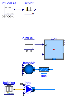
Example model that demonstrates how to override a schedule in EnergyPlus.
The model overrides the EnergyPlus schedule INTERMITTENT,
which is used by EnergyPlus to control the equipment in the thermal zone.
Extends from Buildings.ThermalZones.EnergyPlus_9_6_0.Examples.SingleFamilyHouse.Unconditioned (Example model with one unconditoned zone simulated in Modelica, and the other two unconditioned zones simulated in EnergyPlus).
Parameters
| Type | Name | Default | Description |
|---|
| Volume | VRoo | 453.1 | Room volume [m3] |
| MassFlowRate | m_flow_nominal | VRoo*1.2*0.3/3600 | Nominal mass flow rate [kg/s] |
Modelica definition
Example model with one actuator that controls the lights in EnergyPlus
Information
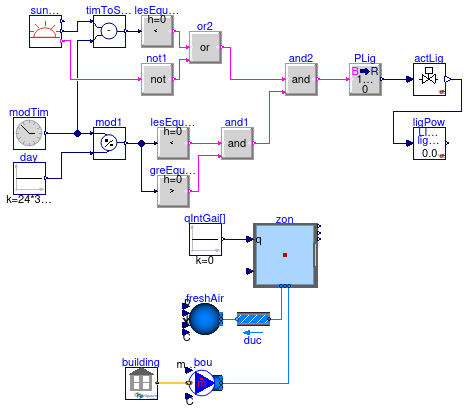
Example of a building that uses an EMS actuator to assign the lighting power in EnergyPlus.
The lights are on 30 minutes before sunset, and remain on until 22:00.
Extends from Buildings.ThermalZones.EnergyPlus_9_6_0.Examples.SingleFamilyHouse.Unconditioned (Example model with one unconditoned zone simulated in Modelica, and the other two unconditioned zones simulated in EnergyPlus).
Parameters
| Type | Name | Default | Description |
|---|
| Volume | VRoo | 453.1 | Room volume [m3] |
| MassFlowRate | m_flow_nominal | VRoo*1.2*0.3/3600 | Nominal mass flow rate [kg/s] |
Modelica definition
model LightsControl
extends Buildings.ThermalZones.EnergyPlus_9_6_0.Examples.SingleFamilyHouse.Unconditioned;
Buildings.ThermalZones.EnergyPlus_9_6_0.Actuator actLig(
unit=Buildings.ThermalZones.EnergyPlus_9_6_0.Types.Units.Power,
variableName="LIVING ZONE Lights",
componentType="Lights",
controlType="Electricity Rate")
;
Buildings.ThermalZones.EnergyPlus_9_6_0.OutputVariable ligPow(
name="Lights Electricity Rate",
key="LIVING ZONE Lights",
isDirectDependent=true,
y(
final unit="W"))
;
Controls.OBC.CDL.Utilities.SunRiseSet sunRiseSet(
lat=0.73268921998722,
lon=-1.5344934783534,
timZon=-21600)
;
Controls.OBC.CDL.Continuous.Modulo mod1
;
Controls.OBC.CDL.Continuous.Sources.Constant day(
k=24*3600)
;
Controls.OBC.CDL.Continuous.Sources.ModelTime modTim
;
Controls.OBC.CDL.Continuous.LessThreshold lesEquThr(
t=22*3600)
;
Controls.OBC.CDL.Continuous.Subtract timToSunSet
;
Controls.OBC.CDL.Continuous.LessThreshold lesEquThr1(
t=1800)
;
Controls.OBC.CDL.Logical.Or or2
;
Controls.OBC.CDL.Logical.And and2
;
Controls.OBC.CDL.Conversions.BooleanToReal PLig(
realTrue=1000)
;
Controls.OBC.CDL.Logical.Not not1
;
Controls.OBC.CDL.Continuous.GreaterThreshold greEquThr(
t=12*3600)
;
Controls.OBC.CDL.Logical.And and1
;
equation
connect(day.y,mod1.u2);
connect(mod1.u1,modTim.y);
connect(mod1.y,lesEquThr.u);
connect(sunRiseSet.nextSunSet,timToSunSet.u1);
connect(modTim.y,timToSunSet.u2);
connect(lesEquThr1.u,timToSunSet.y);
connect(lesEquThr1.y,or2.u1);
connect(or2.y,and2.u1);
connect(and2.y,PLig.u);
connect(actLig.u,PLig.y);
connect(not1.y,or2.u2);
connect(not1.u,sunRiseSet.sunUp);
connect(greEquThr.u,mod1.y);
connect(greEquThr.y,and1.u2);
connect(and1.u1,lesEquThr.y);
connect(and1.y,and2.u2);
connect(actLig.y,ligPow.directDependency);
end LightsControl;
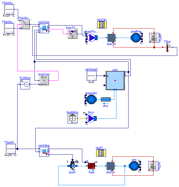
Example model with one thermal zone with a radiant floor where the cooling is controlled based on the room air temperature
Information
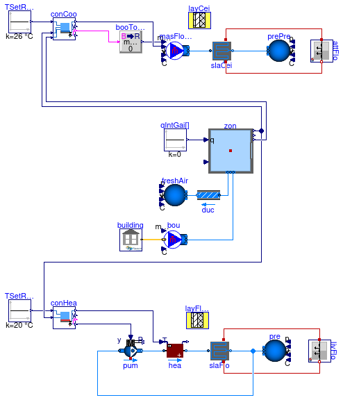
Model that uses EnergyPlus for the simulation of a building with one thermal zone
that has a radiant ceiling, used for cooling, and a radiant floor, used for heating.
The EnergyPlus model has one conditioned zone that is above ground. This conditioned zone
has an unconditioned attic.
The model is constructed by extending
Buildings.ThermalZones.EnergyPlus_9_6_0.Examples.SingleFamilyHouse.RadiantHeatingWithGroundHeatTransfer
and adding the radiant ceiling.
The next section explains how the radiant ceiling is configured.
Coupling of radiant ceiling to EnergyPlus model
The radiant ceiling is modeled in the instance slaCei at the top of the schematic model view,
using the model
Buildings.Fluid.HeatExchangers.RadiantSlabs.ParallelCircuitsSlab.
This instance models the heat transfer from the surface of the attic floor to the ceiling of the living room.
In this example, the construction is defined by the instance layCei.
(See the
Buildings.Fluid.HeatExchangers.RadiantSlabs.UsersGuide
for how to configure a radiant slab.)
In this example, the surfaces slaCei.surf_a (upward-facing) and
slaCei.surf_a (downward-facing)
are connected to the instance attFlo.
Because attFlo models the floor of the attic, rather than the ceiling
of the living room,
the heat port slaCei.surf_a is connected to attFlo.heaPorFro, which is the
front-facing surface, e.g., the floor.
Similarly, slaCei.surf_b is connected to attFlo.heaPorBac, which is the
back-facing surface, e.g., the ceiling of the living room.
The mass flow rate of the slab is constant if the cooling is operating.
A P controller computes the control signal to track a set point for the room temperature.
The controller uses a hysteresis to switch the mass flow rate on or off.
The control signal is also used to set the set point for the water supply temperature to the slab.
This temperature is limited by the dew point of the zone air to avoid condensation.
See also the model
Buildings.ThermalZones.EnergyPlus_9_6_0.Examples.SingleFamilyHouse.RadiantHeatingCooling_TSurface
which is controlled to track a set point for the surface temperature.
Coupling of radiant floor to EnergyPlus model
The radiant floor is modeled in the instance slaFlo at the bottom of the schematic model view,
using the model
Buildings.Fluid.HeatExchangers.RadiantSlabs.ParallelCircuitsSlab.
This instance models the heat transfer from surface of the floor to the lower surface of the slab.
In this example, the construction is defined by the instance layFloSoi.
(See the
Buildings.Fluid.HeatExchangers.RadiantSlabs.UsersGuide
for how to configure a radiant slab.)
In this example, the surfaces slaFlo.surf_a and
slaFlo.surf_b
are connected to the instance
flo.
In EnergyPlus, the surface flo.heaPorBac is connected
to the boundary condition of the soil because this building has no basement.
Note that the floor construction is modeled with 2 m of soil because the soil temperature
in EnergyPlus is assumed to be undisturbed.
Extends from Buildings.ThermalZones.EnergyPlus_9_6_0.Examples.SingleFamilyHouse.Unconditioned (Example model with one unconditoned zone simulated in Modelica, and the other two unconditioned zones simulated in EnergyPlus).
Parameters
| Type | Name | Default | Description |
|---|
| Volume | VRoo | 453.1 | Room volume [m3] |
| MassFlowRate | m_flow_nominal | VRoo*1.2*0.3/3600 | Nominal mass flow rate [kg/s] |
| HeatFlowRate | QHea_flow_nominal | 7500 | Nominal heat flow rate for heating [W] |
| MassFlowRate | mHea_flow_nominal | QHea_flow_nominal/4200/10 | Design water mass flow rate for heating [kg/s] |
| HeatFlowRate | QCoo_flow_nominal | -5000 | Nominal heat flow rate for cooling [W] |
| MassFlowRate | mCoo_flow_nominal | -QCoo_flow_nominal/4200/5 | Design water mass flow rate for heating [kg/s] |
| Generic | layFloSoi | layFloSoi(nLay=4, material={... | Material layers from surface a to b (8cm concrete, 10 cm insulation, 20 cm concrete, 200 cm soil, below which is the undisturbed soil assumed) |
| Generic | layCei | layCei(nLay=4, material={Bui... | Material layers from surface a to b (8cm concrete, 10 cm insulation, 18+2 cm concrete) |
Modelica definition
model RadiantHeatingCooling_TRoom
extends Buildings.ThermalZones.EnergyPlus_9_6_0.Examples.SingleFamilyHouse.Unconditioned
( building(
idfName=
Modelica.Utilities.Files.loadResource(
"modelica://Buildings/Resources/Data/ThermalZones/EnergyPlus_9_6_0/Examples/SingleFamilyHouse_TwoSpeed_ZoneAirBalance/SingleFamilyHouse_TwoSpeed_ZoneAirBalance_aboveSoil.idf")));
package MediumW=
Buildings.Media.Water
;
constant Modelica.Units.SI.Area AFlo=185.8 ;
parameter Modelica.Units.SI.HeatFlowRate QHea_flow_nominal=7500
;
parameter Modelica.Units.SI.MassFlowRate mHea_flow_nominal=QHea_flow_nominal/
4200/10 ;
parameter Modelica.Units.SI.HeatFlowRate QCoo_flow_nominal=-5000
;
parameter Modelica.Units.SI.MassFlowRate mCoo_flow_nominal=-QCoo_flow_nominal
/4200/5 ;
parameter HeatTransfer.Data.OpaqueConstructions.Generic layFloSoi(nLay=4,
material={
Buildings.HeatTransfer.Data.Solids.Concrete(x=0.08),
Buildings.HeatTransfer.Data.Solids.InsulationBoard(x=0.10),
Buildings.HeatTransfer.Data.Solids.Concrete(x=0.2),
HeatTransfer.Data.Solids.Generic(
x=2,
k=1.3,
c=800,
d=1500)})
;
parameter HeatTransfer.Data.OpaqueConstructions.Generic layCei(
nLay=4,
material={
Buildings.HeatTransfer.Data.Solids.Concrete(x=0.08),
Buildings.HeatTransfer.Data.Solids.InsulationBoard(x=0.10),
Buildings.HeatTransfer.Data.Solids.Concrete(x=0.18),
Buildings.HeatTransfer.Data.Solids.Concrete(x=0.02)})
;
Fluid.HeatExchangers.RadiantSlabs.ParallelCircuitsSlab slaFlo(
redeclare package Medium = MediumW,
allowFlowReversal=false,
layers=layFloSoi,
iLayPip=1,
pipe=
Fluid.Data.Pipes.PEX_DN_15(),
sysTyp=Buildings.Fluid.HeatExchangers.RadiantSlabs.Types.SystemType.Floor,
disPip=0.2,
nCir=3,
A=AFlo,
m_flow_nominal=mHea_flow_nominal,
energyDynamics=Modelica.Fluid.Types.Dynamics.FixedInitial,
from_dp=true,
show_T=true) ;
Fluid.Sources.Boundary_ph pre(
redeclare package Medium=MediumW,
p(displayUnit="Pa")=300000,
nPorts=1)
;
Controls.OBC.CDL.Continuous.Sources.Constant TSetRooHea(
k(
final unit="K",
displayUnit="degC")=293.15,
y(
final unit="K",
displayUnit="degC"))
;
Fluid.Movers.SpeedControlled_y pum(
redeclare package Medium=MediumW,
energyDynamics=Modelica.Fluid.Types.Dynamics.SteadyState,
per(
pressure(
V_flow=2*{0,mHea_flow_nominal}/1000,
dp=2*{14000,0}),
speed_nominal,
constantSpeed,
speeds),
inputType=Buildings.Fluid.Types.InputType.Continuous)
;
Fluid.HeatExchangers.Heater_T hea(
redeclare final package Medium=MediumW,
allowFlowReversal=false,
m_flow_nominal=mHea_flow_nominal,
dp_nominal=10000,
show_T=true,
energyDynamics=Modelica.Fluid.Types.Dynamics.FixedInitial)
;
Fluid.HeatExchangers.RadiantSlabs.ParallelCircuitsSlab slaCei(
redeclare package Medium=MediumW,
allowFlowReversal=false,
layers=layCei,
iLayPip=3,
pipe=
Fluid.Data.Pipes.PEX_DN_15(),
sysTyp=Buildings.Fluid.HeatExchangers.RadiantSlabs.Types.SystemType.Ceiling_Wall_or_Capillary,
disPip=0.2,
nCir=4,
A=AFlo,
m_flow_nominal=mCoo_flow_nominal,
energyDynamics=Modelica.Fluid.Types.Dynamics.FixedInitial,
show_T=true)
;
Fluid.Sources.Boundary_ph prePre(
redeclare package Medium=MediumW,
nPorts=1,
p(displayUnit="Pa")=300000)
;
Fluid.Sources.MassFlowSource_T masFloSouCoo(
redeclare package Medium=MediumW,
use_m_flow_in=true,
use_T_in=true,
nPorts=1)
;
Controls.OBC.CDL.Continuous.Sources.Constant TSetRooCoo(
k(
final unit="K",
displayUnit="degC")=299.15,
y(
final unit="K",
displayUnit="degC")) ;
Controls.OBC.CDL.Conversions.BooleanToReal booToRea(
realTrue=mCoo_flow_nominal)
;
Buildings.ThermalZones.EnergyPlus_9_6_0.OpaqueConstruction attFlo(
surfaceName="Attic:LivingFloor")
;
Buildings.ThermalZones.EnergyPlus_9_6_0.OpaqueConstruction livFlo(surfaceName="Living:Floor")
;
Controls.OBC.RadiantSystems.Heating.HighMassSupplyTemperature_TRoom conHea(
TSupSet_max=318.15)
;
Controls.OBC.RadiantSystems.Cooling.HighMassSupplyTemperature_TRoomRelHum
conCoo(TSupSet_min=289.15) ;
initial equation
assert(
abs(
AFlo-zon.AFlo) < 0.1,
"Floor area AFlo differs from EnergyPlus floor area.");
equation
connect(masFloSouCoo.ports[1],slaCei.port_a);
connect(prePre.ports[1],slaCei.port_b);
connect(booToRea.y,masFloSouCoo.m_flow_in);
connect(attFlo.heaPorFro,slaCei.surf_a);
connect(slaCei.surf_b,attFlo.heaPorBac);
connect(TSetRooHea.y, conHea.TRooSet);
connect(pum.y, conHea.yPum);
connect(pum.port_b,hea.port_a);
connect(hea.port_b,slaFlo.port_a);
connect(livFlo.heaPorFro, slaFlo.surf_a);
connect(slaFlo.surf_b, livFlo.heaPorBac);
connect(zon.TAir, conHea.TRoo);
connect(slaFlo.port_b,pum.port_a);
connect(slaFlo.port_b,pre.ports[1]);
connect(conHea.TSupSet, hea.TSet);
connect(conCoo.on, booToRea.u);
connect(conCoo.TRooSet, TSetRooCoo.y);
connect(zon.TAir, conCoo.TRoo);
connect(conCoo.phiRoo, zon.phi);
connect(conCoo.TSupSet, masFloSouCoo.T_in);
end RadiantHeatingCooling_TRoom;
Example model with one thermal zone with a radiant floor where the cooling is controlled based on the surface temperature set point
Information
Model that uses EnergyPlus for the simulation of a building with one thermal zone
that has a radiant ceiling, used for cooling, and a radiant floor, used for heating.
The EnergyPlus model has one conditioned zone that is above ground. This conditioned zone
has an unconditioned attic.
The model is constructed by extending
Buildings.ThermalZones.EnergyPlus_9_6_0.Examples.SingleFamilyHouse.RadiantHeatingWithGroundHeatTransfer
and adding the radiant ceiling.
The next section explains how the radiant ceiling is configured.
Coupling of radiant ceiling to EnergyPlus model
The radiant ceiling is modeled in the instance slaCei at the top of the schematic model view,
using the model
Buildings.Fluid.HeatExchangers.RadiantSlabs.ParallelCircuitsSlab.
This instance models the heat transfer from the surface of the attic floor to the ceiling of the living room.
In this example, the construction is defined by the instance layCei.
(See the
Buildings.Fluid.HeatExchangers.RadiantSlabs.UsersGuide
for how to configure a radiant slab.)
In this example, the surfaces slaCei.surf_a (upward-facing) and
slaCei.surf_a (downward-facing)
are connected to the instance attFlo.
Because attFlo models the floor of the attic, rather than the ceiling
of the living room,
the heat port slaCei.surf_a is connected to attFlo.heaPorFro, which is the
front-facing surface, e.g., the floor.
Similarly, slaCei.surf_b is connected to attFlo.heaPorBac, which is the
back-facing surface, e.g., the ceiling of the living room.
Cooling is enabled if the room temperature is a certain value above the heating set point temperature.
(Note that for simplicity this model has no night set back. If night set back where enabled, one needs to
guard against switchin on the cooling if the heating set point is reset.)
The mass flow rate of the slab is constant if the cooling is operating.
A P controller computes the control signal to maintain a set point for the surface temperature.
The controller uses a hysteresis to switch the mass flow rate on or off.
The control signal is also used to set the set point for the water supply temperature to the slab.
This temperature is limited by the dew point of the zone air to avoid condensation.
See also the model
Buildings.ThermalZones.EnergyPlus_9_6_0.Examples.SingleFamilyHouse.RadiantHeatingCooling_TRoom
which is controlled to track a set point for the room temperature.
Coupling of radiant floor to EnergyPlus model
The radiant floor is modeled in the instance slaFlo at the bottom of the schematic model view,
using the model
Buildings.Fluid.HeatExchangers.RadiantSlabs.ParallelCircuitsSlab.
This instance models the heat transfer from surface of the floor to the lower surface of the slab.
In this example, the construction is defined by the instance layFloSoi.
(See the
Buildings.Fluid.HeatExchangers.RadiantSlabs.UsersGuide
for how to configure a radiant slab.)
In this example, the surfaces slaFlo.surf_a and
slaFlo.surf_b
are connected to the instance
flo.
In EnergyPlus, the surface flo.heaPorBac is connected
to the boundary condition of the soil because this building has no basement.
Note that the floor construction is modeled with 2 m of soil because the soil temperature
in EnergyPlus is assumed to be undisturbed.
Extends from Buildings.ThermalZones.EnergyPlus_9_6_0.Examples.SingleFamilyHouse.Unconditioned (Example model with one unconditoned zone simulated in Modelica, and the other two unconditioned zones simulated in EnergyPlus).
Parameters
| Type | Name | Default | Description |
|---|
| Volume | VRoo | 453.1 | Room volume [m3] |
| MassFlowRate | m_flow_nominal | VRoo*1.2*0.3/3600 | Nominal mass flow rate [kg/s] |
| HeatFlowRate | QHea_flow_nominal | 7500 | Nominal heat flow rate for heating [W] |
| MassFlowRate | mHea_flow_nominal | QHea_flow_nominal/4200/10 | Design water mass flow rate for heating [kg/s] |
| HeatFlowRate | QCoo_flow_nominal | -5000 | Nominal heat flow rate for cooling [W] |
| MassFlowRate | mCoo_flow_nominal | -QCoo_flow_nominal/4200/5 | Design water mass flow rate for heating [kg/s] |
| Generic | layFloSoi | layFloSoi(nLay=4, material={... | Material layers from surface a to b (8cm concrete, 10 cm insulation, 20 cm concrete, 200 cm soil, below which is the undisturbed soil assumed) |
| Generic | layCei | layCei(nLay=4, material={Bui... | Material layers from surface a to b (8cm concrete, 10 cm insulation, 18+2 cm concrete) |
Modelica definition
model RadiantHeatingCooling_TSurface
extends Buildings.ThermalZones.EnergyPlus_9_6_0.Examples.SingleFamilyHouse.Unconditioned
( building(
idfName=
Modelica.Utilities.Files.loadResource(
"modelica://Buildings/Resources/Data/ThermalZones/EnergyPlus_9_6_0/Examples/SingleFamilyHouse_TwoSpeed_ZoneAirBalance/SingleFamilyHouse_TwoSpeed_ZoneAirBalance_aboveSoil.idf")));
package MediumW=
Buildings.Media.Water
;
constant Modelica.Units.SI.Area AFlo=185.8 ;
parameter Modelica.Units.SI.HeatFlowRate QHea_flow_nominal=7500
;
parameter Modelica.Units.SI.MassFlowRate mHea_flow_nominal=QHea_flow_nominal/
4200/10 ;
parameter Modelica.Units.SI.HeatFlowRate QCoo_flow_nominal=-5000
;
parameter Modelica.Units.SI.MassFlowRate mCoo_flow_nominal=-QCoo_flow_nominal
/4200/5 ;
parameter HeatTransfer.Data.OpaqueConstructions.Generic layFloSoi(nLay=4,
material={
Buildings.HeatTransfer.Data.Solids.Concrete(x=0.08),
Buildings.HeatTransfer.Data.Solids.InsulationBoard(x=0.10),
Buildings.HeatTransfer.Data.Solids.Concrete(x=0.2),
HeatTransfer.Data.Solids.Generic(
x=2,
k=1.3,
c=800,
d=1500)})
;
parameter HeatTransfer.Data.OpaqueConstructions.Generic layCei(
nLay=4,
material={
Buildings.HeatTransfer.Data.Solids.Concrete(x=0.08),
Buildings.HeatTransfer.Data.Solids.InsulationBoard(x=0.10),
Buildings.HeatTransfer.Data.Solids.Concrete(x=0.18),
Buildings.HeatTransfer.Data.Solids.Concrete(x=0.02)})
;
Fluid.HeatExchangers.RadiantSlabs.ParallelCircuitsSlab slaFlo(
redeclare package Medium = MediumW,
allowFlowReversal=false,
layers=layFloSoi,
iLayPip=1,
pipe=
Fluid.Data.Pipes.PEX_DN_15(),
sysTyp=Buildings.Fluid.HeatExchangers.RadiantSlabs.Types.SystemType.Floor,
disPip=0.2,
nCir=3,
A=AFlo,
m_flow_nominal=mHea_flow_nominal,
energyDynamics=Modelica.Fluid.Types.Dynamics.FixedInitial,
from_dp=true,
show_T=true) ;
Fluid.Sources.Boundary_ph pre(
redeclare package Medium=MediumW,
p(displayUnit="Pa")=300000,
nPorts=1)
;
Controls.OBC.CDL.Continuous.Sources.Constant TSetRooHea(
k(
final unit="K",
displayUnit="degC")=293.15,
y(
final unit="K",
displayUnit="degC"))
;
Fluid.Movers.SpeedControlled_y pum(
redeclare package Medium=MediumW,
energyDynamics=Modelica.Fluid.Types.Dynamics.SteadyState,
per(
pressure(
V_flow=2*{0,mHea_flow_nominal}/1000,
dp=2*{14000,0}),
speed_nominal,
constantSpeed,
speeds),
inputType=Buildings.Fluid.Types.InputType.Continuous)
;
Fluid.HeatExchangers.Heater_T hea(
redeclare final package Medium=MediumW,
allowFlowReversal=false,
m_flow_nominal=mHea_flow_nominal,
dp_nominal=10000,
show_T=true,
energyDynamics=Modelica.Fluid.Types.Dynamics.FixedInitial)
;
Fluid.HeatExchangers.RadiantSlabs.ParallelCircuitsSlab slaCei(
redeclare package Medium=MediumW,
allowFlowReversal=false,
layers=layCei,
iLayPip=3,
pipe=
Fluid.Data.Pipes.PEX_DN_15(),
sysTyp=Buildings.Fluid.HeatExchangers.RadiantSlabs.Types.SystemType.Ceiling_Wall_or_Capillary,
disPip=0.2,
nCir=4,
A=AFlo,
m_flow_nominal=mCoo_flow_nominal,
energyDynamics=Modelica.Fluid.Types.Dynamics.FixedInitial,
show_T=true)
;
Fluid.Sources.Boundary_ph prePre(
redeclare package Medium=MediumW,
nPorts=1,
p(displayUnit="Pa")=300000)
;
Fluid.Sources.MassFlowSource_T masFloSouCoo(
redeclare package Medium=MediumW,
use_m_flow_in=true,
use_T_in=true,
nPorts=1)
;
Buildings.Controls.OBC.CDL.Continuous.Sources.Constant TSetSurCooOn(k(
final unit="K",
displayUnit="degC") = 293.15, y(
final unit="K", displayUnit="degC"))
;
Controls.OBC.CDL.Conversions.BooleanToReal booToRea(
realTrue=mCoo_flow_nominal)
;
Buildings.ThermalZones.EnergyPlus_9_6_0.OpaqueConstruction attFlo(
surfaceName="Attic:LivingFloor")
;
Buildings.ThermalZones.EnergyPlus_9_6_0.OpaqueConstruction livFlo(surfaceName="Living:Floor")
;
Controls.OBC.RadiantSystems.Heating.HighMassSupplyTemperature_TRoom conHea(
TSupSet_max=318.15)
;
Controls.OBC.RadiantSystems.Cooling.HighMassSupplyTemperature_TSurRelHum
conCoo(TSupSet_min=289.15) ;
Modelica.Thermal.HeatTransfer.Sensors.TemperatureSensor TSur
;
Buildings.Controls.OBC.CDL.Continuous.Sources.Constant TSetSurOff(k(
final unit="K",
displayUnit="degC") = 303.15, y(
final unit="K", displayUnit="degC"))
;
Controls.OBC.CDL.Continuous.Greater enaCoo(h=1)
;
Buildings.Controls.OBC.CDL.Continuous.Switch TSetSurCoo
;
Controls.OBC.CDL.Continuous.AddParameter TOffSet(p=3)
;
initial equation
assert(
abs(
AFlo-zon.AFlo) < 0.1,
"Floor area AFlo differs from EnergyPlus floor area.");
equation
connect(masFloSouCoo.ports[1],slaCei.port_a);
connect(prePre.ports[1],slaCei.port_b);
connect(booToRea.y,masFloSouCoo.m_flow_in);
connect(attFlo.heaPorFro,slaCei.surf_a);
connect(slaCei.surf_b,attFlo.heaPorBac);
connect(TSetRooHea.y, conHea.TRooSet);
connect(pum.y, conHea.yPum);
connect(pum.port_b,hea.port_a);
connect(hea.port_b,slaFlo.port_a);
connect(livFlo.heaPorFro, slaFlo.surf_a);
connect(slaFlo.surf_b, livFlo.heaPorBac);
connect(slaFlo.port_b,pum.port_a);
connect(zon.TAir, conHea.TRoo);
connect(slaFlo.port_b,pre.ports[1]);
connect(conHea.TSupSet, hea.TSet);
connect(conCoo.on, booToRea.u);
connect(zon.TAir, conCoo.TRoo);
connect(conCoo.phiRoo, zon.phi);
connect(conCoo.TSupSet, masFloSouCoo.T_in);
connect(attFlo.heaPorBac, TSur.port);
connect(TSur.T, conCoo.TSur);
connect(zon.TAir, enaCoo.u1);
connect(TSetSurCooOn.y, TSetSurCoo.u1);
connect(TSetSurOff.y, TSetSurCoo.u3);
connect(enaCoo.y, TSetSurCoo.u2);
connect(TSetSurCoo.y, conCoo.TSurSet);
connect(enaCoo.u2, TOffSet.y);
connect(TOffSet.u, TSetRooHea.y);
end RadiantHeatingCooling_TSurface;
Example model with one thermal zone with a radiant floor and ground heat transfer modeled in Modelica
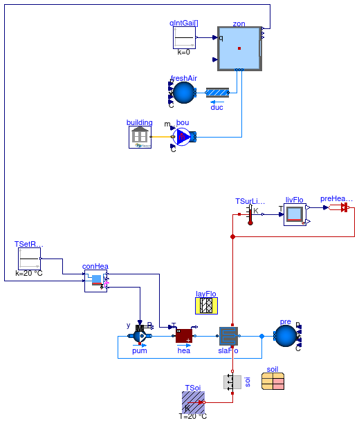
Information
Model that uses EnergyPlus for the simulation of a building with one thermal zone
that has a radiant floor, used for heating.
The EnergyPlus model has one conditioned zone that is above ground. This conditioned zone
has an unconditioned attic.
This model has no cooling and hence will overheat in summer. See
Buildings.ThermalZones.EnergyPlus_9_6_0.Examples.SingleFamilyHouse.RadiantHeatingCooling_TRoom
for a similar model that also has cooling.
The next section explains how the radiant floor is configured.
Coupling of radiant floor to EnergyPlus model
The radiant floor is modeled in the instance slaFlo at the bottom of the schematic model view,
using the model
Buildings.Fluid.HeatExchangers.RadiantSlabs.ParallelCircuitsSlab.
This instance models the heat transfer from surface of the floor to the lower surface of the slab.
In this example, the construction is defined by the instance layFlo.
(See the
Buildings.Fluid.HeatExchangers.RadiantSlabs.UsersGuide
for how to configure a radiant slab.)
In this example, the surface slaFlo.surf_a is connected to the instance
flo.
This connection is made by measuring the surface temperture, sending this as an input to
livFlo, and setting the heat flow rate at the surface from the instance livFlo
to the surface slaFlo.surf_a.
The underside of the slab is connected to the heat conduction model soi
which computes the heat transfer to the soil because this building has no basement.
Extends from Buildings.ThermalZones.EnergyPlus_9_6_0.Examples.SingleFamilyHouse.Unconditioned (Example model with one unconditoned zone simulated in Modelica, and the other two unconditioned zones simulated in EnergyPlus).
Parameters
| Type | Name | Default | Description |
|---|
| Volume | VRoo | 453.1 | Room volume [m3] |
| MassFlowRate | m_flow_nominal | VRoo*1.2*0.3/3600 | Nominal mass flow rate [kg/s] |
| HeatFlowRate | QHea_flow_nominal | 12000 | Nominal heat flow rate for heating [W] |
| MassFlowRate | mHea_flow_nominal | QHea_flow_nominal/4200/10 | Design water mass flow rate for heating [kg/s] |
| Generic | layFlo | layFlo(nLay=3, material={Bui... | Material layers from surface a to b (8cm concrete, 10 cm insulation, 20 cm concrete) |
| Generic | soil | soil(x=2, k=1.3, c=800, d=15... | Soil properties |
Modelica definition
model RadiantHeatingWithGroundHeatTransfer
extends Buildings.ThermalZones.EnergyPlus_9_6_0.Examples.SingleFamilyHouse.Unconditioned;
package MediumW=
Buildings.Media.Water
;
constant Modelica.Units.SI.Area AFlo=185.8 ;
parameter Modelica.Units.SI.HeatFlowRate QHea_flow_nominal=12000
;
parameter Modelica.Units.SI.MassFlowRate mHea_flow_nominal=QHea_flow_nominal/
4200/10 ;
parameter HeatTransfer.Data.OpaqueConstructions.Generic layFlo(
nLay=3,
material={
Buildings.HeatTransfer.Data.Solids.Concrete(x=0.08),
Buildings.HeatTransfer.Data.Solids.InsulationBoard(x=0.10),
Buildings.HeatTransfer.Data.Solids.Concrete(x=0.2)})
;
parameter HeatTransfer.Data.Solids.Generic soil(
x=2,
k=1.3,
c=800,
d=1500)
;
Buildings.ThermalZones.EnergyPlus_9_6_0.ZoneSurface livFlo(
surfaceName="Living:Floor")
;
Fluid.HeatExchangers.RadiantSlabs.ParallelCircuitsSlab slaFlo(
redeclare package Medium=MediumW,
allowFlowReversal=false,
layers=layFlo,
iLayPip=1,
pipe=
Fluid.Data.Pipes.PEX_DN_15(),
sysTyp=Buildings.Fluid.HeatExchangers.RadiantSlabs.Types.SystemType.Floor,
disPip=0.2,
nCir=3,
A=AFlo,
m_flow_nominal=mHea_flow_nominal,
energyDynamics=Modelica.Fluid.Types.Dynamics.FixedInitial,
from_dp=true,
show_T=true)
;
Fluid.Sources.Boundary_ph pre(
redeclare package Medium=MediumW,
nPorts=1,
p(displayUnit="Pa")=300000)
;
HeatTransfer.Sources.PrescribedHeatFlow preHeaLivFlo
;
Modelica.Thermal.HeatTransfer.Sensors.TemperatureSensor TSurLivFlo
;
Controls.OBC.CDL.Continuous.Sources.Constant TSetRooHea(
k(
final unit="K",
displayUnit="degC")=293.15,
y(
final unit="K",
displayUnit="degC"))
;
Fluid.Movers.SpeedControlled_y pum(
redeclare package Medium=MediumW,
energyDynamics=Modelica.Fluid.Types.Dynamics.SteadyState,
per(
pressure(
V_flow=2*{0,mHea_flow_nominal}/1000,
dp=2*{14000,0}),
speed_nominal,
constantSpeed,
speeds),
inputType=Buildings.Fluid.Types.InputType.Continuous)
;
Fluid.HeatExchangers.Heater_T hea(
redeclare final package Medium=MediumW,
allowFlowReversal=false,
m_flow_nominal=mHea_flow_nominal,
dp_nominal=10000,
show_T=true,
energyDynamics=Modelica.Fluid.Types.Dynamics.FixedInitial)
;
HeatTransfer.Conduction.SingleLayer soi(
A=AFlo,
material=soil,
steadyStateInitial=true,
stateAtSurface_a=false,
stateAtSurface_b=false,
T_a_start=283.15,
T_b_start=283.75)
;
Modelica.Thermal.HeatTransfer.Sources.FixedTemperature TSoi(
T=293.15)
;
Controls.OBC.RadiantSystems.Heating.HighMassSupplyTemperature_TRoom conHea(
TSupSet_max=318.15)
;
initial equation
assert(
abs(
AFlo-zon.AFlo) < 0.1,
"Floor area AFlo differs from EnergyPlus floor area.");
equation
connect(slaFlo.port_b,pre.ports[1]);
connect(livFlo.Q_flow,preHeaLivFlo.Q_flow);
connect(preHeaLivFlo.port,slaFlo.surf_a);
connect(TSurLivFlo.port,slaFlo.surf_a);
connect(hea.port_b,slaFlo.port_a);
connect(pum.port_b,hea.port_a);
connect(pum.port_a,slaFlo.port_b);
connect(TSurLivFlo.T,livFlo.T);
connect(TSoi.port,soi.port_a);
connect(soi.port_b,slaFlo.surf_b);
connect(conHea.TRoo, zon.TAir);
connect(TSetRooHea.y, conHea.TRooSet);
connect(conHea.yPum, pum.y);
connect(conHea.TSupSet, hea.TSet);
end RadiantHeatingWithGroundHeatTransfer;
Example model with one actuator that controls a shade in EnergyPlus
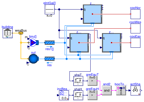
Information
Example of a building that uses an EMS actuator.
The building has three thermal zones that are simulated in EnergyPlus.
In the EnergyPlus model, the west-facing thermal zone has
a window blind that is open if its control signal is 0 or closed if it is 6.
The control sequence obtains
the room air temperature of the west-facing zone
from the Modelica instance zonWes,
and connects it to a hysteresis block that switches its output to
true if the zone temperature is above 24°C,
and to false if it drops below 23°C.
The instance incBeaSou obtains from EnergyPlus the
incident solar beam radiation on the outside of the window, and feeds it
into a hysteresis block that outputs true if its input exceeds
200 W/m2, and switches to false if it drops
below 10 W/m2.
The instance actSha connects to the EMS actuator in EnergyPlus
that activates this shade.
If both outputs of the hysteresis blocks
are true, then the EnergyPlus shade actuator is deployed by
setting the input of actSha to 6.
Otherwise, the input is set to 0.
To the right of the model, there are three idealized cooling systems
that keep the room air temperature below 25°C in each of the three
zones.
Also, each zone is connected to a constant, unconditioned outside air supply.
The internal heat gains are set to zero in Modelica because these are
specified in the EnergyPlus model.
Extends from Modelica.Icons.Example (Icon for runnable examples).
Parameters
| Type | Name | Default | Description |
|---|
| MassFlowRate | m_flow_nominal[:] | 0.3*1.2/3600*{113.3,113.3,16... | Design mass flow rate [kg/s] |
Connectors
| Type | Name | Description |
|---|
| Bus | weaBus | Weather data bus |
Modelica definition
model ShadeControl
extends Modelica.Icons.Example;
package Medium=
Buildings.Media.Air
;
inner Building building(
idfName=
Modelica.Utilities.Files.loadResource(
"modelica://Buildings/Resources/Data/ThermalZones/EnergyPlus_9_6_0/Examples/EMSWindowShadeControl/EMSWindowShadeControl.idf"),
epwName=
Modelica.Utilities.Files.loadResource(
"modelica://Buildings/Resources/weatherdata/USA_IL_Chicago-OHare.Intl.AP.725300_TMY3.epw"),
weaName=
Modelica.Utilities.Files.loadResource(
"modelica://Buildings/Resources/weatherdata/USA_IL_Chicago-OHare.Intl.AP.725300_TMY3.mos"))
;
parameter Modelica.Units.SI.MassFlowRate m_flow_nominal[:]=0.3*1.2/3600*{
113.3,113.3,169.9} ;
Modelica.Blocks.Sources.Constant qIntGai[3](
each k=0)
;
Buildings.ThermalZones.EnergyPlus_9_6_0.ThermalZone zonWes(
redeclare package Medium=Medium,
zoneName="West Zone",
nPorts=2)
;
Buildings.ThermalZones.EnergyPlus_9_6_0.ThermalZone zonEas(
redeclare package Medium=Medium,
zoneName="EAST ZONE",
nPorts=2)
;
Buildings.ThermalZones.EnergyPlus_9_6_0.ThermalZone zonNor(
redeclare package Medium=Medium,
zoneName="NORTH ZONE",
nPorts=2)
;
Buildings.ThermalZones.EnergyPlus_9_6_0.Actuator actSha(
unit=Buildings.ThermalZones.EnergyPlus_9_6_0.Types.Units.Normalized,
variableName="Zn001:Wall001:Win001",
componentType="Window Shading Control",
controlType="Control Status")
;
Buildings.ThermalZones.EnergyPlus_9_6_0.OutputVariable incBeaSou(
name="Surface Outside Face Incident Beam Solar Radiation Rate per Area",
key="Zn001:Wall001:Win001",
y(
final unit="W/m2"))
;
Buildings.Controls.OBC.Shade.Shade_T shaT(
THigh=297.15,
TLow=295.15)
;
Buildings.Controls.OBC.Shade.Shade_H shaH(
HHigh=200,
HLow=10)
;
Buildings.Controls.OBC.CDL.Logical.And and2;
Buildings.Controls.OBC.CDL.Continuous.GreaterThreshold greEquT(
t=0.5)
;
Buildings.Controls.OBC.CDL.Continuous.GreaterThreshold greEquH(
t=0.5)
;
Buildings.Controls.OBC.CDL.Conversions.BooleanToReal booToRea(
realTrue=6)
;
Buildings.Fluid.Sources.MassFlowSource_WeatherData bou[3](
redeclare each package Medium=Medium,
m_flow=m_flow_nominal,
each nPorts=1)
;
Buildings.Fluid.Sources.Outside out(
redeclare package Medium=Medium,
nPorts=1)
;
Buildings.Fluid.FixedResistances.PressureDrop res(
redeclare package Medium=Medium,
m_flow_nominal=
sum(m_flow_nominal),
dp_nominal=10,
linearized=true);
Buildings.Fluid.FixedResistances.PressureDrop res1[3](
redeclare each package Medium=Medium,
m_flow_nominal=m_flow_nominal,
each dp_nominal=10,
each linearized=true)
;
Buildings.BoundaryConditions.WeatherData.Bus weaBus
;
Cooling cooNor
;
Cooling cooWes
;
Cooling cooEas
;
equation
connect(qIntGai.y,zonNor.qGai_flow);
connect(qIntGai.y,zonEas.qGai_flow);
connect(qIntGai.y,zonWes.qGai_flow);
connect(shaT.y,greEquT.u);
connect(shaH.y,greEquH.u);
connect(greEquT.y,and2.u1);
connect(greEquH.y,and2.u2);
connect(and2.y,booToRea.u);
connect(actSha.u,booToRea.y);
connect(shaT.T,zonWes.TAir);
connect(shaH.H,incBeaSou.y);
connect(weaBus,out.weaBus);
connect(bou[:].ports[1],res1[:].port_a);
connect(weaBus,bou[1].weaBus);
connect(weaBus,bou[2].weaBus);
connect(weaBus,bou[3].weaBus);
connect(building.weaBus,weaBus);
connect(res1[1].port_b,zonNor.ports[1]);
connect(res1[2].port_b,zonWes.ports[1]);
connect(res1[3].port_b,zonEas.ports[1]);
connect(out.ports[1],res.port_b);
connect(res.port_a,zonNor.ports[2]);
connect(res.port_a,zonWes.ports[2]);
connect(res.port_a,zonEas.ports[2]);
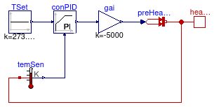
protected
model Cooling
extends Modelica.Blocks.Icons.Block;
HeatTransfer.Sources.PrescribedHeatFlow preHeaFlo
;
Controls.OBC.CDL.Continuous.MultiplyByParameter gai(k=-5000) ;
Controls.OBC.CDL.Continuous.PID conPID(
Ti=120,
reverseActing=false);
Controls.OBC.CDL.Continuous.Sources.Constant TSet(
k=273.15+25)
;
Modelica.Thermal.HeatTransfer.Interfaces.HeatPort_b heaPor
;
Modelica.Thermal.HeatTransfer.Sensors.TemperatureSensor temSen
;
equation
connect(TSet.y,conPID.u_s);
connect(gai.u,conPID.y);
connect(gai.y,preHeaFlo.Q_flow);
connect(preHeaFlo.port,heaPor);
connect(temSen.T,conPID.u_m);
connect(temSen.port,preHeaFlo.port);
end Cooling;
equation
connect(cooNor.heaPor,zonNor.heaPorAir);
connect(cooWes.heaPor,zonWes.heaPorAir);
connect(cooEas.heaPor,zonEas.heaPorAir);
end ShadeControl;
Example model with one unconditoned zone simulated in Modelica, and the other two unconditioned zones simulated in EnergyPlus
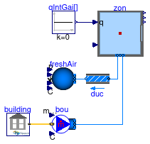
Information
This example models the living room as an unconditioned zone in Modelica.
The living room is connected to a fresh air supply and exhaust.
The heat balance of the air of the other two thermal zones, i.e.,
the attic and the garage, are modeled in EnergyPlus.
Extends from Modelica.Icons.Example (Icon for runnable examples).
Parameters
| Type | Name | Default | Description |
|---|
| Volume | VRoo | 453.1 | Room volume [m3] |
| MassFlowRate | m_flow_nominal | VRoo*1.2*0.3/3600 | Nominal mass flow rate [kg/s] |
Modelica definition
model Unconditioned
extends Modelica.Icons.Example;
package Medium=
Buildings.Media.Air
;
inner Buildings.ThermalZones.EnergyPlus_9_6_0.Building building(
idfName=
Modelica.Utilities.Files.loadResource(
"modelica://Buildings/Resources/Data/ThermalZones/EnergyPlus_9_6_0/Examples/SingleFamilyHouse_TwoSpeed_ZoneAirBalance/SingleFamilyHouse_TwoSpeed_ZoneAirBalance.idf"),
epwName=
Modelica.Utilities.Files.loadResource(
"modelica://Buildings/Resources/weatherdata/USA_IL_Chicago-OHare.Intl.AP.725300_TMY3.epw"),
weaName=
Modelica.Utilities.Files.loadResource(
"modelica://Buildings/Resources/weatherdata/USA_IL_Chicago-OHare.Intl.AP.725300_TMY3.mos"),
usePrecompiledFMU=false,
computeWetBulbTemperature=false)
;
parameter Modelica.Units.SI.Volume VRoo=453.1 ;
parameter Modelica.Units.SI.MassFlowRate m_flow_nominal=VRoo*1.2*0.3/3600
;
Buildings.ThermalZones.EnergyPlus_9_6_0.ThermalZone zon(
redeclare package Medium=Medium,
zoneName="LIVING ZONE",
nPorts=2)
;
Buildings.Fluid.FixedResistances.PressureDrop duc(
redeclare package Medium=Medium,
allowFlowReversal=false,
linearized=true,
from_dp=true,
dp_nominal=100,
m_flow_nominal=m_flow_nominal)
;
Buildings.Fluid.Sources.MassFlowSource_WeatherData bou(
redeclare package Medium=Medium,
nPorts=1,
m_flow=m_flow_nominal)
;
Buildings.Fluid.Sources.Boundary_pT freshAir(
redeclare package Medium=Medium,
nPorts=1)
;
Modelica.Blocks.Sources.Constant qIntGai[3](
each k=0)
;
equation
connect(freshAir.ports[1],duc.port_b);
connect(duc.port_a,zon.ports[1]);
connect(bou.ports[1],zon.ports[2]);
connect(zon.qGai_flow,qIntGai.y);
connect(building.weaBus,bou.weaBus);
end Unconditioned;
Information
Extends from Modelica.Blocks.Icons.Block (Basic graphical layout of input/output block).
Connectors
Modelica definition
 Buildings.ThermalZones.EnergyPlus_9_6_0.Examples.SingleFamilyHouse.AirHeating
 Buildings.ThermalZones.EnergyPlus_9_6_0.Examples.SingleFamilyHouse.ShadeControl
 Buildings.ThermalZones.EnergyPlus_9_6_0.Examples.SingleFamilyHouse.ShadeControl.Cooling