Buildings.Fluid.FMI.ExportContainers.Examples.FMUs
Collection of example models
Information
This package contains examples for the use of models that can be found in Buildings.Fluid.FMI.ExportContainers.
Extends from Modelica.Icons.ExamplesPackage (Icon for packages containing runnable examples).
Package Content
| Name | Description |
|---|---|
| Declaration of an FMU that exports a fan | |
| Declaration of an FMU that exports a flow splitter | |
| Declaration of an FMU that exports a simple convective only HVAC system | |
| Declaration of an FMU that exports a simple convective only HVAC system for two zones | |
| Declaration of an FMU that exports an ideal heater or cooler with prescribed heat flow rate | |
| Declaration of an FMU that exports an ideal heater or cooler with prescribed outlet temperature | |
| Declaration of an FMU that exports an ideal humidifier | |
| Declaration of an FMU that exports a mass flow source and sink | |
| Declaration of an FMU that exports a control volume | |
| Declaration of an FMU that exports a fixed resistance | |
| Declaration of an FMU that exports a flow resistance and control volume | |
| Declaration of an FMU that exports a thermal zone | |
| Declaration of an FMU that exports multiple thermal zones | |
| Declaration of an FMU that exports a block that simply passes all the inputs to the outputs |
 Buildings.Fluid.FMI.ExportContainers.Examples.FMUs.Fan
Declaration of an FMU that exports a fan
Information
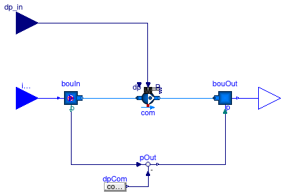
This example demonstrates how to export an FMU with a fluid flow component. The FMU has an instance of Buildings.Fluid.Movers.FlowControlled_dp.
See Buildings.Fluid.FMI.UsersGuide for why there is no model that exports Buildings.Fluid.Movers.FlowControlled_m_flow.
Extends from Buildings.Fluid.FMI.ExportContainers.ReplaceableTwoPort (Container to export thermofluid flow models with two ports as an FMU).
Parameters
| Type | Name | Default | Description |
|---|---|---|---|
| replaceable package Medium | PartialMedium | Medium in the component | |
| Boolean | use_p_in | true | = true to use a pressure from connector, false to output Medium.p_default |
| MassFlowRate | m_flow_nominal | 0.01 | Nominal mass flow rate [kg/s] |
| PressureDifference | dp_nominal | 500 | Pressure drop at nominal mass flow rate [Pa] |
| Assumptions | |||
| Boolean | allowFlowReversal | true | = true to allow flow reversal, false restricts to design direction (inlet -> outlet) |
Connectors
| Type | Name | Description |
|---|---|---|
| replaceable package Medium | Medium in the component | |
| Inlet | inlet | Fluid inlet |
| Outlet | outlet | Fluid outlet |
| input RealInput | dp_in | Prescribed pressure rise [Pa] |
Modelica definition
 Buildings.Fluid.FMI.ExportContainers.Examples.FMUs.FlowSplitter_u
Declaration of an FMU that exports a flow splitter

Information
This example demonstrates how to export an FMU with a fluid flow component. The FMU is an instance of Buildings.Fluid.FMI.FlowSplitter_u.
Extends from Buildings.Fluid.FMI.FlowSplitter_u (Model of a flow splitter that can be exported as an FMU).
Parameters
| Type | Name | Default | Description |
|---|---|---|---|
| replaceable package Medium | PartialMedium | Medium in the component | |
| MassFlowRate | m_flow_nominal[nout] | {0.1,0.2} | Nominal mass flow rate for each outlet [kg/s] |
| Integer | nout | 2 | Number of outlets |
| Boolean | use_p_in | true | = true to use a pressure from connector, false to output Medium.p_default |
Connectors
| Type | Name | Description |
|---|---|---|
| replaceable package Medium | Medium in the component | |
| Inlet | inlet | Fluid inlet |
| Outlet | outlet[nout] | Fluid outlet |
| input RealInput | u[nout] | Control signal for the mass flow rates [1] |
Modelica definition
 Buildings.Fluid.FMI.ExportContainers.Examples.FMUs.HVACZone
Declaration of an FMU that exports a simple convective only HVAC system
Information
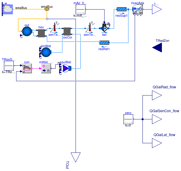
This example demonstrates how to export a model of an HVAC system that only provides convective cooling to a single thermal zone. The HVAC system is adapted from Buildings.Examples.Tutorial.SpaceCooling.System3, but flow resistances have been added to have the same configuration as Buildings.Fluid.FMI.ExportContainers.Examples.FMUs.HVACZones. Having the same configuration is needed for the validation test Buildings.Fluid.FMI.ExportContainers.Validation.RoomHVAC.
The example extends from
Buildings.Fluid.FMI.ExportContainers.HVACZone
which provides the input and output signals that are needed to interface
the acausal HVAC system model with causal connectors of FMI.
The instance hvacAda is the HVAC adapter
that contains on the left a fluid port, and on the right signal ports
which are then used to connect at the top-level of the model to signal
ports which are exposed at the FMU interface.
Extends from Buildings.Fluid.FMI.ExportContainers.HVACZone (Partial block to export an HVAC system that has no radiative component and that serves multiple zones as an FMU).
Parameters
| Type | Name | Default | Description |
|---|---|---|---|
| replaceable package Medium | PartialMedium | Medium in the component | |
| replaceable package MediumA | Buildings.Media.Air | Medium for air | |
| replaceable package MediumW | Buildings.Media.Water | Medium for water | |
| Real | eps | 0.8 | Heat recovery effectiveness |
| Temperature | TASup_nominal | 291.15 | Nominal air temperature supplied to room [K] |
| DimensionlessRatio | wASup_nominal | 0.012 | Nominal air humidity ratio supplied to room [kg/kg] assuming 90% relative humidity [1] |
| Temperature | TRooSet | 297.15 | Nominal room air temperature [K] |
| Temperature | TOut_nominal | 303.15 | Design outlet air temperature [K] |
| Temperature | THeaRecLvg | TOut_nominal - eps*(TOut_nom... | Air temperature leaving the heat recovery [K] |
| DimensionlessRatio | wHeaRecLvg | 0.0135 | Air humidity ratio leaving the heat recovery [kg/kg] [1] |
| Real | UA | 10E3 | Average UA-value of the room [W/K] |
| HeatFlowRate | QRooInt_flow | 1000 | Internal heat gains of the room [W] |
| HeatFlowRate | QRooC_flow_nominal | -QRooInt_flow - UA/30*(TOut_... | Nominal cooling load of the room [W] |
| MassFlowRate | mA_flow_nominal | 1.3*QRooC_flow_nominal/1006/... | Nominal air mass flow rate, increased by factor 1.3 to allow for recovery after temperature setback [kg/s] |
| TemperatureDifference | dTFan | 2 | Estimated temperature raise across fan that needs to be made up by the cooling coil [K] |
| HeatFlowRate | QCoiC_flow_nominal | mA_flow_nominal*(TASup_nomin... | Cooling load of coil, taking into account outside air sensible and latent heat removal [W] |
| Temperature | TWSup_nominal | 285.15 | Water supply temperature [K] |
| Temperature | TWRet_nominal | 289.15 | Water return temperature [K] |
| MassFlowRate | mW_flow_nominal | -QCoiC_flow_nominal/(TWRet_n... | Nominal water mass flow rate [kg/s] |
| ConstantEffectiveness | cooCoi | cooCoi(dp1_nominal=6000, dp2... | Cooling coil (with sensible cooling only) |
| Assumptions | |||
| Boolean | allowFlowReversal | false | = true to allow flow reversal, false restricts to design direction (inlet -> outlet) |
Connectors
| Type | Name | Description |
|---|---|---|
| replaceable package Medium | Medium in the component | |
| Outlet | fluPor[size(hvacAda.fluPor, 1)] | Fluid connector |
| input RealInput | TRadZon | Radiative temperature of the zone [K] |
| output RealOutput | QGaiRad_flow | Radiant heat input into zone (positive if heat gain) [W] |
| output RealOutput | QGaiSenCon_flow | Convective sensible heat input into zone (positive if heat gain) [W] |
| output RealOutput | QGaiLat_flow | Latent heat input into zone (positive if heat gain) [W] |
| replaceable package MediumA | Medium for air | |
| replaceable package MediumW | Medium for water | |
| Bus | weaBus | Weather data bus |
| output RealOutput | TOut | Outdoor temperature [K] |
Modelica definition
 Buildings.Fluid.FMI.ExportContainers.Examples.FMUs.HVACZones
Declaration of an FMU that exports a simple convective only HVAC system for two zones
Information
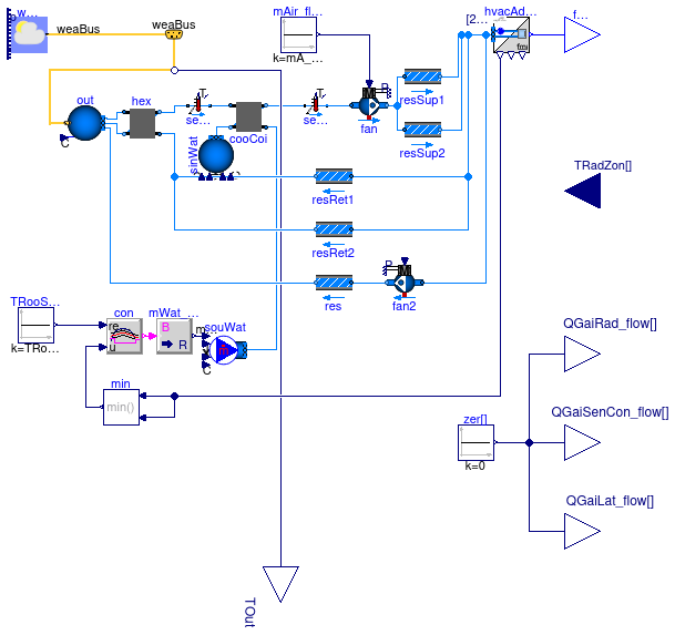
This example demonstrates how to export a model of an HVAC system that only provides convective cooling to two thermal zones. The example is similar to Buildings.Fluid.FMI.ExportContainers.Examples.FMUs.HVACZone except that is serves two thermal zones rather than one.
The example extends from
Buildings.Fluid.FMI.ExportContainers.HVACZones
which provides the input and output signals that are needed to interface
the acausal HVAC system model with causal connectors of FMI.
The instance hvacAda is the HVAC adapter
that contains on the left a fluid port, and on the right signal ports
which are then used to connect at the top-level of the model to signal
ports which are exposed at the FMU interface.
Extends from Buildings.Fluid.FMI.ExportContainers.HVACZones (Partial block to export an HVAC system that has no radiative component and that serves multiple zones as an FMU).
Parameters
| Type | Name | Default | Description |
|---|---|---|---|
| replaceable package Medium | PartialMedium | Medium in the component | |
| Integer | nZon | 2 | Number of thermal zones served by the HVAC system |
| Integer | nPorts | 3 | Number of fluid ports for each zone (must be the same for every zone) |
| replaceable package MediumA | Buildings.Media.Air | Medium for air | |
| replaceable package MediumW | Buildings.Media.Water | Medium for water | |
| Real | eps | 0.8 | Heat recovery effectiveness |
| Temperature | TASup_nominal | 291.15 | Nominal air temperature supplied to room [K] |
| DimensionlessRatio | wASup_nominal | 0.012 | Nominal air humidity ratio supplied to room [kg/kg] assuming 90% relative humidity [1] |
| Temperature | TRooSet | 297.15 | Nominal room air temperature [K] |
| Temperature | TOut_nominal | 303.15 | Design outlet air temperature [K] |
| Temperature | THeaRecLvg | TOut_nominal - eps*(TOut_nom... | Air temperature leaving the heat recovery [K] |
| DimensionlessRatio | wHeaRecLvg | 0.0135 | Air humidity ratio leaving the heat recovery [kg/kg] [1] |
| Real | UA | 10E3 | Average UA-value of the room [W/K] |
| HeatFlowRate | QRooInt_flow | 1000 | Internal heat gains of the room [W] |
| HeatFlowRate | QRooC_flow_nominal | -QRooInt_flow - UA/30*(TOut_... | Nominal cooling load of the room [W] |
| MassFlowRate | mA_flow_nominal | 1.3*QRooC_flow_nominal/1006/... | Nominal air mass flow rate, increased by factor 1.3 to allow for recovery after temperature setback [kg/s] |
| TemperatureDifference | dTFan | 2 | Estimated temperature raise across fan that needs to be made up by the cooling coil [K] |
| HeatFlowRate | QCoiC_flow_nominal | mA_flow_nominal*(TASup_nomin... | Cooling load of coil, taking into account outside air sensible and latent heat removal [W] |
| Temperature | TWSup_nominal | 285.15 | Water supply temperature [K] |
| Temperature | TWRet_nominal | 289.15 | Water return temperature [K] |
| MassFlowRate | mW_flow_nominal | -QCoiC_flow_nominal/(TWRet_n... | Nominal water mass flow rate [kg/s] |
| ConstantEffectiveness | cooCoi | cooCoi(dp1_nominal=6000, dp2... | Cooling coil (with sensible cooling only) |
| Assumptions | |||
| Boolean | allowFlowReversal | false | = true to allow flow reversal, false restricts to design direction (inlet -> outlet) |
Connectors
| Type | Name | Description |
|---|---|---|
| replaceable package Medium | Medium in the component | |
| Outlet | fluPor[nZon, nPorts] | Fluid connectors |
| input RealInput | TRadZon[nZon] | Radiative temperature of the zone [K] |
| output RealOutput | QGaiRad_flow[nZon] | Radiant heat input into the zones (positive if heat gain) [W] |
| output RealOutput | QGaiSenCon_flow[nZon] | Convective sensible heat input into the zones (positive if heat gain) [W] |
| output RealOutput | QGaiLat_flow[nZon] | Latent heat input into the zones (positive if heat gain) [W] |
| replaceable package MediumA | Medium for air | |
| replaceable package MediumW | Medium for water | |
| Bus | weaBus | Weather data bus |
| output RealOutput | TOut | Outdoor temperature [K] |
Modelica definition
 Buildings.Fluid.FMI.ExportContainers.Examples.FMUs.HeaterCooler_u
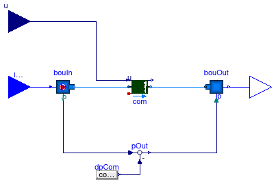
Declaration of an FMU that exports an ideal heater or cooler with prescribed heat flow rate
Information
This example demonstrates how to export an FMU with a heater that takes as an input signal the normalized heat flow rate. The FMU has an instance of Buildings.Fluid.HeatExchangers.HeaterCooler_u.
The mass dynamics has been set to
massDynamics=Modelica.Fluid.Types.Dynamics.SteadyState.
See the
user's guide
for the rationale.
Extends from Buildings.Fluid.FMI.ExportContainers.ReplaceableTwoPort (Container to export thermofluid flow models with two ports as an FMU).
Parameters
| Type | Name | Default | Description |
|---|---|---|---|
| replaceable package Medium | PartialMedium | Medium in the component | |
| Boolean | use_p_in | true | = true to use a pressure from connector, false to output Medium.p_default |
| MassFlowRate | m_flow_nominal | 0.01 | Nominal mass flow rate [kg/s] |
| PressureDifference | dp_nominal | 0 | Pressure [Pa] |
| HeatFlowRate | Q_flow_nominal | 100 | Heat flow rate at u=1, positive for heating [W] |
| Assumptions | |||
| Boolean | allowFlowReversal | true | = true to allow flow reversal, false restricts to design direction (inlet -> outlet) |
Connectors
| Type | Name | Description |
|---|---|---|
| replaceable package Medium | Medium in the component | |
| Inlet | inlet | Fluid inlet |
| Outlet | outlet | Fluid outlet |
| input RealInput | u | Control input [1] |
Modelica definition
 Buildings.Fluid.FMI.ExportContainers.Examples.FMUs.Heater_T
Declaration of an FMU that exports an ideal heater or cooler with prescribed outlet temperature
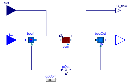
Information
This example demonstrates how to export an FMU with a heater that takes as an input signal the leaving fluid temperature. The FMU has an instance of Buildings.Fluid.HeatExchangers.PrescribedOutlet.
Extends from Buildings.Fluid.FMI.ExportContainers.ReplaceableTwoPort (Container to export thermofluid flow models with two ports as an FMU).
Parameters
| Type | Name | Default | Description |
|---|---|---|---|
| replaceable package Medium | PartialMedium | Medium in the component | |
| Boolean | use_p_in | true | = true to use a pressure from connector, false to output Medium.p_default |
| HeatFlowRate | QMax_flow | Modelica.Constants.inf | Maximum heat flow rate for heating (positive) [W] |
| HeatFlowRate | QMin_flow | -Modelica.Constants.inf | Maximum heat flow rate for cooling (negative) [W] |
| MassFlowRate | m_flow_nominal | 0.01 | Nominal mass flow rate [kg/s] |
| PressureDifference | dp_nominal | 0 | Pressure [Pa] |
| Assumptions | |||
| Boolean | allowFlowReversal | true | = true to allow flow reversal, false restricts to design direction (inlet -> outlet) |
Connectors
| Type | Name | Description |
|---|---|---|
| replaceable package Medium | Medium in the component | |
| Inlet | inlet | Fluid inlet |
| Outlet | outlet | Fluid outlet |
| input RealInput | TSet | Set point temperature of the fluid that leaves port_b [K] |
| output RealOutput | Q_flow | Heat added to the fluid (if flow is from port_a to port_b) [W] |
Modelica definition
Buildings.Fluid.FMI.ExportContainers.Examples.FMUs.Humidifier_u
Declaration of an FMU that exports an ideal humidifier
Information
This example demonstrates how to export an FMU with a humidifier that takes as an input signal the normalized mass flow rate of water that will be added to the medium. The FMU has an instance of Buildings.Fluid.Humidifiers.Humidifier_u.
The mass dynamics has been set to
massDynamics=Modelica.Fluid.Types.Dynamics.SteadyState.
See the
user's guide
for the rationale.
Extends from Buildings.Fluid.FMI.ExportContainers.ReplaceableTwoPort (Container to export thermofluid flow models with two ports as an FMU).
Parameters
| Type | Name | Default | Description |
|---|---|---|---|
| replaceable package Medium | PartialMedium | Medium in the component | |
| Boolean | use_p_in | true | = true to use a pressure from connector, false to output Medium.p_default |
| MassFlowRate | m_flow_nominal | 0.01 | Nominal mass flow rate [kg/s] |
| PressureDifference | dp_nominal | 0 | Pressure [Pa] |
| MassFlowRate | mWat_flow_nominal | 0.01*0.005 | Water mass flow rate at u=1, positive for humidification [kg/s] |
| Assumptions | |||
| Boolean | allowFlowReversal | true | = true to allow flow reversal, false restricts to design direction (inlet -> outlet) |
Connectors
| Type | Name | Description |
|---|---|---|
| replaceable package Medium | Medium in the component | |
| Inlet | inlet | Fluid inlet |
| Outlet | outlet | Fluid outlet |
| input RealInput | u | Control input [1] |
Modelica definition
 Buildings.Fluid.FMI.ExportContainers.Examples.FMUs.IdealSource_m_flow
Declaration of an FMU that exports a mass flow source and sink
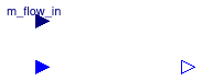
Information
This example demonstrates how to export an FMU that sets the mass flow rate.
Extends from Buildings.Fluid.FMI.ExportContainers.PartialTwoPort (Partial block to be used as a container to export a thermofluid flow model with two ports).
Parameters
| Type | Name | Default | Description |
|---|---|---|---|
| replaceable package Medium | PartialMedium | Medium in the component | |
| Boolean | use_p_in | true | = true to use a pressure from connector, false to output Medium.p_default |
| Assumptions | |||
| Boolean | allowFlowReversal | true | = true to allow flow reversal, false restricts to design direction (inlet -> outlet) |
Connectors
| Type | Name | Description |
|---|---|---|
| replaceable package Medium | Medium in the component | |
| Inlet | inlet | Fluid inlet |
| Outlet | outlet | Fluid outlet |
| input RealInput | m_flow_in | Prescribed mass flow rate [kg/s] |
Modelica definition
 Buildings.Fluid.FMI.ExportContainers.Examples.FMUs.MixingVolume
Declaration of an FMU that exports a control volume
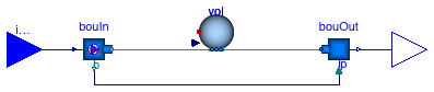
Information
This example demonstrates how to export an FMU with a control volume. The FMU has an instance of Buildings.Fluid.MixingVolumes.MixingVolume.
The mass dynamics has been set to
massDynamics=Modelica.Fluid.Types.Dynamics.SteadyState.
See the
user's guide
for the rationale.
Extends from Buildings.Fluid.FMI.ExportContainers.PartialTwoPort (Partial block to be used as a container to export a thermofluid flow model with two ports).
Parameters
| Type | Name | Default | Description |
|---|---|---|---|
| replaceable package Medium | PartialMedium | Medium in the component | |
| Boolean | use_p_in | true | = true to use a pressure from connector, false to output Medium.p_default |
| Volume | V | 1 | Volume [m3] |
| MassFlowRate | m_flow_nominal | 0.01 | Nominal mass flow rate [kg/s] |
| Assumptions | |||
| Boolean | allowFlowReversal | true | = true to allow flow reversal, false restricts to design direction (inlet -> outlet) |
Connectors
| Type | Name | Description |
|---|---|---|
| replaceable package Medium | Medium in the component | |
| Inlet | inlet | Fluid inlet |
| Outlet | outlet | Fluid outlet |
Modelica definition
 Buildings.Fluid.FMI.ExportContainers.Examples.FMUs.PressureDrop
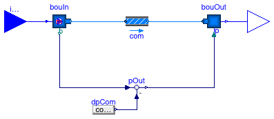
Declaration of an FMU that exports a fixed resistance
Information
This example demonstrates how to export an FMU with a fluid flow component. The FMU has an instance of Buildings.Fluid.FixedResistances.PressureDrop.
Extends from Buildings.Fluid.FMI.ExportContainers.ReplaceableTwoPort (Container to export thermofluid flow models with two ports as an FMU).
Parameters
| Type | Name | Default | Description |
|---|---|---|---|
| replaceable package Medium | PartialMedium | Medium in the component | |
| Boolean | use_p_in | true | = true to use a pressure from connector, false to output Medium.p_default |
| MassFlowRate | m_flow_nominal | 0.01 | Nominal mass flow rate [kg/s] |
| PressureDifference | dp_nominal | 100 | Pressure drop at nominal mass flow rate [Pa] |
| Assumptions | |||
| Boolean | allowFlowReversal | true | = true to allow flow reversal, false restricts to design direction (inlet -> outlet) |
Connectors
| Type | Name | Description |
|---|---|---|
| replaceable package Medium | Medium in the component | |
| Inlet | inlet | Fluid inlet |
| Outlet | outlet | Fluid outlet |
Modelica definition
 Buildings.Fluid.FMI.ExportContainers.Examples.FMUs.ResistanceVolume
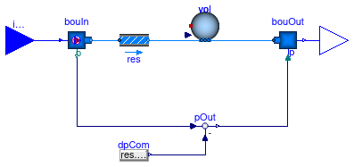
Declaration of an FMU that exports a flow resistance and control volume
Information
This example demonstrates how to export an FMU with a flow resistance and a control volume. The FMU has an instance of Buildings.Fluid.FixedResistances.PressureDrop and Buildings.Fluid.MixingVolumes.MixingVolume.
The mass dynamics has been set to
massDynamics=Modelica.Fluid.Types.Dynamics.SteadyState.
See the
user's guide
for the rationale.
Extends from Buildings.Fluid.FMI.ExportContainers.PartialTwoPort (Partial block to be used as a container to export a thermofluid flow model with two ports).
Parameters
| Type | Name | Default | Description |
|---|---|---|---|
| replaceable package Medium | PartialMedium | Medium in the component | |
| Boolean | use_p_in | true | = true to use a pressure from connector, false to output Medium.p_default |
| Volume | V | 1 | Volume [m3] |
| MassFlowRate | m_flow_nominal | 0.01 | Nominal mass flow rate [kg/s] |
| PressureDifference | dp_nominal | 100 | Nominal pressure drop [Pa] |
| Assumptions | |||
| Boolean | allowFlowReversal | true | = true to allow flow reversal, false restricts to design direction (inlet -> outlet) |
Connectors
| Type | Name | Description |
|---|---|---|
| replaceable package Medium | Medium in the component | |
| Inlet | inlet | Fluid inlet |
| Outlet | outlet | Fluid outlet |
Modelica definition
 Buildings.Fluid.FMI.ExportContainers.Examples.FMUs.ThermalZone
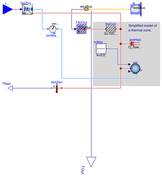
Declaration of an FMU that exports a thermal zone
Information
This example demonstrates how to export a model that contains one thermal zone with convective heat input from the HVAC system only. The thermal zone is connected to an adaptor so that it can be coupled to an air-based HVAC system. The thermal zone is taken from Buildings.Examples.Tutorial.SpaceCooling.System3.
The example extends from
Buildings.Fluid.FMI.ExportContainers.ThermalZone
which provides
the input and output signals that are needed to interface
the acausal thermal zone model with causal connectors of FMI.
The instance theZonAda is the thermal zone adaptor
that contains on the right a fluid port, and on
the left signal ports which are then used to connect at
the top-level of the model to signal ports which are
exposed at the FMU interface.
Extends from Buildings.Fluid.FMI.ExportContainers.ThermalZone (Partial block to export a model of a thermal zone as an FMU).
Parameters
| Type | Name | Default | Description |
|---|---|---|---|
| replaceable package Medium | PartialMedium | Medium in the component | |
| Integer | nPorts | 2 | Number of fluid ports |
| replaceable package MediumA | Buildings.Media.Air | Medium for air | |
| Volume | V | 6*10*3 | Room volume [m3] |
| Temperature | TASup_nominal | 273.15 + 18 | Nominal air temperature supplied to room [K] |
| Temperature | TRooSet | 273.15 + 24 | Nominal room air temperature [K] |
| Temperature | TOut_nominal | 273.15 + 30 | Design outlet air temperature [K] |
| HeatFlowRate | QRooInt_flow | 1000 | Internal heat gains of the room [W] |
| HeatFlowRate | QRooC_flow_nominal | -QRooInt_flow - 10E3/30*(TOu... | Nominal cooling load of the room [W] |
| MassFlowRate | mA_flow_nominal | 1.3*QRooC_flow_nominal/1006/... | Nominal air mass flow rate, increased by factor 1.3 to allow for recovery after temperature setback [kg/s] |
Connectors
| Type | Name | Description |
|---|---|---|
| replaceable package Medium | Medium in the component | |
| Inlet | fluPor[nPorts] | Fluid connector |
| replaceable package MediumA | Medium for air | |
| Bus | weaBus | Weather data bus |
| output RealOutput | TOut | Outdoor temperature [K] |
| output RealOutput | TRad | Radiative temperature [K] |
Modelica definition
 Buildings.Fluid.FMI.ExportContainers.Examples.FMUs.ThermalZones
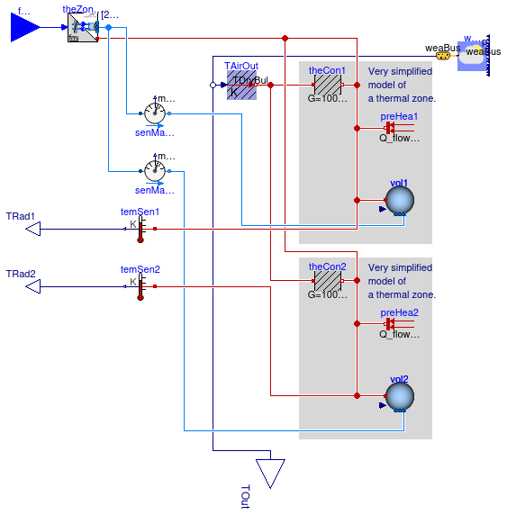
Declaration of an FMU that exports multiple thermal zones
Information
This example demonstrates how to export a model that contains two thermal zones with convective heat input from the HVAC system only. The thermal zones are connected to an adaptor so that they can be coupled to an air-based HVAC system. The thermal zone is taken from Buildings.Examples.Tutorial.SpaceCooling.System3.
The example extends from
Buildings.Fluid.FMI.ExportContainers.ThermalZones
which provides
the input and output signals that are needed to interface
the acausal thermal zone models with causal connectors of FMI.
The instance theZonAda is the thermal zone adaptor
that contains on the right a fluid port, and on
the left signal ports which are then used to connect at
the top-level of the model to signal ports which are
exposed at the FMU interface.
Extends from Buildings.Fluid.FMI.ExportContainers.ThermalZones (Partial block to export a model of multiple thermal zones as an FMU).
Parameters
| Type | Name | Default | Description |
|---|---|---|---|
| replaceable package Medium | PartialMedium | Medium in the component | |
| Integer | nZon | 2 | Number of thermal zones in this container |
| Integer | nPorts | 3 | Number of fluid ports for each zone (must be the same for every zone) |
| replaceable package MediumA | Buildings.Media.Air | Medium for air | |
| Volume | V | 6*10*3 | Room volume [m3] |
| Temperature | TASup_nominal | 273.15 + 18 | Nominal air temperature supplied to room [K] |
| Temperature | TRooSet | 273.15 + 24 | Nominal room air temperature [K] |
| Temperature | TOut_nominal | 273.15 + 30 | Design outlet air temperature [K] |
| HeatFlowRate | QRooInt_flow | 1000 | Internal heat gains of the room [W] |
| HeatFlowRate | QRooC_flow_nominal | -QRooInt_flow - 10E3/30*(TOu... | Nominal cooling load of the room [W] |
| MassFlowRate | mA_flow_nominal | 1.3*QRooC_flow_nominal/1006/... | Nominal air mass flow rate, increased by factor 1.3 to allow for recovery after temperature setback [kg/s] |
Connectors
| Type | Name | Description |
|---|---|---|
| replaceable package Medium | Medium in the component | |
| Inlet | fluPor[nZon, nPorts] | Fluid connectors |
| replaceable package MediumA | Medium for air | |
| Bus | weaBus | Weather data bus |
| output RealOutput | TOut | Outdoor temperature [K] |
| output RealOutput | TRad1 | Radiative temperature [K] |
| output RealOutput | TRad2 | Radiative temperature [K] |
Modelica definition
 Buildings.Fluid.FMI.ExportContainers.Examples.FMUs.TwoPortPassThrough
Declaration of an FMU that exports a block that simply passes all the inputs to the outputs

Information
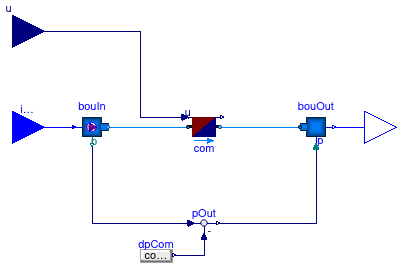
This example demonstrates how to export an FMU that simply passes all its inputs to its outputs. Such an FMU could for example be used in a block diagram as a place-holder for another FMU that provides an actual implementation of a component.
Extends from Buildings.Fluid.FMI.ExportContainers.PartialTwoPort (Partial block to be used as a container to export a thermofluid flow model with two ports).
Parameters
| Type | Name | Default | Description |
|---|---|---|---|
| replaceable package Medium | PartialMedium | Medium in the component | |
| Boolean | use_p_in | true | = true to use a pressure from connector, false to output Medium.p_default |
| Assumptions | |||
| Boolean | allowFlowReversal | true | = true to allow flow reversal, false restricts to design direction (inlet -> outlet) |
Connectors
| Type | Name | Description |
|---|---|---|
| replaceable package Medium | Medium in the component | |
| Inlet | inlet | Fluid inlet |
| Outlet | outlet | Fluid outlet |