Buildings.Fluid.FMI.Adaptors
Package with adaptors to connect models with fluid ports and models with signal ports
Information
This package contains adaptors that allow connecting models with fluid ports and models with input and output signals. These adaptors are used, for example, to export an HVAC system as a Functional Mockup Unit.
Extends from Modelica.Icons.Package (Icon for standard packages).
Package Content
| Name | Description |
|---|---|
| Adaptor for connecting an HVAC system to signal ports which then can be exposed at an FMI interface | |
| Adaptor for connecting a fluid inlet to the FMI interface | |
| Adaptor for connecting a fluid outlet to the FMI interface | |
| Adaptor for connecting a thermal zone to signal ports which then can be exposed at an FMI interface | |
| Collection of models that illustrate model use and test models |
 Buildings.Fluid.FMI.Adaptors.HVAC
Adaptor for connecting an HVAC system to signal ports which then can be exposed at an FMI interface
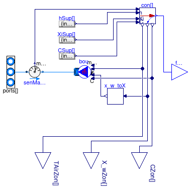
Information
Adaptor that can be used to connect an HVAC system (with acausal ports) to input/output signals, which then can be exposed in an FMI interface.
The adaptor has a vector of fluid ports called ports.
The supply and return air ducts need to be connected to these ports.
Also, if a thermal zone has interzonal air exchange or air infiltration,
these flow paths also need be connected to ports.
This model outputs at the port fluPor the mass flow rate for
each flow that is connected to ports, together with its
temperature, water vapor mass fraction per total mass of the air (not per kg dry
air), and trace substances. These quantities are always as if the flow
enters the room, even if the flow is zero or negative.
If a medium has no moisture, e.g., if Medium.nXi=0, or
if it has no trace substances, e.g., if Medium.nC=0, then
the output signal for these properties are removed.
These quantities are always as if the flow
enters the room, even if the flow is zero or negative.
Thus, a thermal zone model that uses these signals to compute the
heat added by the HVAC system need to implement an equation such as
Qsen = max(0, ṁsup) cp (Tsup - Tair,zon),
where
Qsen is the sensible heat flow rate added to the thermal zone,
ṁsup is the supply air mass flow rate from
the port fluPor (which is negative if it is an exhaust),
cp is the specific heat capacity at constant pressure,
Tsup is the supply air temperature and
Tair,zon is the zone air temperature.
Note that without the max(·, ·) function, the energy
balance would be wrong.
The output signals of this model are the zone air temperature,
the water vapor mass fraction per total mass of the air (unless Medium.nXi=0)
and trace substances (unless Medium.nC=0).
These output connectors can be used to connect to a controller.
These values are obtained from the fluid stream(s) that flow into this component
at the port fluPor, e.g., from the connector
fluPor.backward.
Note that there are nPorts of these signals.
For a completely mixed room, they will all have the same value, but
for a room with non-uniform temperatures, they can have different values.
Assumption and limitations
The mass flow rates at ports sum to zero, hence this
model conserves mass.
This model does not impose any pressure, other than setting the pressure
of all fluid connections to ports to be equal.
The reason is that setting a pressure can lead to non-physical system models,
for example if a mass flow rate is imposed and the HVAC system is connected
to a model that sets a pressure boundary condition such as
Buildings.Fluid.Sources.Outside.
Also, setting a pressure would make it impossible to use multiple instances
of this model (one for each thermal zone) and build in Modelica an airflow network
model with pressure driven mass flow rates.
The model has no pressure drop. Hence, the pressure drop
of an air diffuser or of an exhaust grill need to be modelled
in models that are connected to ports.
Typical use and important parameters
See Buildings.Fluid.FMI.ExportContainers.HVACZone for a model that uses this model.
Parameters
| Type | Name | Default | Description |
|---|---|---|---|
| replaceable package Medium | Modelica.Media.Interfaces.Pa... | Medium in the component | |
| Integer | nPorts | Number of ports | |
Connectors
| Type | Name | Description |
|---|---|---|
| replaceable package Medium | Medium in the component | |
| Outlet | fluPor[nPorts] | Fluid connector |
| FluidPorts_b | ports[nPorts] | |
| output RealOutput | TAirZon[nPorts] | Temperature of the backward flowing medium in the connector outlet [K] |
| output RealOutput | X_wZon[nPorts] | Water mass fraction per total air mass of the backward flowing medium in the connector outlet [kg/kg] |
| output RealOutput | CZon[nPorts, Medium.nC] | Trace substances of the backward flowing medium in the connector outlet |
Modelica definition
 Buildings.Fluid.FMI.Adaptors.Inlet
Adaptor for connecting a fluid inlet to the FMI interface
Information
Model that is used to connect an input signal to a fluid port. The model needs to be used in conjunction with an instance of Buildings.Fluid.FMI.Adaptors.Outlet in order for fluid mass flow rate and pressure to be properly assigned to the acausal fluid models.
See Buildings.Fluid.FMI.ExportContainers.PartialTwoPort or Buildings.Fluid.FMI.ExportContainers.Examples.FMUs.ResistanceVolume for how to use this model.
Parameters
| Type | Name | Default | Description |
|---|---|---|---|
| replaceable package Medium | Modelica.Media.Interfaces.Pa... | Medium in the component | |
| Boolean | use_p_in | true | = true to use a pressure from connector, false to output Medium.p_default |
| Assumptions | |||
| Boolean | allowFlowReversal | true | = true to allow flow reversal, false restricts to design direction (inlet -> outlet) |
Connectors
| Type | Name | Description |
|---|---|---|
| replaceable package Medium | Medium in the component | |
| Inlet | inlet | Fluid inlet |
| FluidPort_b | port_b | Fluid port |
| output PressureOutput | p | Pressure [Pa] |
Modelica definition
 Buildings.Fluid.FMI.Adaptors.Outlet
Adaptor for connecting a fluid outlet to the FMI interface
Information
Model that is used to connect a fluid port with an output signal. The model needs to be used in conjunction with an instance of Buildings.Fluid.FMI.Adaptors.Inlet in order for fluid mass flow rate and pressure to be properly assigned to the acausal fluid models.
See Buildings.Fluid.FMI.ExportContainers.PartialTwoPort or Buildings.Fluid.FMI.ExportContainers.Examples.FMUs.ResistanceVolume for how to use this model.
Parameters
| Type | Name | Default | Description |
|---|---|---|---|
| replaceable package Medium | Modelica.Media.Interfaces.Pa... | Medium in the component | |
| Boolean | use_p_in | true | = true to use a pressure from connector, false to output Medium.p_default |
| Assumptions | |||
| Boolean | allowFlowReversal | true | = true to allow flow reversal, false restricts to design direction (inlet -> outlet) |
Connectors
| Type | Name | Description |
|---|---|---|
| replaceable package Medium | Medium in the component | |
| Outlet | outlet | Fluid outlet |
| FluidPort_a | port_a | Fluid port |
| input PressureInput | p | Pressure to be sent to outlet [Pa] |
Modelica definition
 Buildings.Fluid.FMI.Adaptors.ThermalZone
Adaptor for connecting a thermal zone to signal ports which then can be exposed at an FMI interface
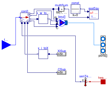
Information
Adaptor that can be used to connect a model of a thermal zone (with acausal ports) to input/output signals, which can be exposed in an FMI interface.
This model has a vector fluPor with dimension nPorts
which can be exposed at the FMI interface for the connecting the HVAC system.
These connectors contain for each fluid inlet the mass flow rate, the temperature,
the water vapor mass fraction per total mass of the air (unless Medium.nXi=0),
and the trace substances (unless Medium.nC=0).
The connector ports can be used to connect the model with a thermal zone.
The number of connections to ports must
be equal to nPorts.
Assumption and limitations
The mass flow rates at ports sum to zero, hence this
model conserves mass. If the mass flow rates at fluPor
do not sum to zero, then this model stops with an error.
This model does not impose any pressure, other than setting the pressure
of all fluid connections to ports to be equal.
The reason is that setting a pressure can lead to non-physical system models,
for example if a mass flow rate is imposed and the HVAC system is connected
to a model that sets a pressure boundary condition such as
Buildings.Fluid.Sources.Outside.
Also, setting a pressure would make it impossible to use multiple instances
of this model (one for each thermal zone) and build in Modelica an airflow network
model with pressure driven mass flow rates.
The model has no pressure drop.
Typical use
See Buildings.Fluid.FMI.ExportContainers.ThermalZone for a model that uses this model.
Parameters
| Type | Name | Default | Description |
|---|---|---|---|
| replaceable package Medium | Modelica.Media.Interfaces.Pa... | Medium in the component | |
| Integer | nPorts | Number of fluid ports | |
Connectors
| Type | Name | Description |
|---|---|---|
| replaceable package Medium | Medium in the component | |
| Inlet | fluPor[nPorts] | Fluid connector |
| FluidPorts_b | ports[nPorts] | |
| HeatPort_a | heaPorAir | Heat port for sensible heat input |
Modelica definition
 Buildings.Fluid.FMI.Adaptors.HVAC.RealVectorExpression
Set vector output signal to a time varying vector Real expression

Information
The (time varying) vector Real output signal of this block can be defined in its
parameter menu via variable y. The purpose is to support the
easy definition of vector-valued Real expressions in a block diagram.
Parameters
| Type | Name | Default | Description |
|---|---|---|---|
| Integer | n | Dimension of output signal | |
| Time varying output signal | |||
| RealOutput | y[n] | Value of Real output | |
Connectors
| Type | Name | Description |
|---|---|---|
| Time varying output signal | ||
| output RealOutput | y[n] | Value of Real output |
Modelica definition
 Buildings.Fluid.FMI.Adaptors.ThermalZone.x_i_toX_w
Conversion from Xi to X
Information
Extends from Modelica.Blocks.Icons.Block (Basic graphical layout of input/output block).
Parameters
| Type | Name | Default | Description |
|---|---|---|---|
| replaceable package Medium | Modelica.Media.Interfaces.Pa... | Medium model within the source | |
Connectors
| Type | Name | Description |
|---|---|---|
| replaceable package Medium | Medium model within the source | |
| input RealInput | Xi[Medium.nXi] | Water vapor concentration in kg/kg total air [kg/kg] |
| output RealOutput | X_w | Water vapor concentration in kg/kg total air [kg/kg] |
Modelica definition
Buildings.Fluid.FMI.Adaptors.ThermalZone.RealVectorExpression
Set vector output signal to a time varying vector Real expression
Information
The (time varying) vector Real output signal of this block can be defined in its
parameter menu via variable y. The purpose is to support the
easy definition of vector-valued Real expressions in a block diagram.
Parameters
| Type | Name | Default | Description |
|---|---|---|---|
| Integer | n | Dimension of output signal | |
| Time varying output signal | |||
| RealOutput | y[n] | Value of Real output | |
Connectors
| Type | Name | Description |
|---|---|---|
| Time varying output signal | ||
| output RealOutput | y[n] | Value of Real output |