Buildings.Electrical.DC.Sources.Examples
Package with example models
Information
This package contains examples for the use of models that can be found in Buildings.Electrical.DC.Sources.
Extends from Modelica.Icons.ExamplesPackage (Icon for packages containing runnable examples).
Package Content
| Name | Description |
|---|---|
| Example for the PVSimple model with constant load | |
| Example for the PVSimpleOriented model with constant load | |
| Example for the variable voltage source model | |
| Example for the WindTurbine model |
 Buildings.Electrical.DC.Sources.Examples.PVSimple
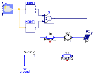
Example for the PVSimple model with constant load
Information
This model illustrates the use of the photovoltaic model. The total solar irradiation is computed based on a weather data file. The PV is connected to a circuit that has a constant voltage source and a resistance. This voltage source may be a DC grid to which the circuit is connected. The power sensor shows how much electrical power is consumed or fed into the voltage source. In actual systems, the voltage source may be an AC/DC converter.
Extends from Modelica.Icons.Example (Icon for runnable examples).
Modelica definition
Buildings.Electrical.DC.Sources.Examples.PVSimpleOriented
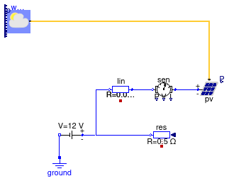
Example for the PVSimpleOriented model with constant load
Information
This model illustrates the use of the photovoltaic model. The total solar irradiation is computed internally by the PV model through a connection to the weather bus. The PV is connected to a circuit that has a constant voltage source and a resistance. This voltage source may be a DC grid to which the circuit is connected. The power sensor shows how much electrical power is consumed or fed into the voltage source. In actual systems, the voltage source may be an AC/DC converter.
Extends from Modelica.Icons.Example (Icon for runnable examples).
Modelica definition
Buildings.Electrical.DC.Sources.Examples.VoltageSource
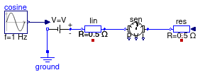
Example for the variable voltage source model
Information
This model illustrates the use of the variable voltage source model.
Extends from Modelica.Icons.Example (Icon for runnable examples).
Modelica definition
 Buildings.Electrical.DC.Sources.Examples.WindTurbine
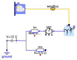
Example for the WindTurbine model
Information
This model illustrates the use of the wind turbine model which is connected to a DC voltage source and a resistance. This voltage source may be a DC grid to which the circuit is connected. Wind data for San Francisco, CA, are used. The turbine cut-in wind speed is 3.5 m/s, and hence it is off in the first day when the wind speed is low.
Extends from Modelica.Icons.Example (Icon for runnable examples).
Connectors
| Type | Name | Description |
|---|---|---|
| Bus | weaBus |