Buildings.Electrical.AC.ThreePhasesUnbalanced.Validation.IEEETests.Test4NodesFeeder.UnbalancedStepUp
Package that contains the examples for unbalanced loads and step up transformer
Information
This package contains examples for the IEEE 4 nodes test validation whith unbalanced load and step up in the voltage of the transformers.
Extends from Modelica.Icons.ExamplesPackage (Icon for packages containing runnable examples).
Package Content
| Name | Description |
|---|---|
| IEEE 4 node test feeder model with unbalanced load and D - D connection (step up) | |
| IEEE 4 node test feeder model with unbalanced load and D - Y connection (step up) | |
| IEEE 4 node test feeder model with unbalanced load and Y - D connection (step up) | |
| IEEE 4 node test feeder model with unbalanced load and Y - Y connection (step up) |
 Buildings.Electrical.AC.ThreePhasesUnbalanced.Validation.IEEETests.Test4NodesFeeder.UnbalancedStepUp.DD
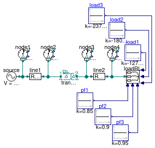
IEEE 4 node test feeder model with unbalanced load and D - D connection (step up)
Information
IEEE 4 nodes validation test case with the following characteristics
- balanced load,
- power consumption on phases P1 = 2375 kW, P2 = 1800 kW, and P3 = 1275 kW
- power factor on phases cosφ1 = 0.85, cosφ2 = 0.9, and cosφ3 = 0.95
- voltage step-up transformer (VPri=12.47 kV, VSec = 24.9kV),
- D-D transformer
Extends from Buildings.Electrical.AC.ThreePhasesUnbalanced.Validation.IEEETests.Test4NodesFeeder.BaseClasses.IEEE4 (Base model of the IEEE 4 nodes test feeder).
Parameters
| Type | Name | Default | Description |
|---|---|---|---|
| Voltage | VLL_side1 | 12.47e3 | Voltage line to line side 1 [V] |
| Voltage | VLL_side2 | 24.9e3 | Voltage line to line side 2 [V] |
| ApparentPower | VARbase | 6000e3 | Base VA power of the transformer [V.A] |
| Boolean | line1_use_Z_y | false | Choose between Zy or Zd impedance matrix for line 1 |
| Boolean | line2_use_Z_y | false | Choose between Zy or Zd impedance matrix for line 2 |
| Voltage | V2_ref[3] | {12362,12392,12334} | Reference RMS voltage node 2 - IEEE results [V] |
| Voltage | V3_ref[3] | {23675,24060,23573} | Reference RMS voltage node 3 - IEEE results [V] |
| Voltage | V4_ref[3] | {23610,24015,23492} | Reference RMS voltage node 4 - IEEE results [V] |
| Angle | Theta2_ref[3] | Modelica.Constants.pi/180.0*... | Reference voltage phase angle node 2 - IEEE results [rad] |
| Angle | Theta3_ref[3] | Modelica.Constants.pi/180.0*... | Reference voltage phase angle node 3 - IEEE results [rad] |
| Angle | Theta4_ref[3] | Modelica.Constants.pi/180.0*... | Reference voltage phase angle node 4 - IEEE results [rad] |
Modelica definition
Buildings.Electrical.AC.ThreePhasesUnbalanced.Validation.IEEETests.Test4NodesFeeder.UnbalancedStepUp.DY
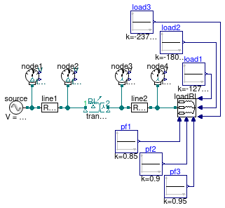
IEEE 4 node test feeder model with unbalanced load and D - Y connection (step up)
Information
IEEE 4 nodes validation test case with the following characteristics
- balanced load,
- power consumption on phases P1 = 2375 kW, P2 = 1800 kW, and P3 = 1275 kW
- power factor on phases cosφ1 = 0.85, cosφ2 = 0.9, and cosφ3 = 0.95
- voltage step-up transformer (VPri=12.47 kV, VSec = 24.9kV),
- D-Y transformer
Extends from Buildings.Electrical.AC.ThreePhasesUnbalanced.Validation.IEEETests.Test4NodesFeeder.BaseClasses.IEEE4 (Base model of the IEEE 4 nodes test feeder).
Parameters
| Type | Name | Default | Description |
|---|---|---|---|
| Voltage | VLL_side1 | 12.47e3 | Voltage line to line side 1 [V] |
| Voltage | VLL_side2 | 24.9e3 | Voltage line to line side 2 [V] |
| ApparentPower | VARbase | 6000e3 | Base VA power of the transformer [V.A] |
| Boolean | line1_use_Z_y | false | Choose between Zy or Zd impedance matrix for line 1 |
| Boolean | line2_use_Z_y | true | Choose between Zy or Zd impedance matrix for line 2 |
| Voltage | V2_ref[3] | {12364,12391,12333} | Reference RMS voltage node 2 - IEEE results [V] |
| Voltage | V3_ref[3] | {13792,13733,13641} | Reference RMS voltage node 3 - IEEE results [V] |
| Voltage | V4_ref[3] | {13768,13684,13600} | Reference RMS voltage node 4 - IEEE results [V] |
| Angle | Theta2_ref[3] | Modelica.Constants.pi/180.0*... | Reference voltage phase angle node 2 - IEEE results [rad] |
| Angle | Theta3_ref[3] | Modelica.Constants.pi/180.0*... | Reference voltage phase angle node 3 - IEEE results [rad] |
| Angle | Theta4_ref[3] | Modelica.Constants.pi/180.0*... | Reference voltage phase angle node 4 - IEEE results [rad] |
Modelica definition
Buildings.Electrical.AC.ThreePhasesUnbalanced.Validation.IEEETests.Test4NodesFeeder.UnbalancedStepUp.YD
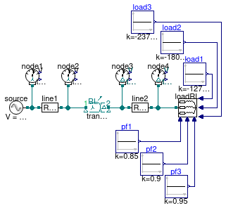
IEEE 4 node test feeder model with unbalanced load and Y - D connection (step up)
Information
IEEE 4 nodes validation test case with the following characteristics
- balanced load,
- power consumption on phases P1 = 2375 kW, P2 = 1800 kW, and P3 = 1275 kW
- power factor on phases cosφ1 = 0.85, cosφ2 = 0.9, and cosφ3 = 0.95
- voltage step-up transformer (VPri=12.47 kV, VSec = 24.9kV),
- Y-D transformer
Extends from Buildings.Electrical.AC.ThreePhasesUnbalanced.Validation.IEEETests.Test4NodesFeeder.BaseClasses.IEEE4 (Base model of the IEEE 4 nodes test feeder).
Parameters
| Type | Name | Default | Description |
|---|---|---|---|
| Voltage | VLL_side1 | 12.47e3 | Voltage line to line side 1 [V] |
| Voltage | VLL_side2 | 24.9e3 | Voltage line to line side 2 [V] |
| ApparentPower | VARbase | 6000e3 | Base VA power of the transformer [V.A] |
| Boolean | line1_use_Z_y | true | Choose between Zy or Zd impedance matrix for line 1 |
| Boolean | line2_use_Z_y | false | Choose between Zy or Zd impedance matrix for line 2 |
| Voltage | V2_ref[3] | {7121,7147,7150} | Reference RMS voltage node 2 - IEEE results [V] |
| Voltage | V3_ref[3] | {23703,24040,23576} | Reference RMS voltage node 3 - IEEE results [V] |
| Voltage | V4_ref[3] | {23637,23995,23496} | Reference RMS voltage node 4 - IEEE results [V] |
| Angle | Theta2_ref[3] | Modelica.Constants.pi/180.0*... | Reference voltage phase angle node 2 - IEEE results [rad] |
| Angle | Theta3_ref[3] | Modelica.Constants.pi/180.0*... | Reference voltage phase angle node 3 - IEEE results [rad] |
| Angle | Theta4_ref[3] | Modelica.Constants.pi/180.0*... | Reference voltage phase angle node 4 - IEEE results [rad] |
Modelica definition
Buildings.Electrical.AC.ThreePhasesUnbalanced.Validation.IEEETests.Test4NodesFeeder.UnbalancedStepUp.YY
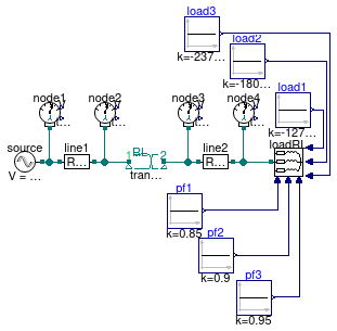
IEEE 4 node test feeder model with unbalanced load and Y - Y connection (step up)
Information
IEEE 4 nodes validation test case with the following characteristics
- balanced load,
- power consumption on phases P1 = 2375 kW, P2 = 1800 kW, and P3 = 1275 kW
- power factor on phases cosφ1 = 0.85, cosφ2 = 0.9, and cosφ3 = 0.95
- voltage step-up transformer (VPri=12.47 kV, VSec = 24.9kV),
- Y-Y transformer
Extends from Buildings.Electrical.AC.ThreePhasesUnbalanced.Validation.IEEETests.Test4NodesFeeder.BaseClasses.IEEE4 (Base model of the IEEE 4 nodes test feeder).
Parameters
| Type | Name | Default | Description |
|---|---|---|---|
| Voltage | VLL_side1 | 12.47e3 | Voltage line to line side 1 [V] |
| Voltage | VLL_side2 | 24.9e3 | Voltage line to line side 2 [V] |
| ApparentPower | VARbase | 6000e3 | Base VA power of the transformer [V.A] |
| Boolean | line1_use_Z_y | true | Choose between Zy or Zd impedance matrix for line 1 |
| Boolean | line2_use_Z_y | true | Choose between Zy or Zd impedance matrix for line 2 |
| Voltage | V2_ref[3] | {7161,7120,7128} | Reference RMS voltage node 2 - IEEE results [V] |
| Voltage | V3_ref[3] | {13839,13663,13655} | Reference RMS voltage node 3 - IEEE results [V] |
| Voltage | V4_ref[3] | {13815,13614,13615} | Reference RMS voltage node 4 - IEEE results [V] |
| Angle | Theta2_ref[3] | Modelica.Constants.pi/180.0*... | Reference voltage phase angle node 2 - IEEE results [rad] |
| Angle | Theta3_ref[3] | Modelica.Constants.pi/180.0*... | Reference voltage phase angle node 3 - IEEE results [rad] |
| Angle | Theta4_ref[3] | Modelica.Constants.pi/180.0*... | Reference voltage phase angle node 4 - IEEE results [rad] |