Buildings.Electrical.AC.ThreePhasesUnbalanced.Conversion
Package with converter and transformer models for three-phase unbalanced AC systems
Information
This package contains models that represent different types of three phases unbalanced AC/AC transformers and AC/DC converters.
Extends from Modelica.Icons.Package (Icon for standard packages).
Package Content
| Name | Description |
|---|---|
| AC AC converter single phase systems (YY) | |
| AC AC transformer simplified equivalent circuit (YY) | |
| AC AC transformer simplified equivalent circuit (DD) | |
| AC AC transformer detailed equivalent circuit (YY) | |
| AC AC transformer simplified equivalent circuit (DY step down) | |
| AC AC transformer simplified equivalent circuit (YD step down) | |
| AC AC transformer simplified equivalent circuit (DY step up) | |
| AC AC transformer simplified equivalent circuit (YD step up) | |
| Package with example models | |
| Package with base class models |
 Buildings.Electrical.AC.ThreePhasesUnbalanced.Conversion.ACACConverter
AC AC converter single phase systems (YY)
Information
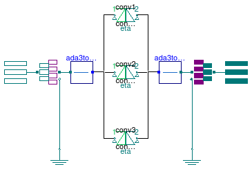
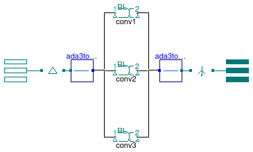
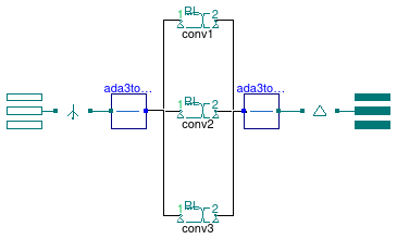
This is an AC AC converter, based on a power balance between both circuit sides. The parameter conversionFactor defines the ratio between the RMS voltages
V2 = conversionFactor * V1
where V1 and V2 are the RMS voltages at the primary and secondary sides of the transformer (connector N and P respectively).
The loss of the converter is proportional to the power transmitted.
The parameter eta is the efficiency of the transfer.
The loss is computed as
Ploss = (1-η) Ptr
where Ptr is the power transmitted. The model is bi-directional and the power can flow from both the primary to the secondary and vice-versa. Furthermore, reactive power on both side are set to 0.
Configuration:
The image below describes the connection of the windings.
Note:
This model reuses models from Buildings.Electrical.AC.OnePhase.Conversion.ACACConverter.
See Buildings.Electrical.AC.ThreePhasesUnbalanced.Conversion.BaseClasses.PartialConverterYY for details on the connections.
Extends from Buildings.Electrical.AC.ThreePhasesUnbalanced.Conversion.BaseClasses.PartialConverterYY (Model of a transformer with Y connection primary side and Y connection secondary side).
Parameters
| Type | Name | Default | Description |
|---|---|---|---|
| Real | conversionFactor | Ratio of QS rms voltage on side 2 / QS rms voltage on side 1 | |
| Efficiency | eta | Converter efficiency, pLoss = (1-eta) * Ptr [1] | |
| Ground | |||
| side 1 | |||
| Boolean | ground_1 | false | Connect side 1 of converter to ground |
| side 2 | |||
| Boolean | ground_2 | true | Connect side 2 of converter to ground |
Connectors
| Type | Name | Description |
|---|---|---|
| Terminal_n | terminal_n | Electrical connector side N |
| Terminal_p | terminal_p | Electrical connector side P |
Modelica definition
 Buildings.Electrical.AC.ThreePhasesUnbalanced.Conversion.ACACTransformer
AC AC transformer simplified equivalent circuit (YY)
Information
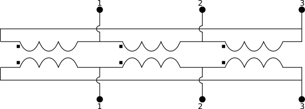
This is a simplified equivalent transformer model. The model accounts for winding Joule losses and leakage reactances that are represented by a series of a resistance R and an inductance L. The resistance and the inductance represent both the effects of the secondary and primary side of the transformer.
The model is parameterized using the following parameters
Vhigh- RMS voltage at primary side,Vlow- RMS voltage at secondary side,VAbase- apparent nominal power of the transformer,XoverR- ratio between reactance and resistance, andZperc- the short circuit impedance.
Given the nominal conditions, the model computes the values of the resistance and inductance.
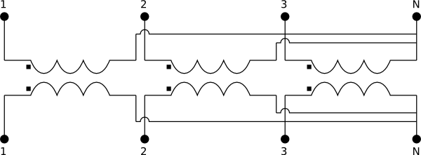
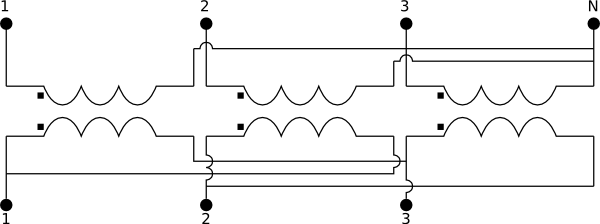
Configuration:
The image below describes the connection of the windings.
Note:
This model reuses models from Buildings.Electrical.AC.OnePhase.Conversion.ACACTransformer.
See Buildings.Electrical.AC.ThreePhasesUnbalanced.Conversion.BaseClasses.PartialConverterYY for details on the connections.
Extends from Buildings.Electrical.AC.ThreePhasesUnbalanced.Conversion.BaseClasses.PartialConverterYY (Model of a transformer with Y connection primary side and Y connection secondary side).
Parameters
| Type | Name | Default | Description |
|---|---|---|---|
| Voltage | VHigh | Rms voltage on side 1 of the transformer (primary side) [V] | |
| Voltage | VLow | Rms voltage on side 2 of the transformer (secondary side) [V] | |
| ApparentPower | VABase | Nominal power of the transformer [V.A] | |
| Real | XoverR | Ratio between the complex and real components of the impedance (XL/R) | |
| Real | Zperc | Short circuit impedance | |
| Ground | |||
| side 1 | |||
| Boolean | ground_1 | false | Connect side 1 of transformer to ground |
| side 2 | |||
| Boolean | ground_2 | true | Connect side 2 of transformer to ground |
Connectors
| Type | Name | Description |
|---|---|---|
| Terminal_n | terminal_n | Electrical connector side N |
| Terminal_p | terminal_p | Electrical connector side P |
Modelica definition
 Buildings.Electrical.AC.ThreePhasesUnbalanced.Conversion.ACACTransformerDD
AC AC transformer simplified equivalent circuit (DD)
Information
This is a simplified equivalent transformer model with Delta-Delta connection. The model accounts for winding Joule losses and leakage reactances that are represented by a series of a resistance R and an inductance L. The resistance and the inductance represent the effects of the secondary and primary side of the transformer.
The model is parameterized using the following parameters
Vhigh- RMS voltage at primary side,Vlow- RMS voltage at secondary side,VAbase- apparent nominal power of the transformer,XoverR- ratio between reactance and resistance, andZperc- the short circuit impedance.
Given the nominal conditions, the model computes the values of the resistance and inductance.
Configuration:
The image below describes the connection of the windings.
Note:
This model reuses models from Buildings.Electrical.AC.OnePhase.Conversion.ACACTransformer.
See Buildings.Electrical.AC.ThreePhasesUnbalanced.Conversion.BaseClasses.PartialConverterDD for details on the connections.
Extends from Buildings.Electrical.AC.ThreePhasesUnbalanced.Conversion.BaseClasses.PartialConverterDD (Model of a transformer with D connection primary side and D connection secondary side).
Parameters
| Type | Name | Default | Description |
|---|---|---|---|
| Voltage | VHigh | Rms voltage on side 1 of the transformer (primary side) [V] | |
| Voltage | VLow | Rms voltage on side 2 of the transformer (secondary side) [V] | |
| ApparentPower | VABase | Nominal power of the transformer [V.A] | |
| Real | XoverR | Ratio between the complex and real components of the impedance (XL/R) | |
| Real | Zperc | Short circuit impedance | |
| Ground | |||
| side 1 | |||
| Boolean | ground_1 | false | Connect side 1 of transformer to ground |
| side 2 | |||
| Boolean | ground_2 | true | Connect side 2 of transformer to ground |
Connectors
| Type | Name | Description |
|---|---|---|
| Terminal_n | terminal_n | Electrical connector side N |
| Terminal_p | terminal_p | Electrical connector side P |
Modelica definition
Buildings.Electrical.AC.ThreePhasesUnbalanced.Conversion.ACACTransformerFull
AC AC transformer detailed equivalent circuit (YY)

Information
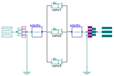
This is a detailed transformer model that takes into accounts the winding Joule losses, and the leakage reactances on the primary and secondary side. The model also takes into account the core or iron losses and the losses due to magnetization effects.
The losses are represented by a series of resistances R1, R2, Rm and inductances L1, L2, and Lm.
The model is parameterized using the following parameters
Vhigh- RMS voltage at primary side,Vlow- RMS voltage at secondary side,VAbase- apparent nominal power of the transformer,f- frequency,R_1, L_1- resistance and inductance at primary side (per unit),R_2, L_2- resistance and inductance at secondary side (per unit), andR_m, L_m- resistance and inductance for magnetization effects (per unit).
Given the nominal conditions, the model computes the values of the nominal impedances at the primary and secondary side. Given these values, the per unit values are transformed into the actual values of the resistances and inductancs.
The magnetization losses can be enabled or disabled using the boolean flag magEffects.
Configuration:
The image below describes the connection of the windings.
Note:
This model reuses models from Buildings.Electrical.AC.OnePhase.Conversion.ACACTransformerFull.
See Buildings.Electrical.AC.ThreePhasesUnbalanced.Conversion.BaseClasses.PartialConverterYY for details on the connections.
Extends from Buildings.Electrical.AC.ThreePhasesUnbalanced.Conversion.BaseClasses.PartialConverterYY (Model of a transformer with Y connection primary side and Y connection secondary side).
Parameters
| Type | Name | Default | Description |
|---|---|---|---|
| Voltage | VHigh | Rms voltage on side 1 of the transformer (primary side) [V] | |
| Voltage | VLow | Rms voltage on side 2 of the transformer (secondary side) [V] | |
| ApparentPower | VABase | Nominal power of the transformer [V.A] | |
| Frequency | f | Nominal frequency [Hz] | |
| PerUnit | R1 | Resistance on side 1 of the transformer (pu) [1] | |
| PerUnit | L1 | Inductance on side 1 of the transformer (pu) [1] | |
| PerUnit | R2 | Resistance on side 2 of the transformer (pu) [1] | |
| PerUnit | L2 | Inductance on side 2 of the transformer (pu) [1] | |
| Magnetization | |||
| Boolean | magEffects | false | If =true introduce magnetization effects |
| PerUnit | Rm | Magnetization resistance (pu) [1] | |
| PerUnit | Lm | Magnetization inductance (pu) [1] | |
| Ground | |||
| side 1 | |||
| Boolean | ground_1 | false | Connect side 1 of converter to ground |
| side 2 | |||
| Boolean | ground_2 | true | Connect side 2 of converter to ground |
Connectors
| Type | Name | Description |
|---|---|---|
| Terminal_n | terminal_n | Electrical connector side N |
| Terminal_p | terminal_p | Electrical connector side P |
Modelica definition
 Buildings.Electrical.AC.ThreePhasesUnbalanced.Conversion.ACACTransformerStepDownDY
AC AC transformer simplified equivalent circuit (DY step down)

Information
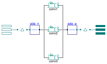
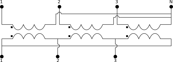
This is a simplified equivalent transformer model with Y-Delta connection (voltage step down). The model accounts for winding Joule losses and leakage reactances that are represented by a series of a resistance R and an inductance L. The resistance and the inductance represent the effects of the secondary and primary side of the transformer.
The model is parameterized using the following parameters
Vhigh- RMS voltage at primary side,Vlow- RMS voltage at secondary side,VAbase- apparent nominal power of the transformer,XoverR- ratio between reactance and resistance, andZperc- the short circuit impedance.
Given the nominal conditions, the model computes the values of the resistance and inductance.
Configuration:
The image below describes the connection of the windings.

Note:
This model reuses models from Buildings.Electrical.AC.OnePhase.Conversion.ACACTransformer.
See Buildings.Electrical.AC.ThreePhasesUnbalanced.Conversion.BaseClasses.PartialConverterStepDownDY for details on the connections.
Extends from Buildings.Electrical.AC.ThreePhasesUnbalanced.Conversion.BaseClasses.PartialConverterStepDownDY (Model of a transformer with D connection primary side and Y connection secondary side (Voltage step down)).
Parameters
| Type | Name | Default | Description |
|---|---|---|---|
| Voltage | VHigh | Rms voltage on side 1 of the transformer (primary side) [V] | |
| Voltage | VLow | Rms voltage on side 2 of the transformer (secondary side) [V] | |
| ApparentPower | VABase | Nominal power of the transformer [V.A] | |
| Real | XoverR | Ratio between the complex and real components of the impedance (XL/R) | |
| Real | Zperc | Short circuit impedance | |
| Ground | |||
| side 1 | |||
| Boolean | ground_1 | false | Connect side 1 of transformer to ground |
| side 2 | |||
| Boolean | ground_2 | true | Connect side 2 of transformer to ground |
Connectors
| Type | Name | Description |
|---|---|---|
| Terminal_n | terminal_n | Electrical connector side N |
| Terminal_p | terminal_p | Electrical connector side P |
Modelica definition
 Buildings.Electrical.AC.ThreePhasesUnbalanced.Conversion.ACACTransformerStepDownYD
AC AC transformer simplified equivalent circuit (YD step down)

Information
This is a simplified equivalent transformer model with Y-Delta connection (voltage step down). The model accounts for winding Joule losses and leakage reactances that are represented by a series of a resistance R and an inductance L. The resistance and the inductance represent the effects of the secondary and primary side of the transformer.
The model is parameterized using the following parameters
Vhigh- RMS voltage at primary side,Vlow- RMS voltage at secondary side,VAbase- apparent nominal power of the transformer,XoverR- ratio between reactance and resistance, andZperc- the short circuit impedance.
Given the nominal conditions, the model computes the values of the resistance and inductance.
Configuration:
The image below describes the connection of the windings.
Note:
This model reuses models from Buildings.Electrical.AC.OnePhase.Conversion.ACACTransformer.
See Buildings.Electrical.AC.ThreePhasesUnbalanced.Conversion.BaseClasses.PartialConverterStepDownYD for details on the connections.
Extends from Buildings.Electrical.AC.ThreePhasesUnbalanced.Conversion.BaseClasses.PartialConverterStepDownYD (Model of a transformer with Y connection primary side and D connection secondary side (Voltage step down)).
Parameters
| Type | Name | Default | Description |
|---|---|---|---|
| Voltage | VHigh | Rms voltage on side 1 of the transformer (primary side) [V] | |
| Voltage | VLow | Rms voltage on side 2 of the transformer (secondary side) [V] | |
| ApparentPower | VABase | Nominal power of the transformer [V.A] | |
| Real | XoverR | Ratio between the complex and real components of the impedance (XL/R) | |
| Real | Zperc | Short circuit impedance | |
| Ground | |||
| side 1 | |||
| Boolean | ground_1 | false | Connect side 1 of transformer to ground |
| side 2 | |||
| Boolean | ground_2 | true | Connect side 2 of transformer to ground |
Connectors
| Type | Name | Description |
|---|---|---|
| Terminal_n | terminal_n | Electrical connector side N |
| Terminal_p | terminal_p | Electrical connector side P |
Modelica definition
 Buildings.Electrical.AC.ThreePhasesUnbalanced.Conversion.ACACTransformerStepUpDY
AC AC transformer simplified equivalent circuit (DY step up)
Information
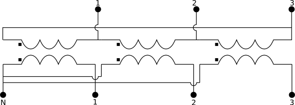
This is a simplified equivalent transformer model with Delta-Y connection (voltage step up). The model accounts for winding Joule losses and leakage reactances that are represented by a series of a resistance R and an inductance L. The resistance and the inductance represent the effects of the secondary and primary side of the transformer.
The model is parameterized using the following parameters
Vhigh- RMS voltage at primary side,Vlow- RMS voltage at secondary side,VAbase- apparent nominal power of the transformer,XoverR- ratio between reactance and resistance, andZperc- the short circuit impedance.
Given the nominal conditions, the model computes the values of the resistance and inductance.
Configuration:
The image below describes the connection of the windings.
Note:
This model reuses models from Buildings.Electrical.AC.OnePhase.Conversion.ACACTransformer.
See Buildings.Electrical.AC.ThreePhasesUnbalanced.Conversion.BaseClasses.PartialConverterStepUpDY for details on the connections.
Extends from Buildings.Electrical.AC.ThreePhasesUnbalanced.Conversion.BaseClasses.PartialConverterStepUpDY (Model of a transformer with D connection primary side and Y connection secondary side (Voltage step up)).
Parameters
| Type | Name | Default | Description |
|---|---|---|---|
| Voltage | VHigh | Rms voltage on side 1 of the transformer (primary side) [V] | |
| Voltage | VLow | Rms voltage on side 2 of the transformer (secondary side) [V] | |
| ApparentPower | VABase | Nominal power of the transformer [V.A] | |
| Real | XoverR | Ratio between the complex and real components of the impedance (XL/R) | |
| Real | Zperc | Short circuit impedance | |
| Ground | |||
| side 1 | |||
| Boolean | ground_1 | false | Connect side 1 of transformer to ground |
| side 2 | |||
| Boolean | ground_2 | true | Connect side 2 of transformer to ground |
Connectors
| Type | Name | Description |
|---|---|---|
| Terminal_n | terminal_n | Electrical connector side N |
| Terminal_p | terminal_p | Electrical connector side P |
Modelica definition
 Buildings.Electrical.AC.ThreePhasesUnbalanced.Conversion.ACACTransformerStepUpYD
AC AC transformer simplified equivalent circuit (YD step up)
Information
This is a simplified equivalent transformer model with Y-Delta connection (voltage step up). The model accounts for winding Joule losses and leakage reactances that are represented by a series of a resistance R and an inductance L. The resistance and the inductance represent the effects of the secondary and primary side of the transformer.
The model is parameterized using the following parameters
Vhigh- RMS voltage at primary side,Vlow- RMS voltage at secondary side,VAbase- apparent nominal power of the transformer,XoverR- ratio between reactance and resistance, andZperc- the short circuit impedance.
Given the nominal conditions, the model computes the values of the resistance and inductance.
Configuration:
The image below describes the connection of the windings.
Note:
This model reuses models from Buildings.Electrical.AC.OnePhase.Conversion.ACACTransformer.
See Buildings.Electrical.AC.ThreePhasesUnbalanced.Conversion.BaseClasses.PartialConverterStepUpYD for details on the connections.
Extends from Buildings.Electrical.AC.ThreePhasesUnbalanced.Conversion.BaseClasses.PartialConverterStepUpYD (Model of a transformer with Y connection primary side and D connection secondary side (Voltage step up)).
Parameters
| Type | Name | Default | Description |
|---|---|---|---|
| Voltage | VHigh | Rms voltage on side 1 of the transformer (primary side) [V] | |
| Voltage | VLow | Rms voltage on side 2 of the transformer (secondary side) [V] | |
| ApparentPower | VABase | Nominal power of the transformer [V.A] | |
| Real | XoverR | Ratio between the complex and real components of the impedance (XL/R) | |
| Real | Zperc | Short circuit impedance | |
| Ground | |||
| side 1 | |||
| Boolean | ground_1 | false | Connect side 1 of transformer to ground |
| side 2 | |||
| Boolean | ground_2 | true | Connect side 2 of transformer to ground |
Connectors
| Type | Name | Description |
|---|---|---|
| Terminal_n | terminal_n | Electrical connector side N |
| Terminal_p | terminal_p | Electrical connector side P |