Buildings.Electrical.AC.ThreePhasesUnbalanced.Validation.IEEETests.Test4NodesFeeder.BalancedStepDown
Package that contains the examples for balanced loads and step down transformer
Information
This package contains examples for the IEEE 4 nodes test validation whith balanced load and step down in the voltage of the transformers.
Extends from Modelica.Icons.ExamplesPackage (Icon for packages containing runnable examples).
Package Content
| Name | Description |
|---|---|
| IEEE 4 node test feeder model with balanced load and D - D connection (step down) | |
| IEEE 4 node test feeder model with balanced load and D - Y connection (step down) | |
| IEEE 4 node test feeder model with balanced load and Y - D connection (step down) | |
| IEEE 4 node test feeder model with balanced load and Y - Y connection (step down) |
 Buildings.Electrical.AC.ThreePhasesUnbalanced.Validation.IEEETests.Test4NodesFeeder.BalancedStepDown.DD
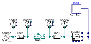
IEEE 4 node test feeder model with balanced load and D - D connection (step down)
Information
IEEE 4 nodes validation test case with the following characteristics
- balanced load,
- power consumption on each phase P1,2,3 = 1800 kW
- power factor on each phase cosφ1,2,3 = 0.9
- voltage step-down transformer (VPri=12.47 kV, VSec = 4.16kV),
- D-D transformer
Extends from Buildings.Electrical.AC.ThreePhasesUnbalanced.Validation.IEEETests.Test4NodesFeeder.BaseClasses.IEEE4 (Base model of the IEEE 4 nodes test feeder).
Parameters
| Type | Name | Default | Description |
|---|---|---|---|
| Voltage | VLL_side1 | 12.47e3 | Voltage line to line side 1 [V] |
| Voltage | VLL_side2 | 4.16e3 | Voltage line to line side 2 [V] |
| ApparentPower | VARbase | 6000e3 | Base VA power of the transformer [V.A] |
| Boolean | line1_use_Z_y | false | Choose between Zy or Zd impedance matrix for line 1 |
| Boolean | line2_use_Z_y | false | Choose between Zy or Zd impedance matrix for line 2 |
| Voltage | V2_ref[3] | {12339,12349,12321} | Reference RMS voltage node 2 - IEEE results [V] |
| Voltage | V3_ref[3] | {3911,3914,3905} | Reference RMS voltage node 3 - IEEE results [V] |
| Voltage | V4_ref[3] | {3442,3497,3384} | Reference RMS voltage node 4 - IEEE results [V] |
| Angle | Theta2_ref[3] | Modelica.Constants.pi/180.0*... | Reference voltage phase angle node 2 - IEEE results [rad] |
| Angle | Theta3_ref[3] | Modelica.Constants.pi/180.0*... | Reference voltage phase angle node 3 - IEEE results [rad] |
| Angle | Theta4_ref[3] | Modelica.Constants.pi/180.0*... | Reference voltage phase angle node 4 - IEEE results [rad] |
Modelica definition
Buildings.Electrical.AC.ThreePhasesUnbalanced.Validation.IEEETests.Test4NodesFeeder.BalancedStepDown.DY
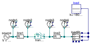
IEEE 4 node test feeder model with balanced load and D - Y connection (step down)
Information
IEEE 4 nodes validation test case with the following characteristics
- balanced load,
- power consumption on each phase P1,2,3 = 1800 kW
- power factor on each phase cosφ1,2,3 = 0.9
- voltage step-down transformer (VPri=12.47 kV, VSec = 4.16kV),
- D-Y transformer
Extends from Buildings.Electrical.AC.ThreePhasesUnbalanced.Validation.IEEETests.Test4NodesFeeder.BaseClasses.IEEE4 (Base model of the IEEE 4 nodes test feeder).
Parameters
| Type | Name | Default | Description |
|---|---|---|---|
| Voltage | VLL_side1 | 12.47e3 | Voltage line to line side 1 [V] |
| Voltage | VLL_side2 | 4.16e3 | Voltage line to line side 2 [V] |
| ApparentPower | VARbase | 6000e3 | Base VA power of the transformer [V.A] |
| Boolean | line1_use_Z_y | false | Choose between Zy or Zd impedance matrix for line 1 |
| Boolean | line2_use_Z_y | true | Choose between Zy or Zd impedance matrix for line 2 |
| Voltage | V2_ref[3] | {12340,12349,12318} | Reference RMS voltage node 2 - IEEE results [V] |
| Voltage | V3_ref[3] | {2249,2263,2259} | Reference RMS voltage node 3 - IEEE results [V] |
| Voltage | V4_ref[3] | {1920,2054,1986} | Reference RMS voltage node 4 - IEEE results [V] |
| Angle | Theta2_ref[3] | Modelica.Constants.pi/180.0*... | Reference voltage phase angle node 2 - IEEE results [rad] |
| Angle | Theta3_ref[3] | Modelica.Constants.pi/180.0*... | Reference voltage phase angle node 3 - IEEE results [rad] |
| Angle | Theta4_ref[3] | Modelica.Constants.pi/180.0*... | Reference voltage phase angle node 4 - IEEE results [rad] |
Modelica definition
Buildings.Electrical.AC.ThreePhasesUnbalanced.Validation.IEEETests.Test4NodesFeeder.BalancedStepDown.YD
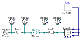
IEEE 4 node test feeder model with balanced load and Y - D connection (step down)
Information
IEEE 4 nodes validation test case with the following characteristics
- balanced load,
- power consumption on each phase P1,2,3 = 1800 kW
- power factor on each phase cosφ1,2,3 = 0.9
- voltage step-down transformer (VPri=12.47 kV, VSec = 4.16kV),
- Y-D transformer
Extends from Buildings.Electrical.AC.ThreePhasesUnbalanced.Validation.IEEETests.Test4NodesFeeder.BaseClasses.IEEE4 (Base model of the IEEE 4 nodes test feeder).
Parameters
| Type | Name | Default | Description |
|---|---|---|---|
| Voltage | VLL_side1 | 12.47e3 | Voltage line to line side 1 [V] |
| Voltage | VLL_side2 | 4.16e3 | Voltage line to line side 2 [V] |
| ApparentPower | VARbase | 6000e3 | Base VA power of the transformer [V.A] |
| Boolean | line1_use_Z_y | true | Choose between Zy or Zd impedance matrix for line 1 |
| Boolean | line2_use_Z_y | false | Choose between Zy or Zd impedance matrix for line 2 |
| Voltage | V2_ref[3] | {7113,7132,7123} | Reference RMS voltage node 2 - IEEE results [V] |
| Voltage | V3_ref[3] | {3906,3915,3909} | Reference RMS voltage node 3 - IEEE results [V] |
| Voltage | V4_ref[3] | {3437,3497,3388} | Reference RMS voltage node 4 - IEEE results [V] |
| Angle | Theta2_ref[3] | Modelica.Constants.pi/180.0*... | Reference voltage phase angle node 2 - IEEE results [rad] |
| Angle | Theta3_ref[3] | Modelica.Constants.pi/180.0*... | Reference voltage phase angle node 3 - IEEE results [rad] |
| Angle | Theta4_ref[3] | Modelica.Constants.pi/180.0*... | Reference voltage phase angle node 4 - IEEE results [rad] |
Modelica definition
Buildings.Electrical.AC.ThreePhasesUnbalanced.Validation.IEEETests.Test4NodesFeeder.BalancedStepDown.YY
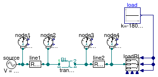
IEEE 4 node test feeder model with balanced load and Y - Y connection (step down)
Information
IEEE 4 nodes validation test case with the following characteristics
- balanced load,
- power consumption on each phase P1,2,3 = 1800 kW
- power factor on each phase cosφ1,2,3 = 0.9
- voltage step-down transformer (VPri=12.47 kV, VSec = 4.16kV),
- Y-Y transformer
Extends from Buildings.Electrical.AC.ThreePhasesUnbalanced.Validation.IEEETests.Test4NodesFeeder.BaseClasses.IEEE4 (Base model of the IEEE 4 nodes test feeder).
Parameters
| Type | Name | Default | Description |
|---|---|---|---|
| Voltage | VLL_side1 | 12.47e3 | Voltage line to line side 1 [V] |
| Voltage | VLL_side2 | 4.16e3 | Voltage line to line side 2 [V] |
| ApparentPower | VARbase | 6000e3 | Base VA power of the transformer [V.A] |
| Boolean | line1_use_Z_y | true | Choose between Zy or Zd impedance matrix for line 1 |
| Boolean | line2_use_Z_y | true | Choose between Zy or Zd impedance matrix for line 2 |
| Voltage | V2_ref[3] | {7107,7140,7121} | Reference RMS voltage node 2 - IEEE results [V] |
| Voltage | V3_ref[3] | {2247,2269,2256} | Reference RMS voltage node 3 - IEEE results [V] |
| Voltage | V4_ref[3] | {1918,2061,1981} | Reference RMS voltage node 4 - IEEE results [V] |
| Angle | Theta2_ref[3] | Modelica.Constants.pi/180.0*... | Reference voltage phase angle node 2 - IEEE results [rad] |
| Angle | Theta3_ref[3] | Modelica.Constants.pi/180.0*... | Reference voltage phase angle node 3 - IEEE results [rad] |
| Angle | Theta4_ref[3] | Modelica.Constants.pi/180.0*... | Reference voltage phase angle node 4 - IEEE results [rad] |