Buildings.Electrical.AC.ThreePhasesUnbalanced.Lines.Examples
Package with example models
Information
This package contains examples for the use of models that can be found in Buildings.Electrical.AC.ThreePhasesUnbalanced.Lines.
Extends from Modelica.Icons.ExamplesPackage (Icon for packages containing runnable examples).
Package Content
| Name | Description |
|---|---|
| Test model for a three-phase unbalanced commercial cable without neutral | |
| Test model for a three-phase unbalanced inductive-resistive line specified by a Z matrix | |
| Test model for a three-phase unbalanced RLC line specified by Z and B matrices | |
| Test model for a three-phase unbalanced RLC line with neutral cable specified by Z and B matrices | |
| Test model for a three-phase unbalanced inductive-resistive line with neutral cable specified by a Z matrix | |
| Test model for a three-phase unbalanced inductive line | |
| Test model for a three-phase unbalanced inductive line with neutral cable | |
| Test model for a three-phase unbalanced commercial cable with neutral | |
| Test model for a three-phase unbalanced resistive line | |
| Test model for a three-phase unbalanced inductive-resistive line | |
| Test model for a three-phase unbalanced RLC line | |
| Test model for a three-phase unbalanced RLC line with neutral cable | |
| Test model for a three-phase unbalanced inductive-resistive line with neutral cable | |
| Test model for a three-phase unbalanced resistive line with neutral cable | |
| Test model for a network model for three-phase unbalanced systems without neutral cable | |
| Test model for a network model for three-phase unbalanced systems with neutral cable |
 Buildings.Electrical.AC.ThreePhasesUnbalanced.Lines.Examples.ACLine
Test model for a three-phase unbalanced commercial cable without neutral
Information
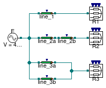
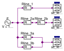
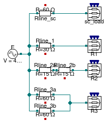
This example demonstrates how to use a cable model without neutral line to connect a source to a load.
The model has three resistive loads R1, R2, and R3.
Each load is connected to the source with different configurations,
but the equivalent resistance between each load and the source is the same.
Since the equivalent resistances are the same, each load draws the same current.
Extends from Modelica.Icons.Example (Icon for runnable examples).
Modelica definition
Buildings.Electrical.AC.ThreePhasesUnbalanced.Lines.Examples.ACLineMatrix_RL
Test model for a three-phase unbalanced inductive-resistive line specified by a Z matrix
Information
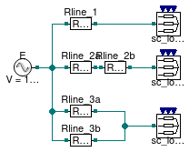
This example demonstrates how to use an inductive resistive line model to connect a source to a load. The model is parameterized using the impedance matrix Z.
The model has three loads. The loads represent a short circuit R=0. The current that flows through the load depends on the resistance of the line.
Extends from Modelica.Icons.Example (Icon for runnable examples).
Modelica definition
Buildings.Electrical.AC.ThreePhasesUnbalanced.Lines.Examples.ACLineMatrix_RLC
Test model for a three-phase unbalanced RLC line specified by Z and B matrices
Information
This example demonstrates how to use a RLC line model to connect a source to a load. The model is parameterized using the impedance matrix Z and the admittance matrix B.
The example shows two configurations to test a zero and non-zero matrix B. In the second case the impedance matrix Z has been set to zero. Therefore, the line model does not have a load connected to it.
Extends from Modelica.Icons.Example (Icon for runnable examples).
Modelica definition
Buildings.Electrical.AC.ThreePhasesUnbalanced.Lines.Examples.ACLineMatrix_RLC_N
Test model for a three-phase unbalanced RLC line with neutral cable specified by Z and B matrices
Information
This example demonstrates how to use a RLC line model with neutral line to connect a source to a load. The model is parameterized using the impedance matrix Z and the admittance matrix B.
The example shows two configurations to test a zero and non-zero matrix B. In the second case the impedance matrix Z has been set to zero. Therefore, the line model does not have a load connected to it.
Extends from Modelica.Icons.Example (Icon for runnable examples).
Modelica definition
Buildings.Electrical.AC.ThreePhasesUnbalanced.Lines.Examples.ACLineMatrix_RL_N
Test model for a three-phase unbalanced inductive-resistive line with neutral cable specified by a Z matrix
Information
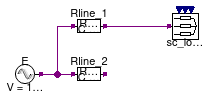
This example demonstrates how to use an inductive resistive line model with neutral line to connect a source to a load. The model is parameterized using the impedance matrix Z.
The model has three loads. The loads represent a short circuit R=0. The current that flows through the load depends on the resistance of the line.
Extends from Modelica.Icons.Example (Icon for runnable examples).
Modelica definition
Buildings.Electrical.AC.ThreePhasesUnbalanced.Lines.Examples.ACLine_L
Test model for a three-phase unbalanced inductive line
Information
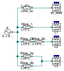
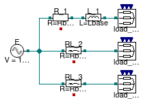
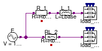
This example demonstrates how to use a purely inductive line model to connect a source to a load.
The model has four different loads. The load sc_load represents
a short circuit R=0. The current that flows through the load depends
on the resistance of the line.
The remaining three loads L1, L2, and L3
are inductive loads. Each load is connected to the source with different configurations,
but the equivalent impedance between each load and the source is the same.
Since the equivalent impedances are the same, each load draws the same current.
Extends from Modelica.Icons.Example (Icon for runnable examples).
Parameters
| Type | Name | Default | Description |
|---|---|---|---|
| Inductance | Lbase | 10/2/Modelica.Constants.pi/60 | Base value for the line inductances [H] |
Modelica definition
Buildings.Electrical.AC.ThreePhasesUnbalanced.Lines.Examples.ACLine_L_N
Test model for a three-phase unbalanced inductive line with neutral cable
Information
This example demonstrates how to use a purely inductive line model with neutral cable to connect a source to a load.
The model has four different loads. The load sc_load represents
a short circuit R=0. The current that flows through the load depends
on the resistance of the line.
The remaining three loads L1, L2, and L3
are inductive loads. Each load is connected to the source with different configurations,
but the equivalent impedance between each load and the source is the same.
Since the equivalent impedances are the same, each load draws the same current.
Extends from Modelica.Icons.Example (Icon for runnable examples).
Parameters
| Type | Name | Default | Description |
|---|---|---|---|
| Inductance | Lbase | 10/2/Modelica.Constants.pi/60 | Base value for the line inductances [H] |
Modelica definition
Buildings.Electrical.AC.ThreePhasesUnbalanced.Lines.Examples.ACLine_N
Test model for a three-phase unbalanced commercial cable with neutral
Information
This example demonstrates how to use a cable line model with neutral to connect a source to a load.
The model has three resistive loads R1, R2, and R3.
Each load is connected to the source with different configurations,
but the equivalent resistance between each load and the source is the same.
Since the equivalent resistances are the same, each load draws the same current.
Extends from Modelica.Icons.Example (Icon for runnable examples).
Modelica definition
Buildings.Electrical.AC.ThreePhasesUnbalanced.Lines.Examples.ACLine_R
Test model for a three-phase unbalanced resistive line
Information
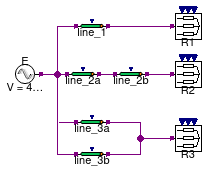
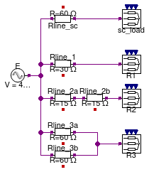
This example demonstrates how to use a resistive line model to connect a source to a load.
The model has four different loads. The load sc_load represents
a short circuit R=0. The current that flows through the load depends
on the resistance of the line.
The remaining three loads R1, R2, and R3
are resistive loads. Each load is connected to the source with different configurations,
but the equivalent resistance between each load and the source is the same.
Since the equivalent resistances are the same, each load draws the same current.
Extends from Modelica.Icons.Example (Icon for runnable examples).
Modelica definition
Buildings.Electrical.AC.ThreePhasesUnbalanced.Lines.Examples.ACLine_RL
Test model for a three-phase unbalanced inductive-resistive line
Information
This example demonstrates how to use a resistive-inductive line model to connect a source to a load.
The model has three loads load_sc_1, load_sc_2,
and load_sc_3 representing short circuits R=0.
The current that flows through the load depends on the impedance of the line.
Each load is connected to the source with different configurations, but the equivalent impedance between each load and the source is the same. Since the equivalent impedances are the same, each load draw the same current.
Note:
The line model RL_3 is the same as RL_2 but it uses
dynamic phasors.
Extends from Modelica.Icons.Example (Icon for runnable examples).
Parameters
| Type | Name | Default | Description |
|---|---|---|---|
| Resistance | Rbase | 3*10 | Base value for the line resistance [Ohm] |
| Inductance | Lbase | Rbase/2/Modelica.Constants.p... | Base value for the line inductance [H] |
Modelica definition
Buildings.Electrical.AC.ThreePhasesUnbalanced.Lines.Examples.ACLine_RLC
Test model for a three-phase unbalanced RLC line
Information
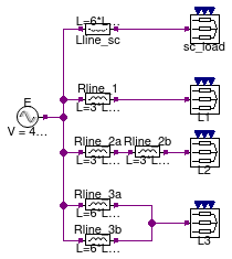
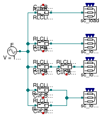
This example demonstrates how to use an RLC line model to connect a source to a load.
The model has four different loads. The loads sc_load,
sc_load1, sc_load2, sc_load3 represent
short circuits R=0. The current that flows through the load depends
on the resistance, inductance and capacitance of the line.
The parameter R, L and C are such that at the nominal frequency fnom = 60 Hz the respective resistance and reactances are all equal to 10 Ω.
The lines used in this example have a T model (see Buildings.Electrical.AC.ThreePhasesUnbalanced.Lines.TwoPortRLC). The equivalent impedance of the line on each phase is equal to
ZEQ = R/2 +jXL/2 + (R/2 +jXL/2)(-jXC)/ (R/2 +jXL/2 -jXC)
that in this case is equal to ZEQ = 15 + j5 Ω.
Given the equivalent impedance of each phase, and a voltage with an RMS value of 100 V produces a current equal to I = 6 - j2 A flowing through phase 1.
Notes
(1) Note:
The line model RLCLine_sc is the same as RLCLine_1 but it uses
dynamic phasors.
(2) Note:
The line model RLCLine_2a has a current that is different
from the one passing in RLCLine_1 because the series of two T
line models is different from the sum of the two separate line models.
(3) Note:
The line models RLCLine_3a and RLCLine_3b have currents that are
50% of the other lines because they are in parallel.
Extends from Modelica.Icons.Example (Icon for runnable examples).
Parameters
| Type | Name | Default | Description |
|---|---|---|---|
| Resistance | RBase | 3*10 | Base value for the line resistance [Ohm] |
| Inductance | LBase | RBase/(2*Modelica.Constants.... | Base value for the line inductances [H] |
| Capacitance | CBase | 3*0.1/(2*Modelica.Constants.... | Base value for the line inductances [F] |
Modelica definition
Buildings.Electrical.AC.ThreePhasesUnbalanced.Lines.Examples.ACLine_RLC_N
Test model for a three-phase unbalanced RLC line with neutral cable
Information
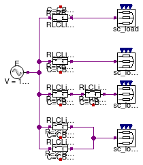
This example demonstrates how to use an RLC line model with neutral cable to connect a source to a load.
The model has four different loads. The loads sc_load,
sc_load1, sc_load2, sc_load3 represent
short circuits R=0. The current that flows through the load depends
on the resistance, inductance and capacitance of the line.
The parameter R, L and C are such that at the nominal frequency fnom = 60 Hz the respective resistance and reactances are all equal to 10 Ω.
The lines used in this example have a T model (see Buildings.Electrical.AC.ThreePhasesUnbalanced.Lines.TwoPortRLC). The equivalent impedance of the line on each phase is equal to
ZEQ = R/2 +jXL/2 + (R/2 +jXL/2)(-jXC)/ (R/2 +jXL/2 -jXC)
that in this case is equal to ZEQ = 15 + j5 Ω.
Given the equivalent impedance of each phase, and a voltage with an RMS value of 100 V produces a current equal to I = 6 - j2 A flowing through phase 1.
Notes
(1) Note:
The line model RLCLine_sc is the same as RLCLine_1 but it uses
dynamic phasors.
(2) Note:
The line model RLCLine_2a has a current that is different
from the one passing in RLCLine_1 because the series of two T
line models is different from the sum of the two separate line models.
(3) Note:
The line models RLCLine_3a and RLCLine_3b have currents that are
50% of the other lines because they are in parallel.
Extends from Modelica.Icons.Example (Icon for runnable examples).
Parameters
| Type | Name | Default | Description |
|---|---|---|---|
| Resistance | RBase | 3*10 | Base value for the line resistance [Ohm] |
| Inductance | LBase | RBase/(2*Modelica.Constants.... | Base value for the line inductances [H] |
| Capacitance | CBase | 3*0.1/(2*Modelica.Constants.... | Base value for the line inductances [F] |
Modelica definition
Buildings.Electrical.AC.ThreePhasesUnbalanced.Lines.Examples.ACLine_RL_N
Test model for a three-phase unbalanced inductive-resistive line with neutral cable
Information
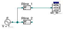
This example demonstrates how to use a resistive-inductive line model with neutral cable to connect a source to a load.
The model has two loads load_sc_1 and load_sc_2
representing short circuits R=0.
The current that flows through the load depends on the impedance of the line.
Each load is connected to the source with different configurations, but the equivalent impedance between each load and the source is the same. Since the equivalent impedances are the same, each load draw the same current.
Extends from Modelica.Icons.Example (Icon for runnable examples).
Parameters
| Type | Name | Default | Description |
|---|---|---|---|
| Resistance | Rbase | 3*10 | Base value for the line resistance [Ohm] |
| Inductance | Lbase | Rbase/2/Modelica.Constants.p... | Base value for the line inductance [H] |
Modelica definition
Buildings.Electrical.AC.ThreePhasesUnbalanced.Lines.Examples.ACLine_R_N
Test model for a three-phase unbalanced resistive line with neutral cable
Information
This example demonstrates how to use a resistive line model with neutral cable to connect a source to a load.
The model has four different loads. The load sc_load represents
a short circuit R=0. The current that flows through the load depends
on the resistance of the line.
The remaining three loads R1, R2, and R3
are resistive loads. Each load is connected to the source with different configurations,
but the equivalent resistance between each load and the source is the same.
Since the equivalent resistances are the same, each load draws the same current.
Extends from Modelica.Icons.Example (Icon for runnable examples).
Modelica definition
Buildings.Electrical.AC.ThreePhasesUnbalanced.Lines.Examples.ACSimpleGrid
Test model for a network model for three-phase unbalanced systems without neutral cable
Information
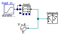
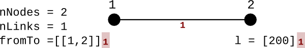
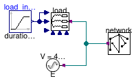
This example demonstrates how to use a network model to connect a source to a load. In this simple case the network has two nodes that are connected by a commercial cable without a neutral line.
At the beginning of the simulation, the load consumes power while at the and it produces power. The voltage at the load at the beginning is lower than the nominal RMS voltage (480 V), while at the end of the simulation it is higher. The voltage drop and increase are due to the presence of the cable between the source and the load.
The network uses cables of the type LowVoltageCable.Cu35 with
a length of 200 m.
The picture below describes the grid topology.
Extends from Modelica.Icons.Example (Icon for runnable examples).
Modelica definition
Buildings.Electrical.AC.ThreePhasesUnbalanced.Lines.Examples.ACSimpleGrid_N
Test model for a network model for three-phase unbalanced systems with neutral cable
Information
This example demonstrates how to use a network model to connect a source to a load. In this simple case the network has two nodes that are connected by a commercial cable with neutral line.
At the beginning of the simulation the load consumes power while at the and it produces power. The voltage at the load at the beginning is lower than the nominal RMS voltage (480 V) while at the end of the simulation it is higher. The voltage drop and increase are due to the presence of the cable between the source and the load.
The network uses cables of the type LowVoltageCable.Cu35 with
a length of 200 m.
The picture below describes the grid topology.
Extends from Modelica.Icons.Example (Icon for runnable examples).