Package with transmission line models for three-phase unbalanced AC systems
Information
This package contains models for transmission lines and electrical networks
of AC three-phase unbalanced systems.
Extends from Modelica.Icons.Package (Icon for standard packages).
Package Content
| Name |
Description |
 Line Line
|
Model of an electrical line without neutral cable |
 Line_N Line_N
|
Model of an electrical line with neutral cable |
 Network Network
|
Three phases unbalanced AC network without neutral cable |
 Network_N Network_N
|
Three phases unbalanced AC network with neutral cable |
 TwoPortInductance TwoPortInductance
|
Model of an inductance with two electrical ports |
 TwoPortInductance_N TwoPortInductance_N
|
Model of an inductance with two electrical ports and neutral line cable |
 TwoPortMatrixRL TwoPortMatrixRL
|
Model of an RL line parameterized with impedance matrices |
| TwoPortMatrixRLC
|
PI model of a line parameterized with impedance and admittance matrices |
 TwoPortMatrixRLC_N TwoPortMatrixRLC_N
|
PI model of a line parameterized with impedance and admittance matrices and neutral line |
| TwoPortMatrixRL_N
|
Model of an RL line parameterized with impedance matrices and neutral line |
 TwoPortRL TwoPortRL
|
Model of a resistive-inductive element with two electrical ports |
 TwoPortRLC TwoPortRLC
|
Model of an RLC element with two electrical ports |
 TwoPortRLC_N TwoPortRLC_N
|
Model of an RLC element with two electrical ports and neutral line cable |
 TwoPortRL_N TwoPortRL_N
|
Model of a resistive-inductive element with two electrical ports and neutral line cable |
 TwoPortResistance TwoPortResistance
|
Model of a resistance with two electrical ports |
 TwoPortResistance_N TwoPortResistance_N
|
Model of a resistance with two electrical ports and neutral cable |
 Examples Examples
|
Package with example models |
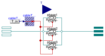
Model of an electrical line without neutral cable
Information
This model represents an AC three-phase unbalanced cable without
neutral connection. The model is based on
Buildings.Electrical.AC.ThreePhasesUnbalanced.Lines.TwoPortRLC
and provides functionalities to parametrize the values of R, L and C
using either commercial cables or default values.
Extends from Buildings.Electrical.AC.ThreePhasesUnbalanced.Interfaces.TwoPort (Partial model interface for a two port component without neutral cable), Buildings.Electrical.Transmission.BaseClasses.PartialBaseLine (Partial cable line dispersion model).
Parameters
| Type | Name | Default | Description |
|---|
| Length | l | | Length of the line [m] |
| Power | P_nominal | | Nominal power of the line [W] |
| Model |
| Assumptions |
| Boolean | use_C | false | Set to true to add a capacitance in the center of the line |
| Load | modelMode | Buildings.Electrical.Types.L... | Select between steady state and dynamic model |
| Thermal |
| Boolean | use_T | false | If true, enables the input for the temperature of the cable |
| Temperature | TCable | T_ref | Fixed temperature of the cable [K] |
| Tech. specification |
| Auto/Manual mode |
| CableMode | mode | Buildings.Electrical.Types.C... | Select if choosing the cable automatically or between a list of commercial options |
| Manual mode |
| Generic | commercialCable | Buildings.Electrical.Transmi... | Commercial cables options |
Connectors
| Type | Name | Description |
|---|
| input RealInput | T | Temperature of the cable |
Modelica definition
model Line
extends Buildings.Electrical.AC.ThreePhasesUnbalanced.Interfaces.TwoPort(
terminal_p(phase(v(
each nominal = V_nominal))),
terminal_n(phase(v(
each nominal = V_nominal))));
extends Buildings.Electrical.Transmission.BaseClasses.PartialBaseLine(
V_nominal(start = 480),
commercialCable =
Buildings.Electrical.Transmission.Functions.selectCable_low(P_nominal, V_nominal));
OnePhase.Lines.TwoPortRL phase1(
final useHeatPort=true,
final T_ref=T_ref,
final M=M,
final R=R/3,
final L=L/3,
final mode=modelMode) ;
OnePhase.Lines.TwoPortRL phase2(
final useHeatPort=true,
final T_ref=T_ref,
final M=M,
final R=R/3,
final L=L/3,
final mode=modelMode) ;
OnePhase.Lines.TwoPortRL phase3(
final useHeatPort=true,
final T_ref=T_ref,
final M=M,
final R=R/3,
final L=L/3,
final mode=modelMode) ;
equation
connect(cableTemp.port, phase1.heatPort);
connect(cableTemp.port, phase2.heatPort);
connect(cableTemp.port, phase3.heatPort);
connect(terminal_n.phase[1], phase1.terminal_n);
connect(terminal_n.phase[2], phase2.terminal_n);
connect(terminal_n.phase[3], phase3.terminal_n);
connect(phase1.terminal_p, terminal_p.phase[1]);
connect(phase2.terminal_p, terminal_p.phase[2]);
connect(phase3.terminal_p, terminal_p.phase[3]);
end Line;
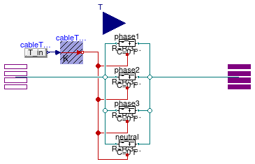
Model of an electrical line with neutral cable
Information
This model represents an AC three-phase unbalanced cable with
neutral connection. The model is based on
Buildings.Electrical.AC.ThreePhasesUnbalanced.Lines.TwoPortRLC
and provides functionalities to parametrize the values of R, L and C
using either commercial cables or default values.
Extends from Buildings.Electrical.AC.ThreePhasesUnbalanced.Interfaces.TwoPort_N (Partial model interface for a two port component with neutral cable), Buildings.Electrical.Transmission.BaseClasses.PartialBaseLine (Partial cable line dispersion model).
Parameters
| Type | Name | Default | Description |
|---|
| Length | l | | Length of the line [m] |
| Power | P_nominal | | Nominal power of the line [W] |
| Model |
| Assumptions |
| Boolean | use_C | false | Set to true to add a capacitance in the center of the line |
| Load | modelMode | Buildings.Electrical.Types.L... | Select between steady state and dynamic model |
| Thermal |
| Boolean | use_T | false | If true, enables the input for the temperature of the cable |
| Temperature | TCable | T_ref | Fixed temperature of the cable [K] |
| Tech. specification |
| Auto/Manual mode |
| CableMode | mode | Buildings.Electrical.Types.C... | Select if choosing the cable automatically or between a list of commercial options |
| Manual mode |
| Generic | commercialCable | Buildings.Electrical.Transmi... | Commercial cables options |
Connectors
| Type | Name | Description |
|---|
| input RealInput | T | Temperature of the cable |
Modelica definition
model Line_N
extends Buildings.Electrical.AC.ThreePhasesUnbalanced.Interfaces.TwoPort_N(
terminal_p(phase(v(
each nominal = V_nominal))),
terminal_n(phase(v(
each nominal = V_nominal))));
extends Buildings.Electrical.Transmission.BaseClasses.PartialBaseLine(
V_nominal(start = 480),
commercialCable =
Buildings.Electrical.Transmission.Functions.selectCable_low(P_nominal, V_nominal));
OnePhase.Lines.TwoPortRL phase1(
final useHeatPort=true,
final T_ref=T_ref,
final M=M,
final mode=modelMode,
final R=R/3,
final L=L/3) ;
OnePhase.Lines.TwoPortRL phase2(
final useHeatPort=true,
final T_ref=T_ref,
final M=M,
final mode=modelMode,
final R=R/3,
final L=L/3) ;
OnePhase.Lines.TwoPortRL phase3(
final useHeatPort=true,
final T_ref=T_ref,
final M=M,
final mode=modelMode,
final R=R/3,
final L=L/3) ;
OnePhase.Lines.TwoPortRL neutral(
final useHeatPort=true,
final T_ref=T_ref,
final M=M,
final mode=modelMode,
final R=R/3,
final L=L/3) ;
equation
connect(cableTemp.port, phase1.heatPort);
connect(cableTemp.port, phase2.heatPort);
connect(cableTemp.port, phase3.heatPort);
connect(terminal_n.phase[1], phase1.terminal_n);
connect(terminal_n.phase[2], phase2.terminal_n);
connect(terminal_n.phase[3], phase3.terminal_n);
connect(phase1.terminal_p, terminal_p.phase[1]);
connect(phase2.terminal_p, terminal_p.phase[2]);
connect(phase3.terminal_p, terminal_p.phase[3]);
connect(cableTemp.port, neutral.heatPort);
connect(terminal_n.phase[4], neutral.terminal_n);
connect(terminal_p.phase[4], neutral.terminal_p);
end Line_N;
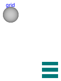
Three phases unbalanced AC network without neutral cable
Information
This model represents a generalized electrical AC three-phase unbalanced network
without neutral cable.
See
Buildings.Electrical.Transmission.BaseClasses.PartialNetwork
for information about the network model.
See
Buildings.Electrical.Transmission.Grids.PartialGrid
for more information about the topology of the network, such as
the number of nodes, how they are connected, and the length of each connection.
Extends from Transmission.BaseClasses.PartialNetwork (Partial model that represent an electric network).
Parameters
| Type | Name | Default | Description |
|---|
| Voltage | V_nominal | | Nominal voltage of the lines in the network [V] |
Modelica definition
model Network
extends Transmission.BaseClasses.PartialNetwork(
redeclare Buildings.Electrical.AC.ThreePhasesUnbalanced.Interfaces.Terminal_p
terminal,
redeclare replaceable Transmission.Grids.TestGrid2Nodes grid,
redeclare Buildings.Electrical.AC.ThreePhasesUnbalanced.Lines.Line lines(commercialCable=grid.cables));
Modelica.Units.SI.Voltage VAbs[3,grid.nNodes] ;
equation
for i
in 1:grid.nLinks
loop
connect(lines[i].terminal_p, terminal[grid.fromTo[i,1]]);
connect(lines[i].terminal_n, terminal[grid.fromTo[i,2]]);
end for;
for i
in 1:grid.nNodes
loop
VAbs[1,i] =
Buildings.Electrical.PhaseSystems.OnePhase.systemVoltage(terminal[i].phase[1].v);
VAbs[2,i] =
Buildings.Electrical.PhaseSystems.OnePhase.systemVoltage(terminal[i].phase[2].v);
VAbs[3,i] =
Buildings.Electrical.PhaseSystems.OnePhase.systemVoltage(terminal[i].phase[3].v);
end for;
end Network;
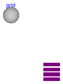
Three phases unbalanced AC network with neutral cable
Information
This model represents a generalized electrical AC three-phase unbalanced network
with neutral cable.
See
Buildings.Electrical.Transmission.BaseClasses.PartialNetwork
for information about the network model.
See
Buildings.Electrical.Transmission.Grids.PartialGrid
for more information about the topology of the network, such as
the number of nodes, how they are connected, and the length of each connection.
Extends from Transmission.BaseClasses.PartialNetwork (Partial model that represent an electric network).
Parameters
| Type | Name | Default | Description |
|---|
| Voltage | V_nominal | | Nominal voltage of the lines in the network [V] |
Modelica definition
model Network_N
extends Transmission.BaseClasses.PartialNetwork(
redeclare Buildings.Electrical.AC.ThreePhasesUnbalanced.Interfaces.Terminal4_p
terminal,
redeclare replaceable Transmission.Grids.TestGrid2Nodes grid,
redeclare Buildings.Electrical.AC.ThreePhasesUnbalanced.Lines.Line_N lines(
commercialCable=grid.cables));
Modelica.Units.SI.Voltage VAbs[3,grid.nNodes] ;
equation
for i
in 1:grid.nLinks
loop
connect(lines[i].terminal_p, terminal[grid.fromTo[i,1]]);
connect(lines[i].terminal_n, terminal[grid.fromTo[i,2]]);
end for;
for i
in 1:grid.nNodes
loop
VAbs[1,i] =
Buildings.Electrical.PhaseSystems.OnePhase.systemVoltage(terminal[i].phase[1].v - terminal[i].phase[4].v);
VAbs[2,i] =
Buildings.Electrical.PhaseSystems.OnePhase.systemVoltage(terminal[i].phase[2].v - terminal[i].phase[4].v);
VAbs[3,i] =
Buildings.Electrical.PhaseSystems.OnePhase.systemVoltage(terminal[i].phase[3].v - terminal[i].phase[4].v);
end for;
end Network_N;
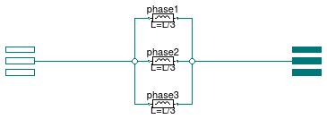
Model of an inductance with two electrical ports
Information
Inductive model that connects two AC three-phase
unbalanced interfaces. This model can be used to represent a
cable in a three-phase unbalanced AC system.
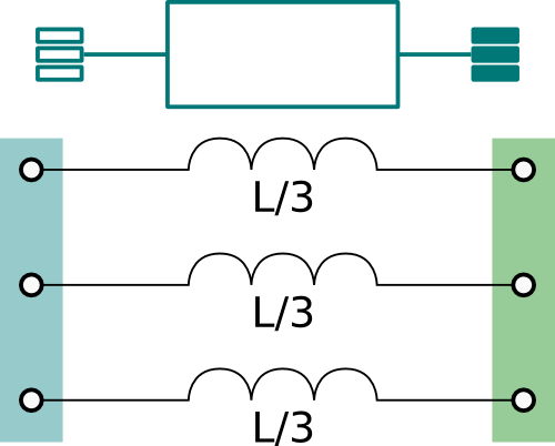
The model represents the lumped inductances as shown in the figure above.
Assuming that the inductance L is the overall inductance of the cable,
each line has an inductance equal to L/3.
Extends from Buildings.Electrical.AC.ThreePhasesUnbalanced.Interfaces.TwoPort (Partial model interface for a two port component without neutral cable).
Parameters
| Type | Name | Default | Description |
|---|
| Inductance | L | | Inductance [H] |
Connectors
| Type | Name | Description |
|---|
| Terminal_p | terminal_p | Electric terminal side p |
| Terminal_n | terminal_n | Electric terminal side n |
Modelica definition
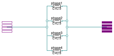
Model of an inductance with two electrical ports and neutral line cable
Information
Inductive model that connects two AC three-phase
unbalanced interfaces with neutral line. This model can be used to represent a
cable in a three-phase unbalanced AC system.
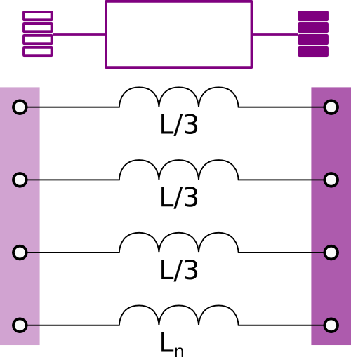
The model represents the lumped inductances as shown in the figure above.
Assuming that the inductance L is the overall inductance of the cable,
each line has an inductance equal to L/3.
The inductance of the neutral cable is defined separately using the parameter
Ln.
Extends from Buildings.Electrical.AC.ThreePhasesUnbalanced.Interfaces.TwoPort_N (Partial model interface for a two port component with neutral cable).
Parameters
Connectors
| Type | Name | Description |
|---|
| Terminal4_p | terminal_p | Electric terminal side p |
| Terminal4_n | terminal_n | Electric terminal side n |
Modelica definition
Model of an RL line parameterized with impedance matrices

Information
Resistive-inductive model that connects two AC three-phase
unbalanced interfaces. This model can be used to represent a
cable in a three-phase unbalanced AC system.
The voltage between the ports is

where Vi{p,n} is the voltage phasor at the connector p or
n of the i-th phase, while Iip
the current phasor entering from the connector p of the i-th phase.
The model is parameterized with an impedance matrix Z.
The matrix is symmetric thus just the upper triangular
part of it has to be defined.
Extends from Buildings.Electrical.AC.ThreePhasesUnbalanced.Interfaces.TwoPort (Partial model interface for a two port component without neutral cable).
Parameters
| Type | Name | Default | Description |
|---|
| Impedance | Z11[2] | | Element [1,1] of impedance matrix [Ohm] |
| Impedance | Z12[2] | | Element [1,2] of impedance matrix [Ohm] |
| Impedance | Z13[2] | | Element [1,3] of impedance matrix [Ohm] |
| Impedance | Z22[2] | | Element [2,2] of impedance matrix [Ohm] |
| Impedance | Z23[2] | | Element [2,3] of impedance matrix [Ohm] |
| Impedance | Z33[2] | | Element [3,3] of impedance matrix [Ohm] |
| Nominal conditions |
| Voltage | V_nominal | | Nominal voltage (V_nominal >= 0) [V] |
Modelica definition
model TwoPortMatrixRL
extends Buildings.Electrical.AC.ThreePhasesUnbalanced.Interfaces.TwoPort(
terminal_p(phase(v(
each nominal = V_nominal))),
terminal_n(phase(v(
each nominal = V_nominal))));
parameter Modelica.Units.SI.Voltage V_nominal(min=0, start=480)
;
parameter Modelica.Units.SI.Impedance Z11[2]
;
parameter Modelica.Units.SI.Impedance Z12[2]
;
parameter Modelica.Units.SI.Impedance Z13[2]
;
parameter Modelica.Units.SI.Impedance Z22[2]
;
parameter Modelica.Units.SI.Impedance Z23[2]
;
parameter Modelica.Units.SI.Impedance Z33[2]
;
final parameter Modelica.Units.SI.Impedance[2] Z21=Z12
;
final parameter Modelica.Units.SI.Impedance[2] Z31=Z13
;
final parameter Modelica.Units.SI.Impedance[2] Z32=Z23
;
Modelica.Units.SI.Current i1[2](
each stateSelect=StateSelect.prefer)=
terminal_n.phase[1].i ;
Modelica.Units.SI.Current i2[2](
each stateSelect=StateSelect.prefer)=
terminal_n.phase[2].i ;
Modelica.Units.SI.Current i3[2](
each stateSelect=StateSelect.prefer)=
terminal_n.phase[3].i ;
Modelica.Units.SI.Voltage v1_n[2](
start=
Buildings.Electrical.PhaseSystems.OnePhase.phaseVoltages(V_nominal/
sqrt(3), phi=0),
each stateSelect=StateSelect.never) = terminal_n.phase[1].v
;
Modelica.Units.SI.Voltage v2_n[2](
start=
Buildings.Electrical.PhaseSystems.OnePhase.phaseVoltages(V_nominal/
sqrt(3), phi=-2*Modelica.Constants.pi/3),
each stateSelect=StateSelect.never) = terminal_n.phase[2].v
;
Modelica.Units.SI.Voltage v3_n[2](
start=
Buildings.Electrical.PhaseSystems.OnePhase.phaseVoltages(V_nominal/
sqrt(3), phi=2*Modelica.Constants.pi/3),
each stateSelect=StateSelect.never) = terminal_n.phase[3].v
;
Modelica.Units.SI.Voltage v1_p[2](
start=
Buildings.Electrical.PhaseSystems.OnePhase.phaseVoltages(V_nominal/
sqrt(3), phi=0),
each stateSelect=StateSelect.never) = terminal_p.phase[1].v
;
Modelica.Units.SI.Voltage v2_p[2](
start=
Buildings.Electrical.PhaseSystems.OnePhase.phaseVoltages(V_nominal/
sqrt(3), phi=-2*Modelica.Constants.pi/3),
each stateSelect=StateSelect.never) = terminal_p.phase[2].v
;
Modelica.Units.SI.Voltage v3_p[2](
start=
Buildings.Electrical.PhaseSystems.OnePhase.phaseVoltages(V_nominal/
sqrt(3), phi=2*Modelica.Constants.pi/3),
each stateSelect=StateSelect.never) = terminal_p.phase[3].v
;
protected
function productAC1p =
Buildings.Electrical.PhaseSystems.OnePhase.product
;
equation
for i
in 1:3
loop
Connections.branch(terminal_p.phase[i].theta, terminal_n.phase[i].theta);
terminal_p.phase[i].theta = terminal_n.phase[i].theta;
terminal_p.phase[i].i = - terminal_n.phase[i].i;
end for;
v1_n - v1_p =
productAC1p(Z11, i1) +
productAC1p(Z12, i2) +
productAC1p(Z13, i3);
v2_n - v2_p =
productAC1p(Z21, i1) +
productAC1p(Z22, i2) +
productAC1p(Z23, i3);
v3_n - v3_p =
productAC1p(Z31, i1) +
productAC1p(Z32, i2) +
productAC1p(Z33, i3);
end TwoPortMatrixRL;
PI model of a line parameterized with impedance and admittance matrices
Information
RLC line model (π-model) that connects two AC three-phase
unbalanced interfaces. This model can be used to represent a
cable in a three-phase unbalanced AC system.
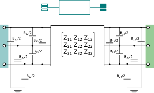
The model is parameterized with an impedance matrix Z and
an admittance matrix B.
The impedance matrix is symmetric, and therefore only the upper triangular
part of the matrix needs to be defined.
This model is a more detailed version of the model
Buildings.Electrical.AC.ThreePhasesUnbalanced.Lines.TwoPortMatrixRL that includes
the capacitive effects of the lines.
Extends from Buildings.Electrical.AC.ThreePhasesUnbalanced.Interfaces.TwoPort (Partial model interface for a two port component without neutral cable).
Parameters
| Type | Name | Default | Description |
|---|
| Impedance | Z11[2] | | Element [1,1] of impedance matrix [Ohm] |
| Impedance | Z12[2] | | Element [1,2] of impedance matrix [Ohm] |
| Impedance | Z13[2] | | Element [1,3] of impedance matrix [Ohm] |
| Impedance | Z22[2] | | Element [2,2] of impedance matrix [Ohm] |
| Impedance | Z23[2] | | Element [2,3] of impedance matrix [Ohm] |
| Impedance | Z33[2] | | Element [3,3] of impedance matrix [Ohm] |
| Admittance | B11 | | Element [1,1] of admittance matrix [S] |
| Admittance | B12 | | Element [1,2] of admittance matrix [S] |
| Admittance | B13 | | Element [1,3] of admittance matrix [S] |
| Admittance | B22 | | Element [2,2] of admittance matrix [S] |
| Admittance | B23 | | Element [2,3] of admittance matrix [S] |
| Admittance | B33 | | Element [3,3] of admittance matrix [S] |
| Nominal conditions |
| Voltage | V_nominal | | Nominal voltage (V_nominal >= 0) [V] |
Modelica definition
model TwoPortMatrixRLC
extends Buildings.Electrical.AC.ThreePhasesUnbalanced.Interfaces.TwoPort(
terminal_p(phase(v(
each nominal = V_nominal))),
terminal_n(phase(v(
each nominal = V_nominal))));
parameter Modelica.Units.SI.Voltage V_nominal(min=0, start=480)
;
parameter Modelica.Units.SI.Impedance Z11[2]
;
parameter Modelica.Units.SI.Impedance Z12[2]
;
parameter Modelica.Units.SI.Impedance Z13[2]
;
parameter Modelica.Units.SI.Impedance Z22[2]
;
parameter Modelica.Units.SI.Impedance Z23[2]
;
parameter Modelica.Units.SI.Impedance Z33[2]
;
final parameter Modelica.Units.SI.Impedance[2] Z21=Z12
;
final parameter Modelica.Units.SI.Impedance[2] Z31=Z13
;
final parameter Modelica.Units.SI.Impedance[2] Z32=Z23
;
parameter Modelica.Units.SI.Admittance B11
;
parameter Modelica.Units.SI.Admittance B12
;
parameter Modelica.Units.SI.Admittance B13
;
parameter Modelica.Units.SI.Admittance B22
;
parameter Modelica.Units.SI.Admittance B23
;
parameter Modelica.Units.SI.Admittance B33
;
final parameter Modelica.Units.SI.Admittance B21=B12
;
final parameter Modelica.Units.SI.Admittance B31=B13
;
final parameter Modelica.Units.SI.Admittance B32=B23
;
Modelica.Units.SI.Voltage v1_n[2](
start=
Buildings.Electrical.PhaseSystems.OnePhase.phaseVoltages(V_nominal/
sqrt(3), phi=0),
each stateSelect=StateSelect.never) = terminal_n.phase[1].v
;
Modelica.Units.SI.Voltage v2_n[2](
start=
Buildings.Electrical.PhaseSystems.OnePhase.phaseVoltages(V_nominal/
sqrt(3), phi=-2*Modelica.Constants.pi/3),
each stateSelect=StateSelect.never) = terminal_n.phase[2].v
;
Modelica.Units.SI.Voltage v3_n[2](
start=
Buildings.Electrical.PhaseSystems.OnePhase.phaseVoltages(V_nominal/
sqrt(3), phi=2*Modelica.Constants.pi/3),
each stateSelect=StateSelect.never) = terminal_n.phase[3].v
;
Modelica.Units.SI.Voltage v1_p[2](
start=
Buildings.Electrical.PhaseSystems.OnePhase.phaseVoltages(V_nominal/
sqrt(3), phi=0),
each stateSelect=StateSelect.never) = terminal_p.phase[1].v
;
Modelica.Units.SI.Voltage v2_p[2](
start=
Buildings.Electrical.PhaseSystems.OnePhase.phaseVoltages(V_nominal/
sqrt(3), phi=-2*Modelica.Constants.pi/3),
each stateSelect=StateSelect.never) = terminal_p.phase[2].v
;
Modelica.Units.SI.Voltage v3_p[2](
start=
Buildings.Electrical.PhaseSystems.OnePhase.phaseVoltages(V_nominal/
sqrt(3), phi=2*Modelica.Constants.pi/3),
each stateSelect=StateSelect.never) = terminal_p.phase[3].v
;
protected
function productAC1p =
Buildings.Electrical.PhaseSystems.OnePhase.product
;
Modelica.Units.SI.Current Isr[3,2](start=
zeros(3, Buildings.Electrical.PhaseSystems.OnePhase.n),
each stateSelect=StateSelect.prefer)
;
Modelica.Units.SI.Current Ish_p[3,2](start=
zeros(3, Buildings.Electrical.PhaseSystems.OnePhase.n),
each stateSelect=StateSelect.prefer) ;
Modelica.Units.SI.Current Ish_n[3,2](start=
zeros(3, Buildings.Electrical.PhaseSystems.OnePhase.n),
each stateSelect=StateSelect.prefer) ;
equation
for i
in 1:3
loop
Connections.branch(terminal_p.phase[i].theta, terminal_n.phase[i].theta);
terminal_p.phase[i].theta = terminal_n.phase[i].theta;
end for;
Isr[1,:] = terminal_n.phase[1].i - Ish_n[1,:];
Isr[2,:] = terminal_n.phase[2].i - Ish_n[2,:];
Isr[3,:] = terminal_n.phase[3].i - Ish_n[3,:];
Isr[1,:] + terminal_p.phase[1].i = Ish_p[1,:];
Isr[2,:] + terminal_p.phase[2].i = Ish_p[2,:];
Isr[3,:] + terminal_p.phase[3].i = Ish_p[3,:];
terminal_n.phase[1].v - terminal_p.phase[1].v =
productAC1p(Z11, terminal_n.phase[1].i)
+
productAC1p(Z12, terminal_n.phase[2].i)
+
productAC1p(Z13, terminal_n.phase[3].i);
terminal_n.phase[2].v - terminal_p.phase[2].v =
productAC1p(Z21, terminal_n.phase[1].i)
+
productAC1p(Z22, terminal_n.phase[2].i)
+
productAC1p(Z23, terminal_n.phase[3].i);
terminal_n.phase[3].v - terminal_p.phase[3].v =
productAC1p(Z31, terminal_n.phase[1].i)
+
productAC1p(Z32, terminal_n.phase[2].i)
+
productAC1p(Z33, terminal_n.phase[3].i);
Ish_n[1,:] =
productAC1p({0, B11/2}, v1_n)
+
productAC1p({0, B12/2}, v2_n)
+
productAC1p({0, B13/2}, v3_n);
Ish_n[2,:] =
productAC1p({0, B21/2}, v1_n)
+
productAC1p({0, B22/2}, v2_n)
+
productAC1p({0, B23/2}, v3_n);
Ish_n[3,:] =
productAC1p({0, B31/2}, v1_n)
+
productAC1p({0, B32/2}, v2_n)
+
productAC1p({0, B33/2}, v3_n);
Ish_p[1,:] =
productAC1p({0, B11/2}, v1_p)
+
productAC1p({0, B12/2}, v2_p)
+
productAC1p({0, B13/2}, v3_p);
Ish_p[2,:] =
productAC1p({0, B21/2}, v1_p)
+
productAC1p({0, B22/2}, v2_p)
+
productAC1p({0, B23/2}, v3_p);
Ish_p[3,:] =
productAC1p({0, B31/2}, v1_p)
+
productAC1p({0, B32/2}, v2_p)
+
productAC1p({0, B33/2}, v3_p);
end TwoPortMatrixRLC;
PI model of a line parameterized with impedance and admittance matrices and neutral line

Information
RLC line model (π-model) that connects two AC three-phase
unbalanced interfaces and neutral line. This model can be used to represent a
cable in a three-phase unbalanced AC system.
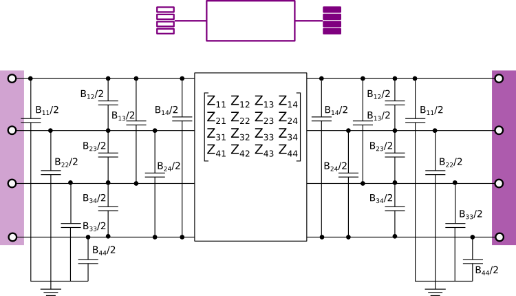
The model is parameterized with an impedance matrix Z and
an admittance matrix B.
The impedance matrix is symmetric, and therefore only the upper triangular
part of the matrix needs to be defined.
This model is a more detailed version of the model
Buildings.Electrical.AC.ThreePhasesUnbalanced.Lines.TwoPortMatrixRL_N that includes
the capacitive effects of the lines.
Note
The fourth line is the neutral one.
Extends from Buildings.Electrical.AC.ThreePhasesUnbalanced.Interfaces.TwoPort_N (Partial model interface for a two port component with neutral cable).
Parameters
| Type | Name | Default | Description |
|---|
| Impedance | Z11[2] | | Element [1,1] of impedance matrix [Ohm] |
| Impedance | Z12[2] | | Element [1,2] of impedance matrix [Ohm] |
| Impedance | Z13[2] | | Element [1,3] of impedance matrix [Ohm] |
| Impedance | Z14[2] | | Element [1,4] of impedance matrix [Ohm] |
| Impedance | Z22[2] | | Element [2,2] of impedance matrix [Ohm] |
| Impedance | Z23[2] | | Element [2,3] of impedance matrix [Ohm] |
| Impedance | Z24[2] | | Element [2,4] of impedance matrix [Ohm] |
| Impedance | Z33[2] | | Element [3,3] of impedance matrix [Ohm] |
| Impedance | Z34[2] | | Element [3,4] of impedance matrix [Ohm] |
| Impedance | Z44[2] | | Element [4,4] of impedance matrix [Ohm] |
| Admittance | B11 | | Element [1,1] of admittance matrix [S] |
| Admittance | B12 | | Element [1,2] of admittance matrix [S] |
| Admittance | B13 | | Element [1,3] of admittance matrix [S] |
| Admittance | B14 | | Element [1,4] of admittance matrix [S] |
| Admittance | B22 | | Element [2,2] of admittance matrix [S] |
| Admittance | B23 | | Element [2,3] of admittance matrix [S] |
| Admittance | B24 | | Element [2,4] of admittance matrix [S] |
| Admittance | B33 | | Element [3,3] of admittance matrix [S] |
| Admittance | B34 | | Element [3,4] of admittance matrix [S] |
| Admittance | B44 | | Element [4,4] of admittance matrix [S] |
| Nominal conditions |
| Voltage | V_nominal | | Nominal voltage (V_nominal >= 0) [V] |
Modelica definition
model TwoPortMatrixRLC_N
extends Buildings.Electrical.AC.ThreePhasesUnbalanced.Interfaces.TwoPort_N(
terminal_p(phase(v(
each nominal = V_nominal))),
terminal_n(phase(v(
each nominal = V_nominal))));
parameter Modelica.Units.SI.Voltage V_nominal(min=0, start=480)
;
parameter Modelica.Units.SI.Impedance Z11[2]
;
parameter Modelica.Units.SI.Impedance Z12[2]
;
parameter Modelica.Units.SI.Impedance Z13[2]
;
parameter Modelica.Units.SI.Impedance Z14[2]
;
parameter Modelica.Units.SI.Impedance Z22[2]
;
parameter Modelica.Units.SI.Impedance Z23[2]
;
parameter Modelica.Units.SI.Impedance Z24[2]
;
parameter Modelica.Units.SI.Impedance Z33[2]
;
parameter Modelica.Units.SI.Impedance Z34[2]
;
parameter Modelica.Units.SI.Impedance Z44[2]
;
final parameter Modelica.Units.SI.Impedance[2] Z21=Z12
;
final parameter Modelica.Units.SI.Impedance[2] Z31=Z13
;
final parameter Modelica.Units.SI.Impedance[2] Z32=Z23
;
final parameter Modelica.Units.SI.Impedance[2] Z41=Z14
;
final parameter Modelica.Units.SI.Impedance[2] Z42=Z24
;
final parameter Modelica.Units.SI.Impedance[2] Z43=Z34
;
parameter Modelica.Units.SI.Admittance B11
;
parameter Modelica.Units.SI.Admittance B12
;
parameter Modelica.Units.SI.Admittance B13
;
parameter Modelica.Units.SI.Admittance B14
;
parameter Modelica.Units.SI.Admittance B22
;
parameter Modelica.Units.SI.Admittance B23
;
parameter Modelica.Units.SI.Admittance B24
;
parameter Modelica.Units.SI.Admittance B33
;
parameter Modelica.Units.SI.Admittance B34
;
parameter Modelica.Units.SI.Admittance B44
;
final parameter Modelica.Units.SI.Admittance B21=B12
;
final parameter Modelica.Units.SI.Admittance B31=B13
;
final parameter Modelica.Units.SI.Admittance B32=B23
;
final parameter Modelica.Units.SI.Admittance B41=B14
;
final parameter Modelica.Units.SI.Admittance B42=B24
;
final parameter Modelica.Units.SI.Admittance B43=B34
;
Modelica.Units.SI.Voltage v1_n[2](
start=
Buildings.Electrical.PhaseSystems.OnePhase.phaseVoltages(V_nominal/
sqrt(3), phi=0),
each stateSelect=StateSelect.never) = terminal_n.phase[1].v
;
Modelica.Units.SI.Voltage v2_n[2](
start=
Buildings.Electrical.PhaseSystems.OnePhase.phaseVoltages(V_nominal/
sqrt(3), phi=-2*Modelica.Constants.pi/3),
each stateSelect=StateSelect.never) = terminal_n.phase[2].v
;
Modelica.Units.SI.Voltage v3_n[2](
start=
Buildings.Electrical.PhaseSystems.OnePhase.phaseVoltages(V_nominal/
sqrt(3), phi=2*Modelica.Constants.pi/3),
each stateSelect=StateSelect.never) = terminal_n.phase[3].v
;
Modelica.Units.SI.Voltage v4_n[2](
start=
Buildings.Electrical.PhaseSystems.OnePhase.phaseVoltages(0),
each stateSelect=StateSelect.never) = terminal_n.phase[4].v
;
Modelica.Units.SI.Voltage v1_p[2](
start=
Buildings.Electrical.PhaseSystems.OnePhase.phaseVoltages(V_nominal/
sqrt(3), phi=0),
each stateSelect=StateSelect.never) = terminal_p.phase[1].v
;
Modelica.Units.SI.Voltage v2_p[2](
start=
Buildings.Electrical.PhaseSystems.OnePhase.phaseVoltages(V_nominal/
sqrt(3), phi=-2*Modelica.Constants.pi/3),
each stateSelect=StateSelect.never) = terminal_p.phase[2].v
;
Modelica.Units.SI.Voltage v3_p[2](
start=
Buildings.Electrical.PhaseSystems.OnePhase.phaseVoltages(V_nominal/
sqrt(3), phi=2*Modelica.Constants.pi/3),
each stateSelect=StateSelect.never) = terminal_p.phase[3].v
;
Modelica.Units.SI.Voltage v4_p[2](
start=
Buildings.Electrical.PhaseSystems.OnePhase.phaseVoltages(0),
each stateSelect=StateSelect.never) = terminal_p.phase[4].v
;
protected
function productAC1p =
Buildings.Electrical.PhaseSystems.OnePhase.product
;
Modelica.Units.SI.Current Isr[4,2](
each stateSelect=StateSelect.prefer)
;
Modelica.Units.SI.Current Ish_p[4,2](
each stateSelect=StateSelect.prefer)
;
Modelica.Units.SI.Current Ish_n[4,2](
each stateSelect=StateSelect.prefer)
;
equation
for i
in 1:4
loop
Connections.branch(terminal_p.phase[i].theta, terminal_n.phase[i].theta);
terminal_p.phase[i].theta = terminal_n.phase[i].theta;
end for;
Isr[1,:] = terminal_n.phase[1].i - Ish_n[1,:];
Isr[2,:] = terminal_n.phase[2].i - Ish_n[2,:];
Isr[3,:] = terminal_n.phase[3].i - Ish_n[3,:];
Isr[4,:] = terminal_n.phase[4].i - Ish_n[4,:];
Isr[1,:] + terminal_p.phase[1].i = Ish_p[1,:];
Isr[2,:] + terminal_p.phase[2].i = Ish_p[2,:];
Isr[3,:] + terminal_p.phase[3].i = Ish_p[3,:];
Isr[4,:] + terminal_p.phase[4].i = Ish_p[4,:];
terminal_n.phase[1].v - terminal_p.phase[1].v =
productAC1p(Z11, terminal_n.phase[1].i)
+
productAC1p(Z12, terminal_n.phase[2].i)
+
productAC1p(Z13, terminal_n.phase[3].i)
+
productAC1p(Z14, terminal_n.phase[4].i);
terminal_n.phase[2].v - terminal_p.phase[2].v =
productAC1p(Z21, terminal_n.phase[1].i)
+
productAC1p(Z22, terminal_n.phase[2].i)
+
productAC1p(Z23, terminal_n.phase[3].i)
+
productAC1p(Z24, terminal_n.phase[4].i);
terminal_n.phase[3].v - terminal_p.phase[3].v =
productAC1p(Z31, terminal_n.phase[1].i)
+
productAC1p(Z32, terminal_n.phase[2].i)
+
productAC1p(Z33, terminal_n.phase[3].i)
+
productAC1p(Z34, terminal_n.phase[4].i);
terminal_n.phase[4].v - terminal_p.phase[4].v =
productAC1p(Z41, terminal_n.phase[1].i)
+
productAC1p(Z42, terminal_n.phase[2].i)
+
productAC1p(Z43, terminal_n.phase[3].i)
+
productAC1p(Z44, terminal_n.phase[4].i);
Ish_n[1,:] =
productAC1p({0, B11/2}, v1_n)
+
productAC1p({0, B12/2}, v2_n)
+
productAC1p({0, B13/2}, v3_n)
+
productAC1p({0, B14/2}, v4_n);
Ish_n[2,:] =
productAC1p({0, B21/2}, v1_n)
+
productAC1p({0, B22/2}, v2_n)
+
productAC1p({0, B23/2}, v3_n)
+
productAC1p({0, B24/2}, v4_n);
Ish_n[3,:] =
productAC1p({0, B31/2}, v1_n)
+
productAC1p({0, B32/2}, v2_n)
+
productAC1p({0, B33/2}, v3_n)
+
productAC1p({0, B34/2}, v4_n);
Ish_n[4,:] =
productAC1p({0, B41/2}, v1_n)
+
productAC1p({0, B42/2}, v2_n)
+
productAC1p({0, B43/2}, v3_n)
+
productAC1p({0, B44/2}, v4_n);
Ish_p[1,:] =
productAC1p({0, B11/2}, v1_p)
+
productAC1p({0, B12/2}, v2_p)
+
productAC1p({0, B13/2}, v3_p)
+
productAC1p({0, B14/2}, v4_p);
Ish_p[2,:] =
productAC1p({0, B21/2}, v1_p)
+
productAC1p({0, B22/2}, v2_p)
+
productAC1p({0, B23/2}, v3_p)
+
productAC1p({0, B24/2}, v4_p);
Ish_p[3,:] =
productAC1p({0, B31/2}, v1_p)
+
productAC1p({0, B32/2}, v2_p)
+
productAC1p({0, B33/2}, v3_p)
+
productAC1p({0, B34/2}, v4_p);
Ish_p[4,:] =
productAC1p({0, B41/2}, v1_p)
+
productAC1p({0, B42/2}, v2_p)
+
productAC1p({0, B43/2}, v3_p)
+
productAC1p({0, B44/2}, v4_p);
end TwoPortMatrixRLC_N;
Model of an RL line parameterized with impedance matrices and neutral line
Information
Resistive-inductive model that connects two AC three-phase
unbalanced interfaces with neutral line. This model can be used to represent a
cable in a three-phase unbalanced AC system.
The voltage between the ports is

where Vi{p,n} is the voltage phasor at the connector p or
n of the i-th phase, while Iip
the current phasor entering from the connector p of the i-th phase.
The model is parameterized with an impedance matrix Z.
The matrix is symmetric thus just the upper triangular
part of it has to be defined.
Note
The fourth line is the neutral one.
Extends from Buildings.Electrical.AC.ThreePhasesUnbalanced.Interfaces.TwoPort_N (Partial model interface for a two port component with neutral cable).
Parameters
| Type | Name | Default | Description |
|---|
| Impedance | Z11[2] | | Element [1,1] of impedance matrix [Ohm] |
| Impedance | Z12[2] | | Element [1,2] of impedance matrix [Ohm] |
| Impedance | Z13[2] | | Element [1,3] of impedance matrix [Ohm] |
| Impedance | Z14[2] | | Element [1,4] of impedance matrix [Ohm] |
| Impedance | Z22[2] | | Element [2,2] of impedance matrix [Ohm] |
| Impedance | Z23[2] | | Element [2,3] of impedance matrix [Ohm] |
| Impedance | Z24[2] | | Element [2,4] of impedance matrix [Ohm] |
| Impedance | Z33[2] | | Element [3,3] of impedance matrix [Ohm] |
| Impedance | Z34[2] | | Element [3,4] of impedance matrix [Ohm] |
| Impedance | Z44[2] | | Element [4,4] of impedance matrix [Ohm] |
| Nominal conditions |
| Voltage | V_nominal | | Nominal voltage (V_nominal >= 0) [V] |
Modelica definition
model TwoPortMatrixRL_N
extends Buildings.Electrical.AC.ThreePhasesUnbalanced.Interfaces.TwoPort_N(
terminal_p(phase(v(
each nominal = V_nominal))),
terminal_n(phase(v(
each nominal = V_nominal))));
parameter Modelica.Units.SI.Voltage V_nominal(min=0, start=480)
;
parameter Modelica.Units.SI.Impedance Z11[2]
;
parameter Modelica.Units.SI.Impedance Z12[2]
;
parameter Modelica.Units.SI.Impedance Z13[2]
;
parameter Modelica.Units.SI.Impedance Z14[2]
;
parameter Modelica.Units.SI.Impedance Z22[2]
;
parameter Modelica.Units.SI.Impedance Z23[2]
;
parameter Modelica.Units.SI.Impedance Z24[2]
;
parameter Modelica.Units.SI.Impedance Z33[2]
;
parameter Modelica.Units.SI.Impedance Z34[2]
;
parameter Modelica.Units.SI.Impedance Z44[2]
;
final parameter Modelica.Units.SI.Impedance[2] Z21=Z12
;
final parameter Modelica.Units.SI.Impedance[2] Z31=Z13
;
final parameter Modelica.Units.SI.Impedance[2] Z32=Z23
;
final parameter Modelica.Units.SI.Impedance[2] Z41=Z14
;
final parameter Modelica.Units.SI.Impedance[2] Z42=Z24
;
final parameter Modelica.Units.SI.Impedance[2] Z43=Z34
;
Modelica.Units.SI.Current i1[2](
each stateSelect=StateSelect.prefer)=
terminal_n.phase[1].i ;
Modelica.Units.SI.Current i2[2](
each stateSelect=StateSelect.prefer)=
terminal_n.phase[2].i ;
Modelica.Units.SI.Current i3[2](
each stateSelect=StateSelect.prefer)=
terminal_n.phase[3].i ;
Modelica.Units.SI.Current i4[2](
each stateSelect=StateSelect.prefer)=
terminal_n.phase[4].i ;
Modelica.Units.SI.Voltage v1_n[2](
start=
Buildings.Electrical.PhaseSystems.OnePhase.phaseVoltages(V_nominal/
sqrt(3), phi=0),
each stateSelect=StateSelect.never) = terminal_n.phase[1].v
;
Modelica.Units.SI.Voltage v2_n[2](
start=
Buildings.Electrical.PhaseSystems.OnePhase.phaseVoltages(V_nominal/
sqrt(3), phi=-2*Modelica.Constants.pi/3),
each stateSelect=StateSelect.never) = terminal_n.phase[2].v
;
Modelica.Units.SI.Voltage v3_n[2](
start=
Buildings.Electrical.PhaseSystems.OnePhase.phaseVoltages(V_nominal/
sqrt(3), phi=2*Modelica.Constants.pi/3),
each stateSelect=StateSelect.never) = terminal_n.phase[3].v
;
Modelica.Units.SI.Voltage v4_n[2](
start=
Buildings.Electrical.PhaseSystems.OnePhase.phaseVoltages(0),
each stateSelect=StateSelect.never) = terminal_n.phase[4].v
;
Modelica.Units.SI.Voltage v1_p[2](
start=
Buildings.Electrical.PhaseSystems.OnePhase.phaseVoltages(V_nominal/
sqrt(3), phi=0),
each stateSelect=StateSelect.never) = terminal_p.phase[1].v
;
Modelica.Units.SI.Voltage v2_p[2](
start=
Buildings.Electrical.PhaseSystems.OnePhase.phaseVoltages(V_nominal/
sqrt(3), phi=-2*Modelica.Constants.pi/3),
each stateSelect=StateSelect.never) = terminal_p.phase[2].v
;
Modelica.Units.SI.Voltage v3_p[2](
start=
Buildings.Electrical.PhaseSystems.OnePhase.phaseVoltages(V_nominal/
sqrt(3), phi=2*Modelica.Constants.pi/3),
each stateSelect=StateSelect.never) = terminal_p.phase[3].v
;
Modelica.Units.SI.Voltage v4_p[2](
start=
Buildings.Electrical.PhaseSystems.OnePhase.phaseVoltages(0),
each stateSelect=StateSelect.never) = terminal_p.phase[4].v
;
protected
function productAC1p =
Buildings.Electrical.PhaseSystems.OnePhase.product
;
equation
for i
in 1:4
loop
Connections.branch(terminal_p.phase[i].theta, terminal_n.phase[i].theta);
terminal_p.phase[i].theta = terminal_n.phase[i].theta;
terminal_p.phase[i].i = - terminal_n.phase[i].i;
end for;
v1_n - v1_p =
productAC1p(Z11, i1) +
productAC1p(Z12, i2) +
productAC1p(Z13, i3)+
productAC1p(Z14, i4);
v2_n - v2_p =
productAC1p(Z21, i1) +
productAC1p(Z22, i2) +
productAC1p(Z23, i3)+
productAC1p(Z24, i4);
v3_n - v3_p =
productAC1p(Z31, i1) +
productAC1p(Z32, i2) +
productAC1p(Z33, i3)+
productAC1p(Z34, i4);
v4_n - v4_p =
productAC1p(Z41, i1) +
productAC1p(Z42, i2) +
productAC1p(Z43, i3)+
productAC1p(Z44, i4);
end TwoPortMatrixRL_N;
Model of a resistive-inductive element with two electrical ports
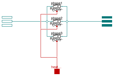
Information
Resistive-inductive model that connects two AC three-phase
unbalanced interfaces. This model can be used to represent a
cable in a three-phase unbalanced AC system.
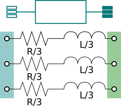
The model represents the lumped impedances as shown in the figure above.
Assuming that the overall cable has a resistance R and an inductance
L, each line has an inductance equal to L/3 and a resistance
equal to R/3.
Extends from Modelica.Electrical.Analog.Interfaces.ConditionalHeatPort (Partial model to include a conditional HeatPort in order to describe the power loss via a thermal network), Buildings.Electrical.AC.ThreePhasesUnbalanced.Interfaces.TwoPort (Partial model interface for a two port component without neutral cable).
Parameters
| Type | Name | Default | Description |
|---|
| Boolean | useHeatPort | false | = true, if heatPort is enabled |
| Temperature | T | 293.15 | Fixed device temperature if useHeatPort = false [K] |
| Resistance | R | | Resistance at temperature T_ref [Ohm] |
| Temperature | T_ref | 298.15 | Reference temperature [K] |
| Temperature | M | 507.65 | Temperature constant (R_actual = R*(M + T_heatPort)/(M + T_ref)) [K] |
| Inductance | L | | Inductance [H] |
| Current | i1_start[2] | {0,0} | Initial current phasor of phase 1 (positive if entering from terminal p) [A] |
| Current | i2_start[2] | {0,0} | Initial current phasor of phase 2 (positive if entering from terminal p) [A] |
| Current | i3_start[2] | {0,0} | Initial current phasor of phase 3 (positive if entering from terminal p) [A] |
| Modeling assumption |
| Load | mode | Buildings.Electrical.Types.L... | Type of model (e.g., steady state, dynamic, prescribed power consumption, etc.) |
Connectors
Modelica definition
model TwoPortRL
extends Modelica.Electrical.Analog.Interfaces.ConditionalHeatPort;
extends Buildings.Electrical.AC.ThreePhasesUnbalanced.Interfaces.TwoPort;
parameter Modelica.Units.SI.Resistance R ;
parameter Modelica.Units.SI.Temperature T_ref=298.15 ;
parameter Modelica.Units.SI.Temperature M=507.65
;
parameter Modelica.Units.SI.Inductance L ;
parameter Modelica.Units.SI.Current i1_start[2]={0,0}
;
parameter Modelica.Units.SI.Current i2_start[2]={0,0}
;
parameter Modelica.Units.SI.Current i3_start[2]={0,0}
;
parameter Buildings.Electrical.Types.Load mode(
min=Buildings.Electrical.Types.Load.FixedZ_steady_state,
max=Buildings.Electrical.Types.Load.FixedZ_dynamic) = Buildings.Electrical.Types.Load.FixedZ_steady_state
;
OnePhase.Lines.TwoPortRL phase1(
final T_ref=T_ref,
final M=M,
final R=R/3,
final L=L/3,
final mode=mode,
final useHeatPort=useHeatPort,
i_start=i1_start) ;
OnePhase.Lines.TwoPortRL phase2(
final T_ref=T_ref,
final M=M,
final R=R/3,
final L=L/3,
final mode=mode,
final useHeatPort=useHeatPort,
i_start=i2_start) ;
OnePhase.Lines.TwoPortRL phase3(
final T_ref=T_ref,
final M=M,
final R=R/3,
final L=L/3,
final mode=mode,
final useHeatPort=useHeatPort,
i_start=i3_start) ;
equation
LossPower = phase1.LossPower + phase2.LossPower + phase3.LossPower;
connect(terminal_n.phase[1], phase1.terminal_n);
connect(terminal_n.phase[2], phase2.terminal_n);
connect(terminal_n.phase[3], phase3.terminal_n);
connect(phase1.terminal_p, terminal_p.phase[1]);
connect(phase2.terminal_p, terminal_p.phase[2]);
connect(phase3.terminal_p, terminal_p.phase[3]);
connect(phase1.heatPort, heatPort);
connect(phase3.heatPort, heatPort);
connect(phase2.heatPort, heatPort);
end TwoPortRL;
Model of an RLC element with two electrical ports
Information
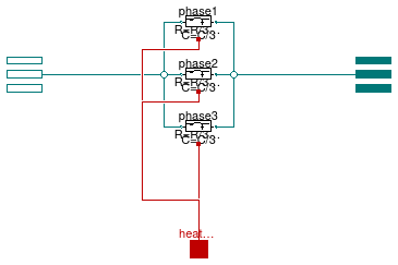
RLC line model (T-model) that connects two AC three-phase
unbalanced interfaces. This model can be used to represent a
cable in a three-phase unbalanced AC system.
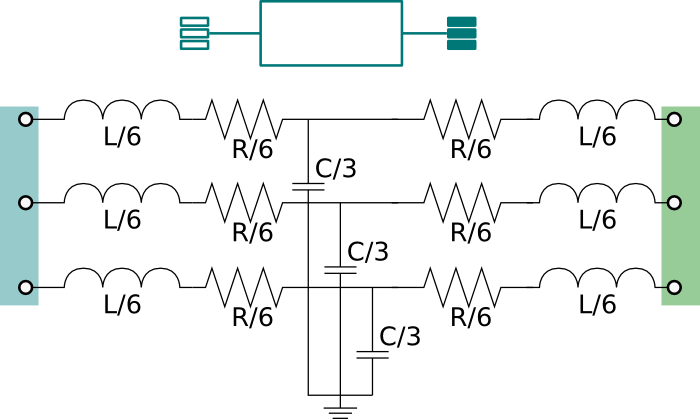
The model represents the lumped impedances as shown in the figure above.
Assuming that the overall cable has a resistance R, an inductance
L, and a capacitance C, each line has an inductance equal
to L/3, a resistance equal to R/3 and a capacity equal to
C/3.
Extends from Modelica.Electrical.Analog.Interfaces.ConditionalHeatPort (Partial model to include a conditional HeatPort in order to describe the power loss via a thermal network), Buildings.Electrical.AC.ThreePhasesUnbalanced.Interfaces.TwoPort (Partial model interface for a two port component without neutral cable).
Parameters
| Type | Name | Default | Description |
|---|
| Boolean | useHeatPort | false | = true, if heatPort is enabled |
| Temperature | T | 293.15 | Fixed device temperature if useHeatPort = false [K] |
| Resistance | R | | Resistance at temperature T_ref [Ohm] |
| Capacitance | C | | Capacity [F] |
| Inductance | L | | Inductance [H] |
| Temperature | T_ref | 298.15 | Reference temperature [K] |
| Temperature | M | 507.65 | Temperature constant (R_actual = R*(M + T_heatPort)/(M + T_ref)) [K] |
| Voltage | Vc1_start[2] | V_nominal/sqrt(3)*{1,0} | Initial voltage phasor of the capacitance located in the middle of phase 1 [V] |
| Voltage | Vc2_start[2] | V_nominal/sqrt(3)*{-1/2,-sqr... | Initial voltage phasor of the capacitance located in the middle of phase 1 [V] |
| Voltage | Vc3_start[2] | V_nominal/sqrt(3)*{-1/2,+sqr... | Initial voltage phasor of the capacitance located in the middle of phase 1 [V] |
| Modeling assumption |
| Load | mode | Buildings.Electrical.Types.L... | Type of model (e.g., steady state, dynamic, prescribed power consumption, etc.) |
| Nominal conditions |
| Voltage | V_nominal | | Nominal voltage (V_nominal >= 0) [V] |
Connectors
| Type | Name | Description |
|---|
| HeatPort_a | heatPort | Conditional heat port |
Modelica definition
model TwoPortRLC
extends Modelica.Electrical.Analog.Interfaces.ConditionalHeatPort;
extends Buildings.Electrical.AC.ThreePhasesUnbalanced.Interfaces.TwoPort(
terminal_p(phase(v(
each nominal = V_nominal))),
terminal_n(phase(v(
each nominal = V_nominal))));
parameter Modelica.Units.SI.Resistance R ;
parameter Modelica.Units.SI.Capacitance C ;
parameter Modelica.Units.SI.Inductance L ;
parameter Modelica.Units.SI.Temperature T_ref=298.15 ;
parameter Modelica.Units.SI.Temperature M=507.65
;
parameter Modelica.Units.SI.Voltage Vc1_start[2]=V_nominal/
sqrt(3)*{1,0}
;
parameter Modelica.Units.SI.Voltage Vc2_start[2]=V_nominal/
sqrt(3)*{-1/2,-
sqrt(3)/2}
;
parameter Modelica.Units.SI.Voltage Vc3_start[2]=V_nominal/
sqrt(3)*{-1/2,+
sqrt(3)/2}
;
parameter Buildings.Electrical.Types.Load mode(
min=Buildings.Electrical.Types.Load.FixedZ_steady_state,
max=Buildings.Electrical.Types.Load.FixedZ_dynamic)=
Buildings.Electrical.Types.Load.FixedZ_steady_state
;
parameter Modelica.Units.SI.Voltage V_nominal(min=0, start=480)
;
OnePhase.Lines.TwoPortRLC phase1(
final T_ref=T_ref,
final M=M,
final R=R/3,
final L=L/3,
final C=C/3,
final mode=mode,
final V_nominal = V_nominal/
sqrt(3),
final useHeatPort=useHeatPort,
Vc_start=Vc1_start) ;
OnePhase.Lines.TwoPortRLC phase2(
final T_ref=T_ref,
final M=M,
final R=R/3,
final L=L/3,
final C=C/3,
final mode=mode,
final V_nominal = V_nominal/
sqrt(3),
final useHeatPort=useHeatPort,
Vc_start=Vc2_start) ;
OnePhase.Lines.TwoPortRLC phase3(
final T_ref=T_ref,
final M=M,
final R=R/3,
final L=L/3,
final C=C/3,
final mode=mode,
final V_nominal = V_nominal/
sqrt(3),
final useHeatPort=useHeatPort,
Vc_start=Vc3_start) ;
equation
LossPower = phase1.LossPower + phase2.LossPower + phase3.LossPower;
connect(terminal_n.phase[1], phase1.terminal_n);
connect(terminal_n.phase[2], phase2.terminal_n);
connect(terminal_n.phase[3], phase3.terminal_n);
connect(phase1.terminal_p, terminal_p.phase[1]);
connect(phase2.terminal_p, terminal_p.phase[2]);
connect(phase3.terminal_p, terminal_p.phase[3]);
connect(phase1.heatPort, heatPort);
connect(phase3.heatPort, heatPort);
connect(phase2.heatPort, heatPort);
end TwoPortRLC;
Model of an RLC element with two electrical ports and neutral line cable
Information
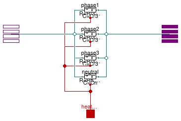
RLC line model (T-model) that connects two AC three-phase
unbalanced interfaces with neutral line. This model can be used to represent a
cable in a three-phase unbalanced AC system.
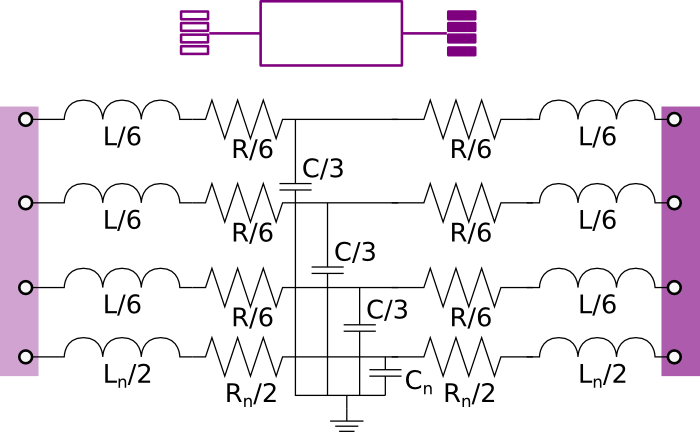
The model represents the lumped impedances as shown in the figure above.
Assuming that the overall cable has a resistance R, an inductance
L, and a capacitance C, each line has an inductance equal
to L/3, a resistance equal to R/3 and a capacity equal to
C/3.
The resistance, capacitance and inductance of the neutral cable are defined separately using the parameters
Rn Cn, and Ln.
Extends from Modelica.Electrical.Analog.Interfaces.ConditionalHeatPort (Partial model to include a conditional HeatPort in order to describe the power loss via a thermal network), Buildings.Electrical.AC.ThreePhasesUnbalanced.Interfaces.TwoPort_N (Partial model interface for a two port component with neutral cable).
Parameters
| Type | Name | Default | Description |
|---|
| Boolean | useHeatPort | false | = true, if heatPort is enabled |
| Temperature | T | 293.15 | Fixed device temperature if useHeatPort = false [K] |
| Resistance | R | | Resistance at temperature T_ref [Ohm] |
| Resistance | Rn | | Resistance of neutral cable at temperature T_ref [Ohm] |
| Capacitance | C | | Capacity [F] |
| Capacitance | Cn | | Capacityof neutral cable [F] |
| Inductance | L | | Inductance [H] |
| Inductance | Ln | | Inductance of neutral cable [H] |
| Temperature | T_ref | 298.15 | Reference temperature [K] |
| Temperature | M | 507.65 | Temperature constant (R_actual = R*(M + T_heatPort)/(M + T_ref)) [K] |
| Voltage | Vc1_start[2] | V_nominal/sqrt(3)*{1,0} | Initial voltage phasor of the capacitance located in the middle of phase 1 [V] |
| Voltage | Vc2_start[2] | V_nominal/sqrt(3)*{-1/2,-sqr... | Initial voltage phasor of the capacitance located in the middle of phase 1 [V] |
| Voltage | Vc3_start[2] | V_nominal/sqrt(3)*{-1/2,+sqr... | Initial voltage phasor of the capacitance located in the middle of phase 1 [V] |
| Modeling assumption |
| Load | mode | Buildings.Electrical.Types.L... | Type of model (e.g., steady state, dynamic, prescribed power consumption, etc.) |
| Nominal conditions |
| Voltage | V_nominal | | Nominal voltage (V_nominal >= 0) [V] |
Connectors
| Type | Name | Description |
|---|
| HeatPort_a | heatPort | Conditional heat port |
Modelica definition
model TwoPortRLC_N
extends Modelica.Electrical.Analog.Interfaces.ConditionalHeatPort;
extends Buildings.Electrical.AC.ThreePhasesUnbalanced.Interfaces.TwoPort_N(
terminal_p(phase(v(
each nominal = V_nominal))),
terminal_n(phase(v(
each nominal = V_nominal))));
parameter Modelica.Units.SI.Resistance R ;
parameter Modelica.Units.SI.Resistance Rn
;
parameter Modelica.Units.SI.Capacitance C ;
parameter Modelica.Units.SI.Capacitance Cn ;
parameter Modelica.Units.SI.Inductance L ;
parameter Modelica.Units.SI.Inductance Ln ;
parameter Modelica.Units.SI.Temperature T_ref=298.15 ;
parameter Modelica.Units.SI.Temperature M=507.65
;
parameter Modelica.Units.SI.Voltage Vc1_start[2]=V_nominal/
sqrt(3)*{1,0}
;
parameter Modelica.Units.SI.Voltage Vc2_start[2]=V_nominal/
sqrt(3)*{-1/2,-
sqrt(3)/2}
;
parameter Modelica.Units.SI.Voltage Vc3_start[2]=V_nominal/
sqrt(3)*{-1/2,+
sqrt(3)/2}
;
parameter Buildings.Electrical.Types.Load mode(
min=Buildings.Electrical.Types.Load.FixedZ_steady_state,
max=Buildings.Electrical.Types.Load.FixedZ_dynamic)=
Buildings.Electrical.Types.Load.FixedZ_steady_state
;
parameter Modelica.Units.SI.Voltage V_nominal(min=0, start=480)
;
OnePhase.Lines.TwoPortRLC phase1(
final T_ref=T_ref,
final M=M,
final R=R/3,
final L=L/3,
final C=C/3,
final mode=mode,
final V_nominal = V_nominal/
sqrt(3),
final useHeatPort=useHeatPort,
Vc_start=Vc1_start) ;
OnePhase.Lines.TwoPortRLC phase2(
final T_ref=T_ref,
final M=M,
final R=R/3,
final L=L/3,
final C=C/3,
final mode=mode,
final V_nominal = V_nominal/
sqrt(3),
final useHeatPort=useHeatPort,
Vc_start=Vc2_start) ;
OnePhase.Lines.TwoPortRLC phase3(
final T_ref=T_ref,
final M=M,
final R=R/3,
final L=L/3,
final C=C/3,
final mode=mode,
final V_nominal = V_nominal/
sqrt(3),
final useHeatPort=useHeatPort,
Vc_start=Vc3_start) ;
OnePhase.Lines.TwoPortRLC neutral(
final T_ref=T_ref,
final M=M,
final mode=mode,
final V_nominal=V_nominal/
sqrt(3),
final useHeatPort=useHeatPort,
final R=Rn,
final C=Cn,
final L=Ln,
Vc_start=-Vc1_start - Vc2_start - Vc3_start) ;
equation
LossPower = phase1.LossPower + phase2.LossPower + phase3.LossPower + neutral.LossPower;
connect(terminal_n.phase[1], phase1.terminal_n);
connect(terminal_n.phase[2], phase2.terminal_n);
connect(terminal_n.phase[3], phase3.terminal_n);
connect(phase1.terminal_p, terminal_p.phase[1]);
connect(phase2.terminal_p, terminal_p.phase[2]);
connect(phase3.terminal_p, terminal_p.phase[3]);
connect(phase1.heatPort, heatPort);
connect(phase3.heatPort, heatPort);
connect(phase2.heatPort, heatPort);
connect(neutral.terminal_p, terminal_p.phase[4]);
connect(neutral.terminal_n, terminal_n.phase[4]);
connect(neutral.heatPort, heatPort);
end TwoPortRLC_N;
Model of a resistive-inductive element with two electrical ports and neutral line cable
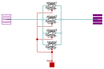
Information
Resistive-inductive model that connects two AC three-phase
unbalanced interfaces with neutral line. This model can be used to represent a
cable in a three-phase unbalanced AC system.
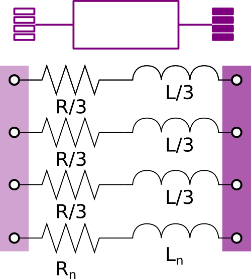
The model represents the lumped impedances as shown in the figure above.
Assuming that the overall cable has a resistance R and an inductance
L, each line has an inductance equal to L/3 and a resistance
equal to R/3.
The resistance and the inductance of the neutral cable are defined separately using the parameters
Rn and Ln.
Extends from Modelica.Electrical.Analog.Interfaces.ConditionalHeatPort (Partial model to include a conditional HeatPort in order to describe the power loss via a thermal network), Buildings.Electrical.AC.ThreePhasesUnbalanced.Interfaces.TwoPort_N (Partial model interface for a two port component with neutral cable).
Parameters
| Type | Name | Default | Description |
|---|
| Boolean | useHeatPort | false | = true, if heatPort is enabled |
| Temperature | T | 293.15 | Fixed device temperature if useHeatPort = false [K] |
| Resistance | R | | Resistance at temperature T_ref [Ohm] |
| Resistance | Rn | | Resistance of neutral cable at temperature T_ref [Ohm] |
| Temperature | T_ref | 298.15 | Reference temperature [K] |
| Temperature | M | 507.65 | Temperature constant (R_actual = R*(M + T_heatPort)/(M + T_ref)) [K] |
| Inductance | L | | Inductance [H] |
| Inductance | Ln | | Inductance of neutral cable [H] |
| Current | i1_start[2] | {0,0} | Initial current phasor of phase 1 (positive if entering from terminal p) [A] |
| Current | i2_start[2] | {0,0} | Initial current phasor of phase 2 (positive if entering from terminal p) [A] |
| Current | i3_start[2] | {0,0} | Initial current phasor of phase 3 (positive if entering from terminal p) [A] |
| Modeling assumption |
| Load | mode | Buildings.Electrical.Types.L... | Type of model (e.g., steady state, dynamic, prescribed power consumption, etc.) |
Connectors
Modelica definition
model TwoPortRL_N
extends Modelica.Electrical.Analog.Interfaces.ConditionalHeatPort;
extends Buildings.Electrical.AC.ThreePhasesUnbalanced.Interfaces.TwoPort_N;
parameter Modelica.Units.SI.Resistance R ;
parameter Modelica.Units.SI.Resistance Rn
;
parameter Modelica.Units.SI.Temperature T_ref=298.15 ;
parameter Modelica.Units.SI.Temperature M=507.65
;
parameter Modelica.Units.SI.Inductance L ;
parameter Modelica.Units.SI.Inductance Ln ;
parameter Modelica.Units.SI.Current i1_start[2]={0,0}
;
parameter Modelica.Units.SI.Current i2_start[2]={0,0}
;
parameter Modelica.Units.SI.Current i3_start[2]={0,0}
;
parameter Buildings.Electrical.Types.Load mode(
min=Buildings.Electrical.Types.Load.FixedZ_steady_state,
max=Buildings.Electrical.Types.Load.FixedZ_dynamic) = Buildings.Electrical.Types.Load.FixedZ_steady_state
;
OnePhase.Lines.TwoPortRL phase1(
final T_ref=T_ref,
final M=M,
final R=R/3,
final L=L/3,
final mode=mode,
final useHeatPort=useHeatPort,
i_start=i1_start) ;
OnePhase.Lines.TwoPortRL phase2(
final T_ref=T_ref,
final M=M,
final R=R/3,
final L=L/3,
final mode=mode,
final useHeatPort=useHeatPort,
i_start=i2_start) ;
OnePhase.Lines.TwoPortRL phase3(
final T_ref=T_ref,
final M=M,
final R=R/3,
final L=L/3,
final mode=mode,
final useHeatPort=useHeatPort,
i_start=i3_start) ;
OnePhase.Lines.TwoPortRL neutral(
final T_ref=T_ref,
final M=M,
final mode=mode,
final useHeatPort=useHeatPort,
final R=Rn,
final L=Ln,
i_start=-i1_start - i2_start - i3_start) ;
equation
LossPower = phase1.LossPower + phase2.LossPower + phase3.LossPower + neutral.LossPower;
connect(terminal_n.phase[1], phase1.terminal_n);
connect(terminal_n.phase[2], phase2.terminal_n);
connect(terminal_n.phase[3], phase3.terminal_n);
connect(phase1.terminal_p, terminal_p.phase[1]);
connect(phase2.terminal_p, terminal_p.phase[2]);
connect(phase3.terminal_p, terminal_p.phase[3]);
connect(phase1.heatPort, heatPort);
connect(phase3.heatPort, heatPort);
connect(phase2.heatPort, heatPort);
connect(neutral.heatPort, heatPort);
connect(neutral.terminal_p, terminal_p.phase[4]);
connect(neutral.terminal_n, terminal_n.phase[4]);
end TwoPortRL_N;
Model of a resistance with two electrical ports
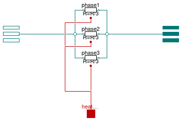
Information
Resistive model that connects two AC three-phase
unbalanced interfaces. This model can be used to represent a
cable in a three-phase unbalanced AC system.
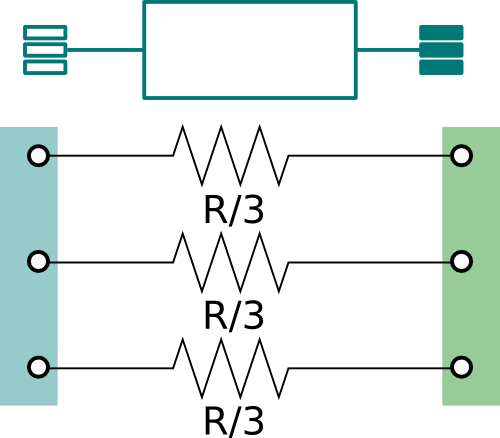
The model represents the lumped resistance as shown in the figure above.
Assuming that the resistance R is the overall resistance of the cable,
each line has a resistance equal to R/3.
Extends from Modelica.Electrical.Analog.Interfaces.ConditionalHeatPort (Partial model to include a conditional HeatPort in order to describe the power loss via a thermal network), Buildings.Electrical.AC.ThreePhasesUnbalanced.Interfaces.TwoPort (Partial model interface for a two port component without neutral cable).
Parameters
| Type | Name | Default | Description |
|---|
| Boolean | useHeatPort | false | = true, if heatPort is enabled |
| Temperature | T | 293.15 | Fixed device temperature if useHeatPort = false [K] |
| Temperature | T_ref | 298.15 | Reference temperature [K] |
| Temperature | M | 507.65 | Temperature constant (R_actual = R*(M + T_heatPort)/(M + T_ref)) [K] |
| Resistance | R | | Resistance at temperature T_ref [Ohm] |
Connectors
Modelica definition
model TwoPortResistance
extends Modelica.Electrical.Analog.Interfaces.ConditionalHeatPort;
extends Buildings.Electrical.AC.ThreePhasesUnbalanced.Interfaces.TwoPort;
parameter Modelica.Units.SI.Temperature T_ref=298.15 ;
parameter Modelica.Units.SI.Temperature M=507.65
;
parameter Modelica.Units.SI.Resistance R ;
OnePhase.Lines.TwoPortResistance phase1(
final T_ref=T_ref,
final M=M,
final R=R/3,
final useHeatPort=useHeatPort) ;
OnePhase.Lines.TwoPortResistance phase2(
final T_ref=T_ref,
final M=M,
final R=R/3,
final useHeatPort=useHeatPort) ;
OnePhase.Lines.TwoPortResistance phase3(
final T_ref=T_ref,
final M=M,
final R=R/3,
final useHeatPort=useHeatPort) ;
equation
LossPower = phase1.LossPower + phase2.LossPower + phase3.LossPower;
connect(terminal_n.phase[1], phase1.terminal_n);
connect(terminal_n.phase[2], phase2.terminal_n);
connect(terminal_n.phase[3], phase3.terminal_n);
connect(phase1.terminal_p, terminal_p.phase[1]);
connect(phase2.terminal_p, terminal_p.phase[2]);
connect(phase3.terminal_p, terminal_p.phase[3]);
connect(phase1.heatPort, heatPort);
connect(phase3.heatPort, heatPort);
connect(phase2.heatPort, heatPort);
end TwoPortResistance;
Model of a resistance with two electrical ports and neutral cable
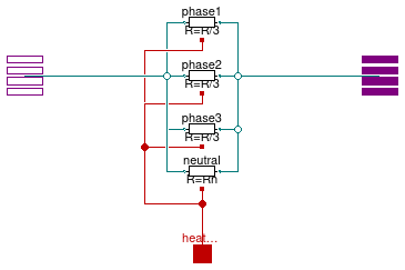
Information
Resistive model that connects two AC three-phase
unbalanced interfaces with neutral line. This model can be used to represent a
cable in a three-phase unbalanced AC system.
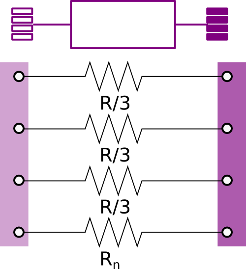
The model represents the lumped resistance as shown in the figure above.
Assuming that the resistance R is the overall resistance of the cable,
each line has a resistance equal to R/3.
The resistance of the neutral cable is defined separately using the parameter
Rn.
Extends from Modelica.Electrical.Analog.Interfaces.ConditionalHeatPort (Partial model to include a conditional HeatPort in order to describe the power loss via a thermal network), Buildings.Electrical.AC.ThreePhasesUnbalanced.Interfaces.TwoPort_N (Partial model interface for a two port component with neutral cable).
Parameters
| Type | Name | Default | Description |
|---|
| Boolean | useHeatPort | false | = true, if heatPort is enabled |
| Temperature | T | 293.15 | Fixed device temperature if useHeatPort = false [K] |
| Temperature | T_ref | 298.15 | Reference temperature [K] |
| Temperature | M | 507.65 | Temperature constant (R_actual = R*(M + T_heatPort)/(M + T_ref)) [K] |
| Resistance | R | | Resistance at temperature T_ref [Ohm] |
| Resistance | Rn | | Resistance of neutral cable at temperature T_ref [Ohm] |
Connectors
Modelica definition
model TwoPortResistance_N
extends Modelica.Electrical.Analog.Interfaces.ConditionalHeatPort;
extends Buildings.Electrical.AC.ThreePhasesUnbalanced.Interfaces.TwoPort_N;
parameter Modelica.Units.SI.Temperature T_ref=298.15 ;
parameter Modelica.Units.SI.Temperature M=507.65
;
parameter Modelica.Units.SI.Resistance R ;
parameter Modelica.Units.SI.Resistance Rn
;
OnePhase.Lines.TwoPortResistance phase1(
final T_ref=T_ref,
final M=M,
final R=R/3,
final useHeatPort=useHeatPort) ;
OnePhase.Lines.TwoPortResistance phase2(
final T_ref=T_ref,
final M=M,
final R=R/3,
final useHeatPort=useHeatPort) ;
OnePhase.Lines.TwoPortResistance phase3(
final T_ref=T_ref,
final M=M,
final R=R/3,
final useHeatPort=useHeatPort) ;
OnePhase.Lines.TwoPortResistance neutral(
final T_ref=T_ref,
final M=M,
final useHeatPort=useHeatPort,
final R=Rn) ;
equation
LossPower = phase1.LossPower + phase2.LossPower + phase3.LossPower + neutral.LossPower;
connect(terminal_n.phase[1], phase1.terminal_n);
connect(terminal_n.phase[2], phase2.terminal_n);
connect(terminal_n.phase[3], phase3.terminal_n);
connect(phase1.terminal_p, terminal_p.phase[1]);
connect(phase2.terminal_p, terminal_p.phase[2]);
connect(phase3.terminal_p, terminal_p.phase[3]);
connect(phase1.heatPort, heatPort);
connect(phase3.heatPort, heatPort);
connect(phase2.heatPort, heatPort);
connect(neutral.heatPort, heatPort);
connect(neutral.terminal_p, terminal_p.phase[4]);
connect(neutral.terminal_n, terminal_n.phase[4]);
end TwoPortResistance_N;
 Buildings.Electrical.AC.ThreePhasesUnbalanced.Lines.Line
 Buildings.Electrical.AC.ThreePhasesUnbalanced.Lines.Line_N
 Buildings.Electrical.AC.ThreePhasesUnbalanced.Lines.Network
 Buildings.Electrical.AC.ThreePhasesUnbalanced.Lines.Network_N
 Buildings.Electrical.AC.ThreePhasesUnbalanced.Lines.TwoPortInductance
 Buildings.Electrical.AC.ThreePhasesUnbalanced.Lines.TwoPortInductance_N
 Buildings.Electrical.AC.ThreePhasesUnbalanced.Lines.TwoPortMatrixRL
 Buildings.Electrical.AC.ThreePhasesUnbalanced.Lines.TwoPortMatrixRLC_N
 Buildings.Electrical.AC.ThreePhasesUnbalanced.Lines.TwoPortRL
 Buildings.Electrical.AC.ThreePhasesUnbalanced.Lines.TwoPortRLC
 Buildings.Electrical.AC.ThreePhasesUnbalanced.Lines.TwoPortRLC_N
 Buildings.Electrical.AC.ThreePhasesUnbalanced.Lines.TwoPortRL_N
 Buildings.Electrical.AC.ThreePhasesUnbalanced.Lines.TwoPortResistance
 Buildings.Electrical.AC.ThreePhasesUnbalanced.Lines.TwoPortResistance_N