Buildings.Experimental.DHC.EnergyTransferStations.Combined.Generation5
Package of models for fifth generation DHC energy transfer stations
Information
This package contains models for energy transfer stations used in fifth generation district heating and cooling systems.
Extends from Modelica.Icons.VariantsPackage (Icon for package containing variants).
Package Content
| Name | Description |
|---|---|
| ETS model for 5GDHC systems with heat recovery chiller and optional borefield | |
| Model of a substation with heat pump and compressor-less cooling | |
| Package of control blocks for fifth generation DHC ETS | |
| Package of models for subsystems of fifth generation DHC ETS | |
| Example models integrating multiple components | |
| Collection of validation models | |
| Package with base classes |
 Buildings.Experimental.DHC.EnergyTransferStations.Combined.Generation5.ChillerBorefield
ETS model for 5GDHC systems with heat recovery chiller and optional borefield

Information
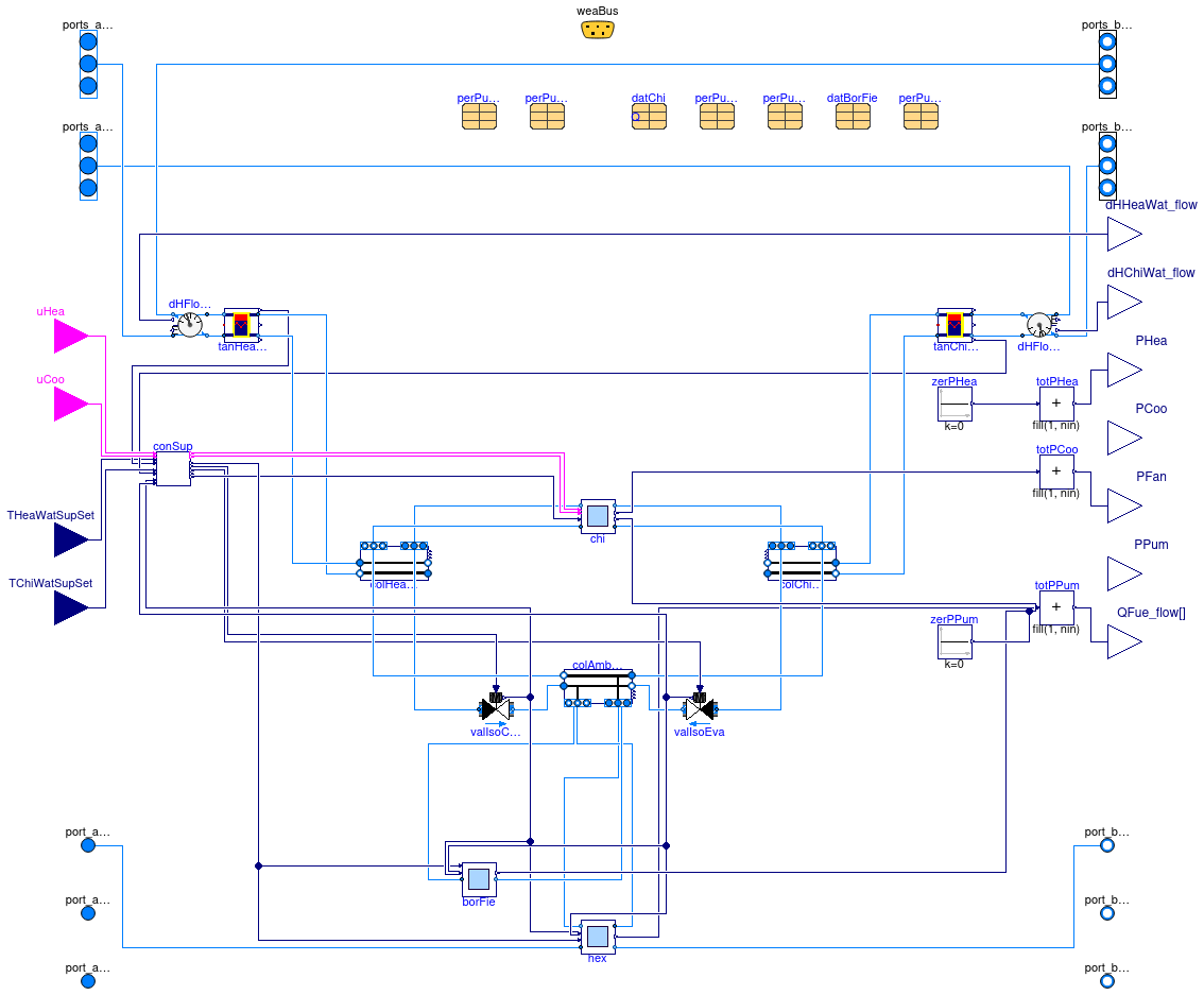
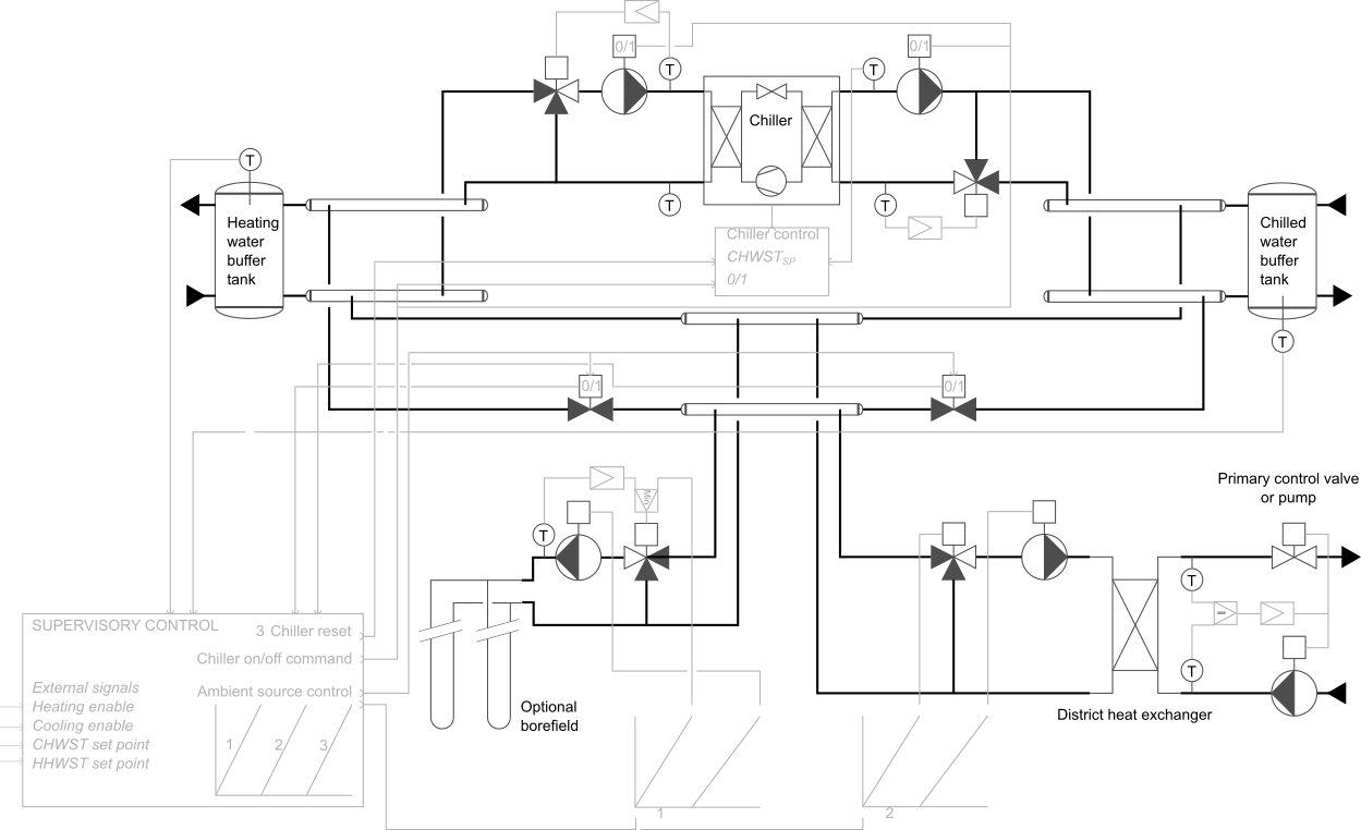
This model represents an energy transfer station as illustrated in the schematics below.
- The heating and cooling functions are provided by a heat recovery chiller, see Buildings.Experimental.DHC.EnergyTransferStations.Combined.Generation5.Subsystems.Chiller for the operating principles and modeling assumptions. The condenser and evaporator loops are equipped with constant speed pumps.
- The supervisory controller ensures the load balancing between the condenser side and the evaporator side of the chiller by controlling in sequence an optional geothermal borefield (priority system), the district heat exchanger (second priority system), and ultimately the chiller, by resetting down the chilled water supply temperature, see Buildings.Experimental.DHC.EnergyTransferStations.Combined.Generation5.Controls.Supervisory for a detailed description. The borefield and district heat exchanger loops are equipped with variable speed pumps modulated by the supervisory controller.
Note that the heating and cooling enable signals (uHea and uCoo)
connected to this model should be switched to false when the
building has no corresponding demand (e.g., based on the requests yielded by
the terminal unit controllers, in conjunction with a schedule).
This will significantly improve the system performance as it is a
necessary condition for the chiller to be operated at a lower lift, see
Buildings.Experimental.DHC.EnergyTransferStations.Combined.Generation5.Controls.Reset.

Extends from BaseClasses.PartialParallel (Partial ETS model with district heat exchanger and parallel connection of production systems).
Parameters
| Type | Name | Default | Description |
|---|---|---|---|
| replaceable package MediumSer | Water | Service side medium | |
| replaceable package MediumSerHea_a | Water | Service side medium at heating inlet | |
| replaceable package MediumBui | Water | Building side medium | |
| Generic | fue[nFue] | Fuel type | |
| ConnectionConfiguration | conCon | EnergyTransferStations.Types... | District connection configuration |
| Integer | nSysHea | 1 | Number of heating systems |
| Integer | nSysCoo | nSysHea | Number of cooling systems |
| Integer | nSouAmb | if have_borFie then 2 else 1 | Number of ambient sources |
| Boolean | have_borFie | false | Set to true in case a borefield is used in addition of the district HX |
| Configuration | |||
| Boolean | have_hotWat | false | Set to true if the ETS supplies hot water |
| Boolean | have_fan | false | Set to true if fan power is computed |
| Boolean | have_eleHea | false | Set to true if the ETS has electric heating system |
| Integer | nFue | 0 | Number of fuel types (0 means no combustion system) |
| Boolean | have_eleCoo | true | Set to true if the ETS has electric cooling system |
| Boolean | have_weaBus | false | Set to true to use a weather bus |
| Nominal condition | |||
| HeatFlowRate | QHeaWat_flow_nominal | 0 | Nominal capacity of heating system (>=0) [W] |
| HeatFlowRate | QHotWat_flow_nominal | 0 | Nominal capacity of hot water production system (>=0) [W] |
| HeatFlowRate | QChiWat_flow_nominal | 0 | Nominal capacity of cooling system (<=0) [W] |
| PressureDifference | dpValIso_nominal | 2E3 | Nominal pressure drop of ambient circuit isolation valves [Pa] |
| District heat exchanger | |||
| PressureDifference | dp1Hex_nominal | Nominal pressure drop across heat exchanger on district side [Pa] | |
| PressureDifference | dp2Hex_nominal | Nominal pressure drop across heat exchanger on building side [Pa] | |
| HeatFlowRate | QHex_flow_nominal | Nominal heat flow rate through heat exchanger (from district to building) [W] | |
| Temperature | T_a1Hex_nominal | Nominal water inlet temperature on district side [K] | |
| Temperature | T_b1Hex_nominal | Nominal water outlet temperature on district side [K] | |
| Temperature | T_a2Hex_nominal | Nominal water inlet temperature on building side [K] | |
| Temperature | T_b2Hex_nominal | Nominal water outlet temperature on building side [K] | |
| TemperatureDifference | dT1HexSet[2] | abs(T_b1Hex_nominal - T_a1He... | Primary side deltaT set point schedule (index 1 for heat rejection) [K] |
| Real | spePum1HexMin | 0.1 | Heat exchanger primary pump minimum speed (fractional) [1] |
| Real | yVal1HexMin | 0.1 | Minimum valve opening for temperature measurement (fractional) [1] |
| Real | spePum2HexMin | 0.1 | Heat exchanger secondary pump minimum speed (fractional) [1] |
| Generic | perPum1Hex | redeclare parameter Building... | Record with performance data for primary pump |
| Generic | perPum2Hex | redeclare parameter Building... | Record with performance data for secondary pump |
| Buffer Tank | |||
| Volume | VTanHeaWat | datChi.PLRMin*datChi.mCon_fl... | Heating water tank volume [m3] |
| Length | hTanHeaWat | (VTanHeaWat*16/Modelica.Cons... | Heating water tank height (assuming twice the diameter) [m] |
| Length | dInsTanHeaWat | 0.1 | Heating water tank insulation thickness [m] |
| Volume | VTanChiWat | datChi.PLRMin*datChi.mEva_fl... | Chilled water tank volume [m3] |
| Length | hTanChiWat | (VTanChiWat*16/Modelica.Cons... | Chilled water tank height (without insulation) [m] |
| Length | dInsTanChiWat | 0.1 | Chilled water tank insulation thickness [m] |
| Integer | nSegTan | 3 | Number of volume segments for tanks |
| Chiller | |||
| PressureDifference | dpCon_nominal | Nominal pressure drop accross condenser [Pa] | |
| PressureDifference | dpEva_nominal | Nominal pressure drop accross evaporator [Pa] | |
| Generic | datChi | redeclare parameter Fluid.Ch... | Chiller performance data |
| Generic | perPumCon | perPumCon(motorCooledByFluid... | Record with performance data for condenser pump |
| Generic | perPumEva | perPumEva(motorCooledByFluid... | Record with performance data for evaporator pump |
| Chiller | chi | chi(redeclare final package ... | Chiller |
| Borefield | |||
| Temperature | TBorWatEntMax | 313.15 | Maximum value of borefield water entering temperature [K] |
| Real | spePumBorMin | 0.1 | Borefield pump minimum speed [1] |
| Pressure | dpBorFie_nominal | 5E4 | Pressure losses for the entire borefield (control valve excluded) [Pa] |
| Example | datBorFie | redeclare parameter Fluid.Ge... | Borefield parameters |
| Generic | perPumBorFie | perPumBorFie(motorCooledByFl... | Record with performance data for borefield pump |
| Borefield | borFie | borFie(redeclare final packa... | Borefield |
| Supervisory controller | |||
| SimpleController | controllerType | Buildings.Controls.OBC.CDL.T... | Type of controller |
| Real | kHot | 0.05 | Gain of controller on hot side |
| Real | kCol | 0.1 | Gain of controller on cold side |
| Time | TiHot | 300 | Time constant of integrator block on hot side [s] |
| Time | TiCol | 120 | Time constant of integrator block on cold side [s] |
| Temperature | THeaWatSupSetMin | datChi.TConEntMin + 5 | Minimum value of heating water supply temperature set point [K] |
| Temperature | TChiWatSupSetMin | datChi.TEvaLvgMin | Minimum value of chilled water supply temperature set point [K] |
| Assumptions | |||
| Boolean | allowFlowReversalSer | false | Set to true to allow flow reversal on service side |
| Boolean | allowFlowReversalBui | false | Set to true to allow flow reversal on building side |
Connectors
| Type | Name | Description |
|---|---|---|
| FluidPorts_a | ports_aHeaWat[nPorts_aHeaWat] | Fluid connectors for heating water return (from building) |
| FluidPorts_b | ports_bHeaWat[nPorts_bHeaWat] | Fluid connectors for heating water supply (to building) |
| FluidPorts_a | ports_aChiWat[nPorts_aChiWat] | Fluid connectors for chilled water return (from building) |
| FluidPorts_b | ports_bChiWat[nPorts_bChiWat] | Fluid connectors for chilled water supply (to building) |
| FluidPort_a | port_aSerAmb | Fluid connector for ambient water service supply line |
| FluidPort_b | port_bSerAmb | Fluid connector for ambient water service return line |
| FluidPort_a | port_aSerHea | Fluid connector for heating service supply line |
| FluidPort_b | port_bSerHea | Fluid connector for heating service return line |
| FluidPort_a | port_aSerCoo | Fluid connector for cooling service supply line |
| FluidPort_b | port_bSerCoo | Fluid connector for cooling service return line |
| output RealOutput | PHea | Power drawn by heating system [W] |
| output RealOutput | PCoo | Power drawn by cooling system [W] |
| output RealOutput | PFan | Power drawn by fan motors [W] |
| output RealOutput | PPum | Power drawn by pump motors [W] |
| output RealOutput | QFue_flow[nFue] | Fuel energy input rate [W] |
| Bus | weaBus | Weather data bus |
| input BooleanInput | uHea | Heating enable signal |
| input BooleanInput | uCoo | Cooling enable signal |
| input RealInput | THeaWatSupSet | Heating water supply temperature set point [K] |
| input RealInput | TChiWatSupSet | Chilled water supply temperature set point [K] |
| output RealOutput | dHHeaWat_flow | Heating water distributed energy flow rate [W] |
| output RealOutput | dHChiWat_flow | Chilled water distributed energy flow rate [W] |
Modelica definition
 Buildings.Experimental.DHC.EnergyTransferStations.Combined.Generation5.HeatPumpHeatExchanger
Model of a substation with heat pump and compressor-less cooling

Information
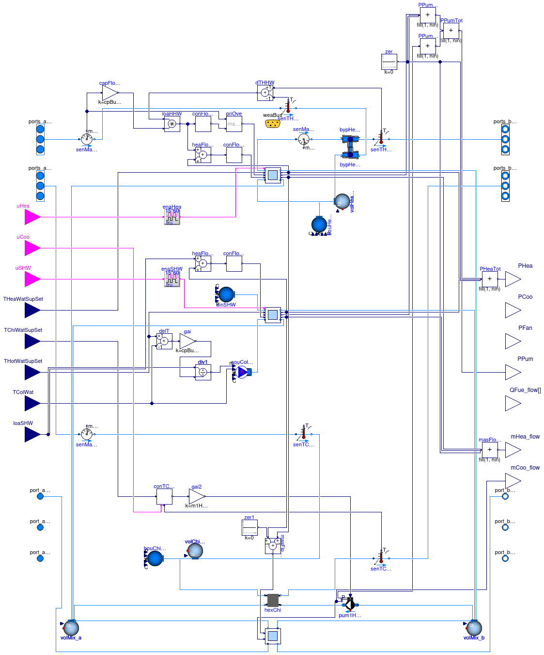
This model represents an energy transfer station as described in Sommer (2020).
- The cooling function is provided in a compressor-less mode by a heat exchanger connected to the service line. The chilled water is typically produced at high temperature and distributed to radiant cooling systems, for instance at 19°C.
-
The heating functions are provided by water-to-water heat pumps.
-
By default the condenser and evaporator loops are operated
with variable mass flow rate, with a lower limit specified by the ratio
ratFloMin. The model can also represent constant flow condenser and evaporator loops by settinghave_varFloConandhave_varFloEvatofalse. - The evaporator water is supplied by mixing the flow rate from the direct connection to the service line to the flow rate from the primary side of the cooling heat exchanger. The hydronic arrangement modeled in Buildings.Experimental.DHC.EnergyTransferStations.Combined.Generation5.Subsystems.SwitchBox ensures that the resulting fluid stream in the service line always flows in the same direction.
- The heating hot water is typically produced at low temperature, for instance 40°C.
-
By default the condenser and evaporator loops are operated
with variable mass flow rate, with a lower limit specified by the ratio
Controls
Heating (resp. cooling) is enabled based on the input signal uHea
(resp. uCoo) which is held for 15 minutes, meaning that,
when enabled, the mode remains active for at least 15 minutes and,
when disabled, the mode cannot be enabled again for at least 15 minutes.
The heating and cooling enable signals should be computed externally based
on a schedule (to lock out the system during off-hours), ideally in conjunction
with the number of requests yielded by the terminal unit controllers, or any
other signal representative of the load.
When enabled,
- the heat pumps and the evaporator and condenser water pumps are controlled based on the principles described in Buildings.Experimental.DHC.EnergyTransferStations.Combined.Generation5.Subsystems.HeatPump. The evaporator and condenser water mass flow rates are computed based on the logic described in Buildings.Experimental.DHC.EnergyTransferStations.Combined.Generation5.Controls.PrimaryVariableFlow.
- the cooling heat exchanger primary pump is modulated based on a PI control loop tracking the chilled water supply temperature at the outlet of the heat exchanger secondary side.
Modeling considerations
There is a control volume at each of the two fluid ports that serve as inlet and outlet of the heating and cooling systems. These approximate the dynamics of the substation, and they also generally avoid nonlinear systems of equations if multiple substations are connected to each other.
References
Sommer T., Sulzer M., Wetter M., Sotnikov A., Mennel S., Stettler C. The reservoir network: A new network topology for district heating and cooling. Energy, Volume 199, 15 May 2020, 117418.
Extends from DHC.EnergyTransferStations.BaseClasses.PartialETS (Partial class for modeling an energy transfer station).
Parameters
| Type | Name | Default | Description |
|---|---|---|---|
| replaceable package MediumSer | Water | Service side medium | |
| replaceable package MediumSerHea_a | Water | Service side medium at heating inlet | |
| replaceable package MediumBui | Water | Building side medium | |
| Generic | fue[nFue] | Fuel type | |
| Boolean | have_varFloCon | true | Set to true for heat pumps with variable condenser flow |
| Boolean | have_varFloEva | true | Set to true for heat pumps with variable evaporator flow |
| Real | ratFloMin | 0.3 | Minimum condenser or evaporator mass flow rate (ratio to nominal) [1] |
| Configuration | |||
| DistrictSystemType | typ | DHC.Types.DistrictSystemType... | Type of district system |
| Boolean | have_heaWat | true | Set to true if the ETS supplies heating water |
| Boolean | have_hotWat | false | Set to true if the ETS supplies hot water |
| Boolean | have_chiWat | true | Set to true if the ETS supplies chilled water |
| Boolean | have_fan | false | Set to true if fan power is computed |
| Boolean | have_pum | true | Set to true if pump power is computed |
| Boolean | have_eleHea | true | Set to true if the ETS has electric heating system |
| Integer | nFue | 0 | Number of fuel types (0 means no combustion system) |
| Boolean | have_eleCoo | false | Set to true if the ETS has electric cooling system |
| Boolean | have_weaBus | false | Set to true to use a weather bus |
| Nominal condition | |||
| HeatFlowRate | QHeaWat_flow_nominal | 0 | Nominal capacity of heating system (>=0) [W] |
| HeatFlowRate | QHotWat_flow_nominal | 0 | Nominal capacity of hot water production system (>=0) [W] |
| HeatFlowRate | QChiWat_flow_nominal | 0 | Nominal capacity of cooling system (<=0) [W] |
| TemperatureDifference | dT_nominal | 5 | Water temperature drop/increase accross load and source-side HX (always positive) [K] |
| Temperature | THeaWatSup_nominal | 313.15 | Heating water supply temperature [K] |
| Temperature | THotWatSup_nominal | 336.15 | Hot water supply temperature [K] |
| Temperature | TColWat_nominal | 288.15 | Cold water temperature (for hot water production) [K] |
| Pressure | dp_nominal | 50000 | Pressure difference at nominal flow rate (for each flow leg) [Pa] |
| Real | COPHeaWat_nominal | COP of heat pump for heating water production [1] | |
| Real | COPHotWat_nominal | COP of heat pump for hot water production [1] | |
| DHC system | |||
| Temperature | TDisWatMin | District water minimum temperature [K] | |
| Temperature | TDisWatMax | District water maximum temperature [K] | |
| Nominal conditions | |||
| Temperature | TChiWatSup_nominal | 291.15 | Chilled water supply temperature [K] |
| Assumptions | |||
| Boolean | allowFlowReversalSer | false | Set to true to allow flow reversal on service side |
| Boolean | allowFlowReversalBui | false | Set to true to allow flow reversal on building side |
| Dynamics | |||
| Dynamics | mixingVolumeEnergyDynamics | Modelica.Fluid.Types.Dynamic... | Formulation of energy balance for mixing volume at inlet and outlet |
Connectors
| Type | Name | Description |
|---|---|---|
| FluidPorts_a | ports_aHeaWat[nPorts_aHeaWat] | Fluid connectors for heating water return (from building) |
| FluidPorts_b | ports_bHeaWat[nPorts_bHeaWat] | Fluid connectors for heating water supply (to building) |
| FluidPorts_a | ports_aChiWat[nPorts_aChiWat] | Fluid connectors for chilled water return (from building) |
| FluidPorts_b | ports_bChiWat[nPorts_bChiWat] | Fluid connectors for chilled water supply (to building) |
| FluidPort_a | port_aSerAmb | Fluid connector for ambient water service supply line |
| FluidPort_b | port_bSerAmb | Fluid connector for ambient water service return line |
| FluidPort_a | port_aSerHea | Fluid connector for heating service supply line |
| FluidPort_b | port_bSerHea | Fluid connector for heating service return line |
| FluidPort_a | port_aSerCoo | Fluid connector for cooling service supply line |
| FluidPort_b | port_bSerCoo | Fluid connector for cooling service return line |
| output RealOutput | PHea | Power drawn by heating system [W] |
| output RealOutput | PCoo | Power drawn by cooling system [W] |
| output RealOutput | PFan | Power drawn by fan motors [W] |
| output RealOutput | PPum | Power drawn by pump motors [W] |
| output RealOutput | QFue_flow[nFue] | Fuel energy input rate [W] |
| Bus | weaBus | Weather data bus |
| input BooleanInput | uCoo | Cooling enable signal |
| input BooleanInput | uHea | Heating enable signal |
| input BooleanInput | uSHW | SHW production enable signal |
| input RealInput | THeaWatSupSet | Heating water supply temperature set point [K] |
| input RealInput | THotWatSupSet | Service hot water supply temperature set point [K] |
| input RealInput | TColWat | Cold water temperature [K] |
| input RealInput | loaSHW | Service hot water load [W] |
| input RealInput | TChiWatSupSet | Chilled water supply temperature set point [K] |
| output RealOutput | mHea_flow | District water mass flow rate used for heating service [kg/s] |
| output RealOutput | mCoo_flow | District water mass flow rate used for cooling service [kg/s] |
