Buildings.Experimental.DHC.EnergyTransferStations.BaseClasses
Package with base classes
Information
This package contains base classes that are used to construct the classes in Buildings.Experimental.DHC.EnergyTransferStations.
Extends from Modelica.Icons.BasesPackage (Icon for packages containing base classes).
Package Content
| Name | Description |
|---|---|
| Model of a collector/distributor with zero pressure drop between connections | |
| Model of a lossless connection to a collector/distributor | |
| Fluid junction with zero pressure drop | |
| Partial class for modeling an energy transfer station | |
| Pump with prescribed mass flow rate | |
| Stratified buffer tank model | |
| Coordinates of evenly distributed boreholes given the number of boreholes | |
| Collection of validation models |
 Buildings.Experimental.DHC.EnergyTransferStations.BaseClasses.CollectorDistributor
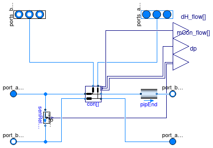
Model of a collector/distributor with zero pressure drop between connections
Information
This model represents a collector/distributor which connects
nCon hydronic circuits in parallel.
The pressure drop between each connection is assumed negligible
compared to the pressure drop in each circuit, and is set to zero
in the model.
By default,
-
there is no bypass flow (which can be added later by connecting
the ports
port_bDisSupandport_aDisRet), -
the nominal distribution mass flow rate
mDis_flow_nominalis equal to the sum of the nominal mass flow rate in each circuit. However, this parameter assigment is not final and it can be set for instance to a higher value to represent a primary overflow in a supply through loop.
Extends from Networks.BaseClasses.PartialDistribution2Pipe (Partial model for two-pipe distribution network).
Parameters
| Type | Name | Default | Description |
|---|---|---|---|
| replaceable package Medium | PartialMedium | Medium model | |
| Integer | nCon | Number of connections | |
| replaceable model Model_pipDis | Fluid.FixedResistances.Lossl... | Model for distribution pipe | |
| Integer | iConDpSen | -1 | Index of the connection where the pressure drop is measured |
| Boolean | show_entFlo | false | Set to true to output enthalpy flow rate difference at each connection |
| Nominal condition | |||
| MassFlowRate | mDis_flow_nominal | sum(mCon_flow_nominal) | Nominal mass flow rate in the distribution line before the first connection [kg/s] |
| MassFlowRate | mCon_flow_nominal[nCon] | Nominal mass flow rate in each connection line [kg/s] | |
| MassFlowRate | mEnd_flow_nominal | mDis_flow_nominal | Nominal mass flow rate in the end of the distribution line [kg/s] |
| MassFlowRate | mDisCon_flow_nominal[nCon] | fill(mDis_flow_nominal, nCon) | Nominal mass flow rate in the distribution line before each connection [kg/s] |
| Assumptions | |||
| Boolean | allowFlowReversal | true | = true to allow flow reversal, false restricts to design direction (port_a -> port_b) |
| Dynamics | |||
| Equations | |||
| Dynamics | energyDynamics | Modelica.Fluid.Types.Dynamic... | Type of energy balance: dynamic (3 initialization options) or steady state |
| Nominal condition | |||
| Time | tau | 10 | Time constant at nominal flow for dynamic energy and momentum balance [s] |
Connectors
| Type | Name | Description |
|---|---|---|
| FluidPorts_a | ports_aCon[nCon] | Connection return ports |
| FluidPorts_b | ports_bCon[nCon] | Connection supply ports |
| FluidPort_a | port_aDisSup | Distribution supply inlet port |
| FluidPort_b | port_bDisSup | Distribution supply outlet port |
| replaceable model Model_pipDis | Model for distribution pipe | |
| FluidPort_b | port_bDisRet | Distribution return outlet port |
| FluidPort_a | port_aDisRet | Distribution return inlet port |
| output RealOutput | dp | Pressure difference at given location (measured) [Pa] |
| output RealOutput | dH_flow[nCon] | Difference in enthalpy flow rate between connection supply and return [W] |
| output RealOutput | mCon_flow[nCon] | Connection supply mass flow rate (measured) [kg/s] |
Modelica definition
 Buildings.Experimental.DHC.EnergyTransferStations.BaseClasses.Connection2PipeLossless
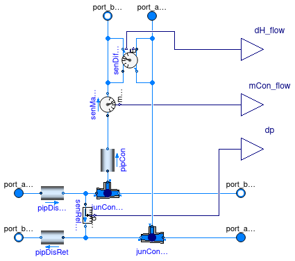
Model of a lossless connection to a collector/distributor
Information
This is a model of a connection for a two-pipe system using a pipe model with no flow resistance, no heat loss and no transport delay.
Extends from Networks.BaseClasses.PartialConnection2Pipe (Partial model for connecting an agent to a two-pipe distribution network).
Parameters
| Type | Name | Default | Description |
|---|---|---|---|
| replaceable package Medium | PartialMedium | Medium model | |
| replaceable model Model_pipDis | Buildings.Fluid.FixedResista... | ||
| replaceable model Model_pipCon | Buildings.Fluid.FixedResista... | ||
| Boolean | show_entFlo | false | Set to true to output enthalpy flow rate difference |
| Nominal condition | |||
| MassFlowRate | mDis_flow_nominal | Nominal mass flow rate in the distribution line [kg/s] | |
| MassFlowRate | mCon_flow_nominal | Nominal mass flow rate in the connection line [kg/s] | |
| Assumptions | |||
| Boolean | allowFlowReversal | false | = true to allow flow reversal, false restricts to design direction (port_a -> port_b) |
| Dynamics | |||
| Equations | |||
| Dynamics | energyDynamics | Modelica.Fluid.Types.Dynamic... | Type of energy balance: dynamic (3 initialization options) or steady state |
| Nominal condition | |||
| Time | tau | 10 | Time constant at nominal flow for dynamic energy and momentum balance [s] |
Connectors
| Type | Name | Description |
|---|---|---|
| replaceable model Model_pipDis | ||
| replaceable model Model_pipCon | ||
| FluidPort_a | port_aDisSup | Distribution supply inlet port |
| FluidPort_b | port_bDisSup | Distribution supply outlet port |
| FluidPort_a | port_aDisRet | Distribution return inlet port |
| FluidPort_b | port_bDisRet | Distribution return outlet port |
| FluidPort_b | port_bCon | Connection supply port |
| FluidPort_a | port_aCon | Connection return port |
| output RealOutput | mCon_flow | Connection supply mass flow rate [kg/s] |
| output RealOutput | dp | Pressure drop accross the connection (measured) [Pa] |
| output RealOutput | dH_flow | Difference in enthalpy flow rate between connection supply and return [W] |
Modelica definition
 Buildings.Experimental.DHC.EnergyTransferStations.BaseClasses.Junction
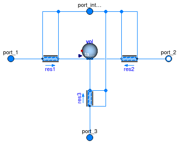
Fluid junction with zero pressure drop
Information
This is a model of a fluid junction with zero pressure drop. By default the model is configured in steady-state.
Extends from Fluid.FixedResistances.Junction (Flow splitter with fixed resistance at each port).
Parameters
| Type | Name | Default | Description |
|---|---|---|---|
| replaceable package Medium | PartialMedium | Medium in the component | |
| Nominal condition | |||
| MassFlowRate | m_flow_nominal[3] | Mass flow rate. Set negative at outflowing ports. [kg/s] | |
| Pressure | dp_nominal[3] | fill(0, 3) | Pressure drop at nominal mass flow rate, set to zero or negative number at outflowing ports. [Pa] |
| Transition to laminar | |||
| Real | deltaM | 0.3 | Fraction of nominal mass flow rate where transition to turbulent occurs |
| Dynamics | |||
| Equations | |||
| Dynamics | energyDynamics | Modelica.Fluid.Types.Dynamic... | Type of energy balance: dynamic (3 initialization options) or steady state |
| Dynamics | massDynamics | energyDynamics | Type of mass balance: dynamic (3 initialization options) or steady state |
| MassFlowRate | mDyn_flow_nominal | sum(abs(m_flow_nominal[:])/3) | Nominal mass flow rate for dynamic momentum and energy balance [kg/s] |
| Nominal condition | |||
| Time | tau | 10 | Time constant at nominal flow for dynamic energy and momentum balance [s] |
| Initialization | |||
| AbsolutePressure | p_start | Medium.p_default | Start value of pressure [Pa] |
| Temperature | T_start | Medium.T_default | Start value of temperature [K] |
| MassFraction | X_start[Medium.nX] | Medium.X_default | Start value of mass fractions m_i/m [kg/kg] |
| ExtraProperty | C_start[Medium.nC] | fill(0, Medium.nC) | Start value of trace substances |
| ExtraProperty | C_nominal[Medium.nC] | fill(1E-2, Medium.nC) | Nominal value of trace substances. (Set to typical order of magnitude.) |
| Advanced | |||
| Boolean | from_dp | false | = true, use m_flow = f(dp) else dp = f(m_flow) |
| PortFlowDirection | portFlowDirection_1 | Modelica.Fluid.Types.PortFlo... | Flow direction for port_1 |
| PortFlowDirection | portFlowDirection_2 | Modelica.Fluid.Types.PortFlo... | Flow direction for port_2 |
| PortFlowDirection | portFlowDirection_3 | Modelica.Fluid.Types.PortFlo... | Flow direction for port_3 |
| Boolean | verifyFlowReversal | false | =true, to assert that the flow does not reverse when portFlowDirection_* does not equal Bidirectional |
| MassFlowRate | m_flow_small | mDyn_flow_nominal*1e-4 | Small mass flow rate for checking flow reversal [kg/s] |
| Boolean | linearized | false | = true, use linear relation between m_flow and dp for any flow rate |
Connectors
| Type | Name | Description |
|---|---|---|
| FluidPort_a | port_1 | First port, typically inlet |
| FluidPort_b | port_2 | Second port, typically outlet |
| FluidPort_a | port_3 | Third port, can be either inlet or outlet |
Modelica definition
 Buildings.Experimental.DHC.EnergyTransferStations.BaseClasses.PartialETS
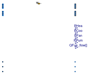
Partial class for modeling an energy transfer station
Information
Partial class to be used for modeling an energy transfer station and optional in-building primary systems.
The connectors to the service lines are configured based on an enumeration
defining the type of district system (CombinedGeneration2to4
by default), see
Buildings.Experimental.DHC.Types.DistrictSystemType.
In case of a heating service line, the model allows for using two
different media at the inlet port port_aSerHea and at the oulet
port port_bSerHea to represent a steam supply and condensate
return.
The connectors to the building distribution systems are configured based
on the Boolean parameters have_heaWat and have_chiWat.
Parameters
| Type | Name | Default | Description |
|---|---|---|---|
| replaceable package MediumSer | Buildings.Media.Water | Service side medium | |
| replaceable package MediumSerHea_a | Buildings.Media.Water | Service side medium at heating inlet | |
| replaceable package MediumBui | Buildings.Media.Water | Building side medium | |
| Generic | fue[nFue] | Fuel type | |
| Configuration | |||
| DistrictSystemType | typ | TypDisSys.CombinedGeneration... | Type of district system |
| Boolean | have_heaWat | false | Set to true if the ETS supplies heating water |
| Boolean | have_hotWat | false | Set to true if the ETS supplies hot water |
| Boolean | have_chiWat | false | Set to true if the ETS supplies chilled water |
| Boolean | have_fan | false | Set to true if fan power is computed |
| Boolean | have_pum | false | Set to true if pump power is computed |
| Boolean | have_eleHea | false | Set to true if the ETS has electric heating system |
| Integer | nFue | 0 | Number of fuel types (0 means no combustion system) |
| Boolean | have_eleCoo | false | Set to true if the ETS has electric cooling system |
| Boolean | have_weaBus | false | Set to true to use a weather bus |
| Nominal condition | |||
| HeatFlowRate | QHeaWat_flow_nominal | 0 | Nominal capacity of heating system (>=0) [W] |
| HeatFlowRate | QHotWat_flow_nominal | 0 | Nominal capacity of hot water production system (>=0) [W] |
| HeatFlowRate | QChiWat_flow_nominal | 0 | Nominal capacity of cooling system (<=0) [W] |
| Assumptions | |||
| Boolean | allowFlowReversalSer | false | Set to true to allow flow reversal on service side |
| Boolean | allowFlowReversalBui | false | Set to true to allow flow reversal on building side |
Connectors
| Type | Name | Description |
|---|---|---|
| replaceable package MediumSer | Service side medium | |
| replaceable package MediumSerHea_a | Service side medium at heating inlet | |
| replaceable package MediumBui | Building side medium | |
| FluidPorts_a | ports_aHeaWat[nPorts_aHeaWat] | Fluid connectors for heating water return (from building) |
| FluidPorts_b | ports_bHeaWat[nPorts_bHeaWat] | Fluid connectors for heating water supply (to building) |
| FluidPorts_a | ports_aChiWat[nPorts_aChiWat] | Fluid connectors for chilled water return (from building) |
| FluidPorts_b | ports_bChiWat[nPorts_bChiWat] | Fluid connectors for chilled water supply (to building) |
| FluidPort_a | port_aSerAmb | Fluid connector for ambient water service supply line |
| FluidPort_b | port_bSerAmb | Fluid connector for ambient water service return line |
| FluidPort_a | port_aSerHea | Fluid connector for heating service supply line |
| FluidPort_b | port_bSerHea | Fluid connector for heating service return line |
| FluidPort_a | port_aSerCoo | Fluid connector for cooling service supply line |
| FluidPort_b | port_bSerCoo | Fluid connector for cooling service return line |
| output RealOutput | PHea | Power drawn by heating system [W] |
| output RealOutput | PCoo | Power drawn by cooling system [W] |
| output RealOutput | PFan | Power drawn by fan motors [W] |
| output RealOutput | PPum | Power drawn by pump motors [W] |
| output RealOutput | QFue_flow[nFue] | Fuel energy input rate [W] |
| Bus | weaBus | Weather data bus |
Modelica definition
 Buildings.Experimental.DHC.EnergyTransferStations.BaseClasses.Pump_m_flow
Pump with prescribed mass flow rate
Information
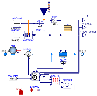
This is a steady-state model of a pump with ideally controlled mass flow rate as input signal, and no heat added to the medium.
Extends from Buildings.Fluid.Movers.FlowControlled_m_flow (Fan or pump with ideally controlled mass flow rate as input signal).
Parameters
| Type | Name | Default | Description |
|---|---|---|---|
| replaceable package Medium | PartialMedium | Medium in the component | |
| Boolean | addPowerToMedium | false | Set to false to avoid any power (=heat and flow work) being added to medium (may give simpler equations) |
| Boolean | nominalValuesDefineDefaultPressureCurve | true | Set to true to avoid warning if m_flow_nominal and dp_nominal are used to construct the default pressure curve |
| MassFlowRate | constantMassFlowRate | m_flow_nominal | Constant pump mass flow rate, used when inputType=Constant [kg/s] |
| MassFlowRate | massFlowRates[:] | m_flow_nominal*{per.speeds[i... | Vector of mass flow rate set points, used when inputType=Stage [kg/s] |
| Nominal condition | |||
| MassFlowRate | m_flow_nominal | m_flow_nominal(final min=Mod... | Nominal mass flow rate [kg/s] |
| PressureDifference | dp_nominal | if rho_default < 500 then 50... | Nominal pressure raise, used for default pressure curve if not specified in record per [Pa] |
| Control | |||
| InputType | inputType | Buildings.Fluid.Types.InputT... | Control input type |
| Dynamics | |||
| Equations | |||
| Dynamics | energyDynamics | Modelica.Fluid.Types.Dynamic... | Type of energy balance: dynamic (3 initialization options) or steady state |
| Dynamics | massDynamics | energyDynamics | Type of mass balance: dynamic (3 initialization options) or steady state |
| Nominal condition | |||
| Time | tau | 1 | Time constant of fluid volume for nominal flow, used if energy or mass balance is dynamic [s] |
| Filtered speed | |||
| Boolean | use_inputFilter | false | = true, if speed is filtered with a 2nd order CriticalDamping filter |
| Time | riseTime | 30 | Rise time of the filter (time to reach 99.6 % of the speed) [s] |
| Init | init | Modelica.Blocks.Types.Init.I... | Type of initialization (no init/steady state/initial state/initial output) |
| Real | y_start | 0 | Initial value of speed [1] |
| MassFlowRate | m_flow_start | 0 | Initial value of mass flow rate [kg/s] |
| Initialization | |||
| AbsolutePressure | p_start | Medium.p_default | Start value of pressure [Pa] |
| Temperature | T_start | Medium.T_default | Start value of temperature [K] |
| MassFraction | X_start[Medium.nX] | Medium.X_default | Start value of mass fractions m_i/m [kg/kg] |
| ExtraProperty | C_start[Medium.nC] | fill(0, Medium.nC) | Start value of trace substances |
| ExtraProperty | C_nominal[Medium.nC] | fill(1E-2, Medium.nC) | Nominal value of trace substances. (Set to typical order of magnitude.) |
| Assumptions | |||
| Boolean | allowFlowReversal | true | = false to simplify equations, assuming, but not enforcing, no flow reversal |
| Advanced | |||
| MassFlowRate | m_flow_small | 1E-4*abs(m_flow_nominal) | Small mass flow rate for regularization of zero flow [kg/s] |
| Diagnostics | |||
| Boolean | show_T | false | = true, if actual temperature at port is computed |
Connectors
| Type | Name | Description |
|---|---|---|
| FluidPort_a | port_a | Fluid connector a (positive design flow direction is from port_a to port_b) |
| FluidPort_b | port_b | Fluid connector b (positive design flow direction is from port_a to port_b) |
| input IntegerInput | stage | Stage input signal for the pressure head |
| output RealOutput | y_actual | Actual normalised pump speed that is used for computations [1] |
| output RealOutput | P | Electrical power consumed [W] |
| HeatPort_a | heatPort | Heat dissipation to environment |
| input RealInput | m_flow_in | Prescribed mass flow rate [kg/s] |
| output RealOutput | m_flow_actual | Actual mass flow rate [kg/s] |
Modelica definition
 Buildings.Experimental.DHC.EnergyTransferStations.BaseClasses.StratifiedTank
Stratified buffer tank model
Information
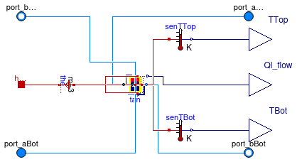
This is a four-port tank model based on Buildings.Fluid.Storage.Stratified which includes the following features.
-
The two fluid ports suffixed with
Topare connected to the fluid volume at the top of the tank. -
The two fluid ports suffixed with
Botare connected to the fluid volume at the bottom of the tank. - A unique heat port is exposed as an external connector. It is meant to provide a uniform temperature boundary condition at the external surface of the tank (outside insulation).
- The model outputs the temperature of the fluid volumes at the top and at the bottom of the tank.
Parameters
| Type | Name | Default | Description |
|---|---|---|---|
| replaceable package Medium | Modelica.Media.Interfaces.Pa... | Medium model | |
| Volume | VTan | Tank volume [m3] | |
| Length | hTan | Height of tank (without insulation) [m] | |
| Length | dIns | Thickness of insulation [m] | |
| ThermalConductivity | kIns | 0.04 | Specific heat conductivity of insulation [W/(m.K)] |
| Integer | nSeg | 3 | Number of volume segments |
| Nominal condition | |||
| MassFlowRate | m_flow_nominal | Nominal mass flow rate [kg/s] | |
Connectors
| Type | Name | Description |
|---|---|---|
| replaceable package Medium | Medium model | |
| FluidPort_a | port_aTop | Inlet fluid port at tank top |
| FluidPort_b | port_bBot | Outlet fluid port at tank bottom |
| FluidPort_a | port_aBot | Inlet fluid port at tank bottom |
| FluidPort_b | port_bTop | Outlet fluid port at tank top |
| output RealOutput | Ql_flow | Heat loss of tank (positive if heat flows from tank to ambient) [W] |
| output RealOutput | TTop | Fluid temperature at tank top [K] |
| output RealOutput | TBot | Fluid temperature at tank bottom [K] |
| HeatPort_a | heaPorAmb | Heat port at interface with ambient (outside insulation) |
Modelica definition
Buildings.Experimental.DHC.EnergyTransferStations.BaseClasses.computeCoordinates
Coordinates of evenly distributed boreholes given the number of boreholes
Information
This function computes the coordinates of boreholes evenly
distributed along the x and y axis,
given the number of boreholes (which must be the square of
an integer).
Inputs
| Type | Name | Default | Description |
|---|---|---|---|
| Integer | nBorHol | Number of boreholes | |
| Distance | dxy | 6 | Distance in x-axis (and y-axis) between borehole axes [m] |
Outputs
| Type | Name | Description |
|---|---|---|
| Distance | cooBor[nBorHol, 2] | Coordinates of boreholes [m] |
