Buildings.Experimental.DHC.CentralPlants.Cooling.Controls

Package of control sequences for cooling plants

Information

This package contains control sequences for central cooling plants.

Extends from Modelica.Icons.VariantsPackage (Icon for package containing variants).

Package Content

Name Description
Buildings.Experimental.DHC.CentralPlants.Cooling.Controls.ChilledWaterBypass ChilledWaterBypass Controller for chilled water bypass valve
Buildings.Experimental.DHC.CentralPlants.Cooling.Controls.ChilledWaterPumpSpeed ChilledWaterPumpSpeed Controller for up to two headered variable speed chilled water pumps
Buildings.Experimental.DHC.CentralPlants.Cooling.Controls.ChillerStage ChillerStage Chiller staging controller for plants with two chillers of the same size
Buildings.Experimental.DHC.CentralPlants.Cooling.Controls.Validation Validation Collection of validation models

Buildings.Experimental.DHC.CentralPlants.Cooling.Controls.ChilledWaterBypass Buildings.Experimental.DHC.CentralPlants.Cooling.Controls.ChilledWaterBypass

Controller for chilled water bypass valve

Buildings.Experimental.DHC.CentralPlants.Cooling.Controls.ChilledWaterBypass

Information

This model implements the chilled water loop bypass valve control logic as follows:

When the plant is on, the PID controller controls the valve opening ratio to reach the scaled mass flow rate setpoint.

The setpoint is mMin_flow multiplied by the number of chillers that are on. mMin_flow is the minimum mass flow rate required by one chiller.

This control sequence assumes that all the chillers are identical and the cooling load is evenly split between all of the chillers that are on.

Extends from Modelica.Blocks.Icons.Block (Basic graphical layout of input/output block).

Parameters

TypeNameDefaultDescription
IntegernumChi Number of chillers
MassFlowRatemMin_flow Minimum mass flow rate of single chiller [kg/s]
Realk0.06Gain of controller
TimeTi60Time constant of Integrator block [s]
SimpleControllercontrollerTypeModelica.Blocks.Types.Simple...Type of controller

Connectors

TypeNameDescription
input BooleanInputchiOn[numChi]On signals of the chillers
input RealInputmFloBypChilled water bypass loop mass flow rate [kg/s]
output RealOutputyBypass valve opening ratio

Modelica definition

model ChilledWaterBypass "Controller for chilled water bypass valve" extends Modelica.Blocks.Icons.Block; parameter Integer numChi( min=1) "Number of chillers"; parameter Modelica.SIunits.MassFlowRate mMin_flow "Minimum mass flow rate of single chiller"; parameter Real k(min=0) = 0.06 "Gain of controller"; parameter Modelica.SIunits.Time Ti(min=Modelica.Constants.small)=60 "Time constant of Integrator block"; parameter Modelica.Blocks.Types.SimpleController controllerType= Modelica.Blocks.Types.SimpleController.PI "Type of controller"; Modelica.Blocks.Interfaces.BooleanInput chiOn[numChi] "On signals of the chillers"; Modelica.Blocks.Interfaces.RealInput mFloByp(final unit="kg/s") "Chilled water bypass loop mass flow rate"; Modelica.Blocks.Interfaces.RealOutput y "Bypass valve opening ratio"; Buildings.Controls.OBC.CDL.Continuous.PIDWithReset bypValCon( controllerType=controllerType, final k=k, final Ti=Ti, yMin=0.01, y_reset=0) "Chilled water bypass valve controller"; Modelica.Blocks.Math.BooleanToInteger booToInt[numChi] "Boolean signal to integer"; Buildings.Controls.OBC.CDL.Integers.GreaterThreshold intGreThr "Greater than zero"; Buildings.Controls.OBC.CDL.Integers.MultiSum numChiOn(nin=numChi) "Number of chillers on"; Buildings.Controls.OBC.CDL.Conversions.IntegerToReal intToRea "Integer to real"; Modelica.Blocks.Math.Gain mFloSetSca(k=1/numChi) "Normalize mass flowrate setpoint"; Modelica.Blocks.Math.Gain mFloBypSca(k=1/(numChi*mMin_flow)) "Normalize the measured mass flowrate"; equation connect(chiOn, booToInt.u); connect(booToInt.y, numChiOn.u); connect(numChiOn.y, intGreThr.u); connect(intGreThr.y, bypValCon.trigger); connect(numChiOn.y, intToRea.u); connect(bypValCon.y, y); connect(intToRea.y, mFloSetSca.u); connect(mFloSetSca.y, bypValCon.u_s); connect(mFloByp, mFloBypSca.u); connect(mFloBypSca.y, bypValCon.u_m); connect(y, y); end ChilledWaterBypass;

Buildings.Experimental.DHC.CentralPlants.Cooling.Controls.ChilledWaterPumpSpeed Buildings.Experimental.DHC.CentralPlants.Cooling.Controls.ChilledWaterPumpSpeed

Controller for up to two headered variable speed chilled water pumps

Buildings.Experimental.DHC.CentralPlants.Cooling.Controls.ChilledWaterPumpSpeed

Information

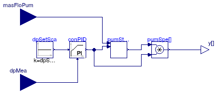
This model implements the control logic for variable speed pumps. The staging of pumps is implemented through an instance of Buildings.Applications.DataCenters.ChillerCooled.Controls.VariableSpeedPumpStagee.

The pump speed is controlled to maintain the pressure difference setpoint through a PID controller.

The model inputs are the measured chilled water mass flow rate masFloPum and the pressure difference dpMea at a reference point from the demand side. The output y is a vector of pump speeds.

The model currently only supports the control of up to two variable speed pumps.

Extends from Modelica.Blocks.Icons.Block (Basic graphical layout of input/output block).

Parameters

TypeNameDefaultDescription
PressureDifferencedpSetPoi Pressure difference setpoint [Pa]
TimetWai Waiting time [s]
MassFlowRatem_flow_nominal Nominal mass flow rate of single chilled water pump [kg/s]
RealminSpe0.05Minimum speed ratio required by chilled water pumps [1]
MassFlowRatecriPoiFlo0.7*m_flow_nominalCritcal point of flowrate for switching pump on or off [kg/s]
MassFlowRatedeaBanFlo0.1*m_flow_nominalDeadband for critical point of flowrate [kg/s]
RealcriPoiSpe0.5Critical point of speed signal for switching on or off
RealdeaBanSpe0.3Deadband for critical point of speed signal
Speed Controller
SimpleControllercontrollerTypeModelica.Blocks.Types.Simple...Type of pump speed controller
Realk1Gain of controller [1]
TimeTi60Time constant of Integrator block [s]
TimeTd0.1Time constant of Derivative block [s]

Connectors

TypeNameDescription
input RealInputmasFloPumTotal mass flowrate of chilled water pumps [kg/s]
input RealInputdpMeaMeasured pressure difference [Pa]
output RealOutputy[numPum]Pump speed signal [1]

Modelica definition

model ChilledWaterPumpSpeed "Controller for up to two headered variable speed chilled water pumps" extends Modelica.Blocks.Icons.Block; parameter Modelica.SIunits.PressureDifference dpSetPoi( displayUnit="Pa") "Pressure difference setpoint"; parameter Modelica.SIunits.Time tWai "Waiting time"; parameter Modelica.SIunits.MassFlowRate m_flow_nominal "Nominal mass flow rate of single chilled water pump"; parameter Real minSpe( final unit="1", final min=0, final max=1)=0.05 "Minimum speed ratio required by chilled water pumps"; parameter Modelica.SIunits.MassFlowRate criPoiFlo=0.7*m_flow_nominal "Critcal point of flowrate for switching pump on or off"; parameter Modelica.SIunits.MassFlowRate deaBanFlo=0.1*m_flow_nominal "Deadband for critical point of flowrate"; parameter Real criPoiSpe=0.5 "Critical point of speed signal for switching on or off"; parameter Real deaBanSpe=0.3 "Deadband for critical point of speed signal"; parameter Modelica.Blocks.Types.SimpleController controllerType= Modelica.Blocks.Types.SimpleController.PI "Type of pump speed controller"; parameter Real k( final unit="1", final min=0)=1 "Gain of controller"; parameter Modelica.SIunits.Time Ti( final min=Modelica.Constants.small)=60 "Time constant of Integrator block"; parameter Modelica.SIunits.Time Td( final min=0)=0.1 "Time constant of Derivative block"; Modelica.Blocks.Interfaces.RealInput masFloPum( final unit="kg/s") "Total mass flowrate of chilled water pumps"; Modelica.Blocks.Interfaces.RealInput dpMea( final unit="Pa") "Measured pressure difference"; Modelica.Blocks.Interfaces.RealOutput y[numPum]( each final unit="1", each final min=0, each final max=1) "Pump speed signal"; Modelica.Blocks.Math.Product pumSpe[numPum] "Output pump speed"; Buildings.Applications.DataCenters.ChillerCooled.Controls.VariableSpeedPumpStage pumStaCon( final tWai=tWai, final m_flow_nominal=m_flow_nominal, final minSpe=minSpe, final criPoiFlo=criPoiFlo, final deaBanFlo=deaBanFlo, final criPoiSpe=criPoiSpe, final deaBanSpe=deaBanSpe) "Chilled water pump staging control"; Buildings.Controls.OBC.CDL.Continuous.PID conPID( final controllerType=controllerType, final Ti=Ti, final k=k, final Td=Td, r=dpSetPoi) "PID controller of pump speed"; Modelica.Blocks.Sources.Constant dpSetSca(final k=dpSetPoi) "Scaled differential pressure setpoint"; protected final parameter Integer numPum=2 "Number of chilled water pumps"; equation connect(pumStaCon.masFloPum,masFloPum); connect(conPID.y,pumStaCon.speSig); connect(pumStaCon.y,pumSpe.u1); connect(conPID.y,pumSpe[1].u2); connect(conPID.y,pumSpe[2].u2); connect(pumSpe.y,y); connect(dpSetSca.y,conPID.u_s); connect(dpMea, conPID.u_m); end ChilledWaterPumpSpeed;

Buildings.Experimental.DHC.CentralPlants.Cooling.Controls.ChillerStage Buildings.Experimental.DHC.CentralPlants.Cooling.Controls.ChillerStage

Chiller staging controller for plants with two chillers of the same size

Buildings.Experimental.DHC.CentralPlants.Cooling.Controls.ChillerStage

Information

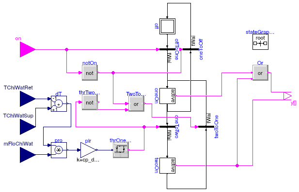
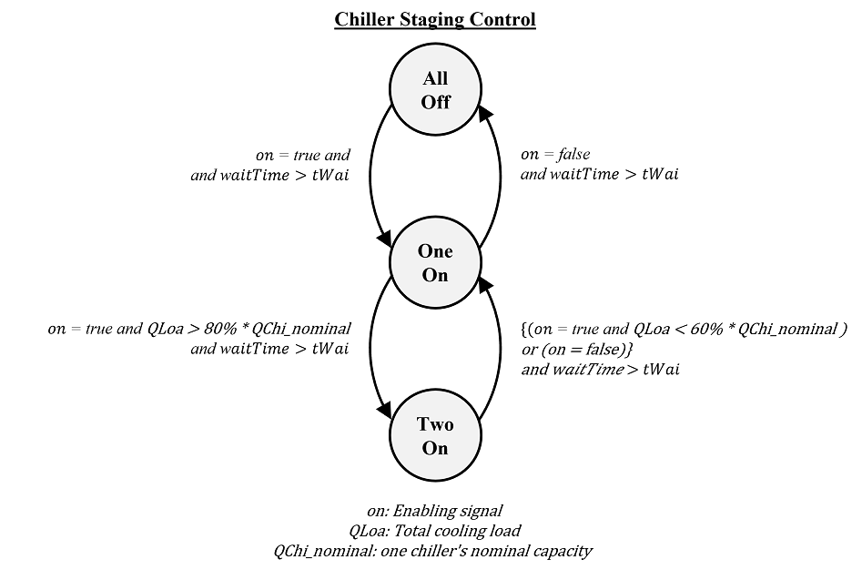
This model implements the staging control logic as follows:


It is assumed that both chillers have the same capacity of QChi_nominal.

Note: This model can be used for plants with two chillers with or without waterside econimizer (WSE). For plants with WSE, extra control logic on top of this model needs to be added.

State graph.

Parameters

TypeNameDefaultDescription
replaceable package MediumBuildings.Media.WaterService side medium
TimetWai Waiting time [s]
PowerQChi_nominal Nominal cooling capacity (negative) [W]
PowerstaUpThr-0.8*QChi_nominalStage up load threshold(from one to two chillers) [W]
PowerstaDowThr-0.6*QChi_nominalStage down load threshold(from two to one chiller) [W]

Connectors

TypeNameDescription
replaceable package MediumService side medium
input BooleanInputonEnabling signal of the plant. True: chiller should be enabled
input RealInputTChiWatRetChilled water return temperature
input RealInputTChiWatSupChilled water supply temperature
input RealInputmFloChiWatChilled water mass flow rate
output BooleanOutputy[2]On/off signal for the chillers - false: off; true: on

Modelica definition

model ChillerStage "Chiller staging controller for plants with two chillers of the same size" replaceable package Medium=Buildings.Media.Water constrainedby Modelica.Media.Interfaces.PartialMedium "Service side medium"; parameter Modelica.SIunits.Time tWai "Waiting time"; parameter Modelica.SIunits.Power QChi_nominal( final max=0) "Nominal cooling capacity (negative)"; parameter Modelica.SIunits.Power staUpThr(final min=0)=-0.8*QChi_nominal "Stage up load threshold(from one to two chillers)"; parameter Modelica.SIunits.Power staDowThr(final min=0)=-0.6*QChi_nominal "Stage down load threshold(from two to one chiller)"; inner Modelica.StateGraph.StateGraphRoot stateGraphRoot "State graph root"; Modelica.Blocks.Interfaces.BooleanInput on "Enabling signal of the plant. True: chiller should be enabled"; Modelica.Blocks.Interfaces.RealInput TChiWatRet "Chilled water return temperature"; Modelica.Blocks.Interfaces.RealInput TChiWatSup "Chilled water supply temperature"; Modelica.Blocks.Interfaces.RealInput mFloChiWat "Chilled water mass flow rate"; Modelica.Blocks.Interfaces.BooleanOutput y[2] "On/off signal for the chillers - false: off; true: on"; Modelica.StateGraph.InitialStep off(nIn=1) "No cooling is demanded"; Modelica.StateGraph.StepWithSignal oneOn( nOut=2, nIn=2) "Status of one chiller on"; Modelica.StateGraph.StepWithSignal twoOn(nOut=2) "Status of two chillers on"; Modelica.StateGraph.TransitionWithSignal offToOne( enableTimer=true, waitTime=tWai) "Condition of transition from off to one chiller on"; Modelica.StateGraph.TransitionWithSignal oneToTwo( enableTimer=true, waitTime=tWai) "Condition of transition from one chiller to two chillers"; Modelica.StateGraph.TransitionWithSignal twoToOne( enableTimer=true, waitTime=tWai) "Condition of transion from two chillers to one chiller"; Modelica.StateGraph.TransitionWithSignal oneToOff( enableTimer=true, waitTime=tWai) "Condition of transition from one chiller to off"; Buildings.Controls.OBC.CDL.Continuous.Hysteresis thrOneToTwo(uLow=-staDowThr/ QChi_nominal, uHigh=-staUpThr/QChi_nominal) "Threshold of turning two chillers on"; Modelica.Blocks.Logical.Not thrTwoToOne "Threshold of turning off the second chiller"; Modelica.Blocks.Math.Add dT( final k1=-1, final k2=+1) "Temperature difference"; Modelica.Blocks.Math.Product pro "Product"; Modelica.Blocks.Math.Gain plr(final k=cp_default/QChi_nominal) "Specific heat multiplier to calculate heat flow rate"; Buildings.Controls.OBC.CDL.Logical.Or Or "On signal for either chiller"; Modelica.Blocks.Logical.Not notOn "on switches to false"; Modelica.Blocks.Logical.Or TwoToOne "Conditions that turn off the second chiller"; protected final parameter Medium.ThermodynamicState sta_default=Medium.setState_pTX( T=Medium.T_default, p=Medium.p_default, X=Medium.X_default) "Medium state at default properties"; final parameter Modelica.SIunits.SpecificHeatCapacity cp_default= Medium.specificHeatCapacityCp( sta_default) "Specific heat capacity of the fluid"; equation connect(off.outPort[1],offToOne.inPort); connect(oneToTwo.outPort,twoOn.inPort[1]); connect(twoToOne.outPort,oneOn.inPort[2]); connect(oneOn.outPort[2],oneToOff.inPort); connect(oneOn.outPort[1],oneToTwo.inPort); connect(oneToTwo.condition,thrOneToTwo.y); connect(dT.y,pro.u1); connect(plr.u, pro.y); connect(plr.y, thrOneToTwo.u); connect(dT.u1,TChiWatRet); connect(TChiWatSup,dT.u2); connect(pro.u2,mFloChiWat); connect(oneToTwo.condition, thrTwoToOne.u); connect(oneOn.active, Or.u1); connect(twoOn.active, Or.u2); connect(Or.y, y[1]); connect(twoOn.active, y[2]); connect(on, notOn.u); connect(twoOn.outPort[1],twoToOne.inPort); connect(offToOne.outPort,oneOn.inPort[1]); connect(oneToOff.outPort,off.inPort[1]); connect(on, offToOne.condition); connect(thrTwoToOne.y, TwoToOne.u2); connect(notOn.y, TwoToOne.u1); connect(TwoToOne.y, twoToOne.condition); connect(notOn.y, oneToOff.condition); end ChillerStage;