Buildings.Experimental.DHC.Loads.Validation.BaseClasses
Package with base classes
Information
This package contains base classes that are used to construct the classes in Buildings.Experimental.DHC.Loads.Validation.
Extends from Modelica.Icons.BasesPackage (Icon for packages containing base classes).
Package Content
| Name | Description |
|---|---|
| Model for connecting an agent to a two-pipe distribution network, using fixed resistance pipe model | |
| Model of a two-pipe distribution network, using fixed resistance pipe model | |
| Model of a sensible only two-pipe fan coil unit for cooling, computing a required chilled water mass flow rate | |
| Model of a two-pipe fan coil unit for heating, computing a required heating water mass flow rate | |
| Model of a two-pipe fan coil unit for heating, with a two-way control valve |
 Buildings.Experimental.DHC.Loads.Validation.BaseClasses.Connection2Pipe
Model for connecting an agent to a two-pipe distribution network, using fixed resistance pipe model
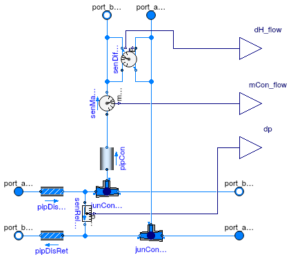
Information
This is a model of a connection with a two-pipe distribution network using as pipe model a fixed hydraulic resistance with no heat loss .
Extends from Networks.BaseClasses.PartialConnection2Pipe (Partial model for connecting an agent to a two-pipe distribution network).
Parameters
| Type | Name | Default | Description |
|---|---|---|---|
| replaceable package Medium | PartialMedium | Medium model | |
| replaceable model Model_pipDis | Fluid.FixedResistances.Press... | ||
| replaceable model Model_pipCon | Fluid.FixedResistances.Lossl... | ||
| Boolean | show_entFlo | false | Set to true to output enthalpy flow rate difference |
| PressureDifference | dpDis_nominal | Pressure drop in distribution line (supply only, not counting return line) [Pa] | |
| Nominal condition | |||
| MassFlowRate | mDis_flow_nominal | Nominal mass flow rate in the distribution line [kg/s] | |
| MassFlowRate | mCon_flow_nominal | Nominal mass flow rate in the connection line [kg/s] | |
| Assumptions | |||
| Boolean | allowFlowReversal | false | = true to allow flow reversal, false restricts to design direction (port_a -> port_b) |
| Dynamics | |||
| Equations | |||
| Dynamics | energyDynamics | Modelica.Fluid.Types.Dynamic... | Type of energy balance: dynamic (3 initialization options) or steady state |
| Nominal condition | |||
| Time | tau | 10 | Time constant at nominal flow for dynamic energy and momentum balance [s] |
Connectors
| Type | Name | Description |
|---|---|---|
| replaceable model Model_pipDis | ||
| replaceable model Model_pipCon | ||
| FluidPort_a | port_aDisSup | Distribution supply inlet port |
| FluidPort_b | port_bDisSup | Distribution supply outlet port |
| FluidPort_a | port_aDisRet | Distribution return inlet port |
| FluidPort_b | port_bDisRet | Distribution return outlet port |
| FluidPort_b | port_bCon | Connection supply port |
| FluidPort_a | port_aCon | Connection return port |
| output RealOutput | mCon_flow | Connection supply mass flow rate [kg/s] |
| output RealOutput | dp | Pressure drop accross the connection (measured) [Pa] |
| output RealOutput | dH_flow | Difference in enthalpy flow rate between connection supply and return [W] |
Modelica definition
 Buildings.Experimental.DHC.Loads.Validation.BaseClasses.Distribution2Pipe
Model of a two-pipe distribution network, using fixed resistance pipe model
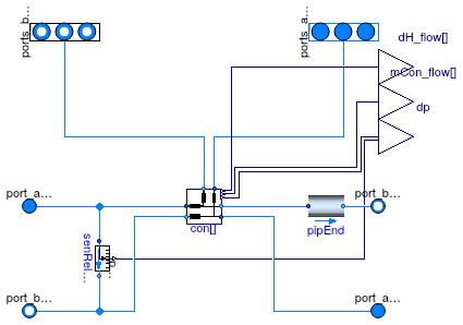
Information
This is a model of a two-pipe distribution network using
- a connection model with fixed hydraulic resistance with no heat loss as a pipe model, and
- a dummy pipe model with no hydraulic resistance and no heat loss for the end of the distribution line (after the last connection).
Extends from Networks.BaseClasses.PartialDistribution2Pipe (Partial model for two-pipe distribution network).
Parameters
| Type | Name | Default | Description |
|---|---|---|---|
| replaceable package Medium | PartialMedium | Medium model | |
| Integer | nCon | Number of connections | |
| replaceable model Model_pipDis | Fluid.FixedResistances.Lossl... | Model for distribution pipe | |
| Integer | iConDpSen | nCon | Index of the connection where the pressure drop is measured |
| Boolean | show_entFlo | false | Set to true to output enthalpy flow rate difference at each connection |
| Nominal condition | |||
| MassFlowRate | mDis_flow_nominal | Nominal mass flow rate in the distribution line before the first connection [kg/s] | |
| MassFlowRate | mCon_flow_nominal[nCon] | Nominal mass flow rate in each connection line [kg/s] | |
| MassFlowRate | mEnd_flow_nominal | mDis_flow_nominal - sum(mCon... | Nominal mass flow rate in the end of the distribution line [kg/s] |
| MassFlowRate | mDisCon_flow_nominal[nCon] | cat(1, {mDis_flow_nominal}, ... | Nominal mass flow rate in the distribution line before each connection [kg/s] |
| PressureDifference | dpDis_nominal[nCon] | Pressure drop in distribution line (supply only, not counting return line) [Pa] | |
| Assumptions | |||
| Boolean | allowFlowReversal | false | = true to allow flow reversal, false restricts to design direction (port_a -> port_b) |
| Dynamics | |||
| Equations | |||
| Dynamics | energyDynamics | Modelica.Fluid.Types.Dynamic... | Type of energy balance: dynamic (3 initialization options) or steady state |
| Nominal condition | |||
| Time | tau | 10 | Time constant at nominal flow for dynamic energy and momentum balance [s] |
Connectors
| Type | Name | Description |
|---|---|---|
| FluidPorts_a | ports_aCon[nCon] | Connection return ports |
| FluidPorts_b | ports_bCon[nCon] | Connection supply ports |
| FluidPort_a | port_aDisSup | Distribution supply inlet port |
| FluidPort_b | port_bDisSup | Distribution supply outlet port |
| replaceable model Model_pipDis | Model for distribution pipe | |
| FluidPort_b | port_bDisRet | Distribution return outlet port |
| FluidPort_a | port_aDisRet | Distribution return inlet port |
| output RealOutput | dp | Pressure difference at given location (measured) [Pa] |
| output RealOutput | dH_flow[nCon] | Difference in enthalpy flow rate between connection supply and return [W] |
| output RealOutput | mCon_flow[nCon] | Connection supply mass flow rate (measured) [kg/s] |
Modelica definition
 Buildings.Experimental.DHC.Loads.Validation.BaseClasses.FanCoil2PipeCooling
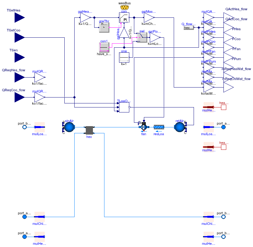
Model of a sensible only two-pipe fan coil unit for cooling,
computing a required chilled water mass flow rate
Information
This is a sensible only simplified model of a two-pipe fan coil unit for cooling. It is intended to be used
- in a case where the room thermal loads are provided as time series: it therefore takes the load as an input, and
- in conjunction with Buildings.Experimental.DHC.Loads.FlowDistribution: it therefore computes the water mass flow rate required to meet the load.
For the sake of simplicity, a sensible only heat exchanger model is considered.
For the sake of computational performance, a PI controller is used instead of an inverse model of the heat exchanger to assess the required water mass flow rate. The controller output signal is mapped linearly to both,
- the water mass flow rate, from zero to its nominal value, and
- the air mass flow rate, from zero to its nominal value.
The controller tracks the load while the impact of an unmet load on the room air temperature is assessed with Buildings.Experimental.DHC.Loads.SimpleRoomODE.
Extends from Buildings.Experimental.DHC.Loads.BaseClasses.PartialTerminalUnit (Partial model for HVAC terminal unit).
Parameters
| Type | Name | Default | Description |
|---|---|---|---|
| replaceable package Medium1 | Water | Medium in the building distribution system | |
| replaceable package Medium2 | Air | Load side medium | |
| Real | k | 1 | Gain of controller |
| Time | Ti | 10 | Time constant of integrator block [s] |
| Scaling | |||
| Real | facMul | 1 | Multiplier factor |
| Real | facMulZon | 1 | Zone multiplier factor |
| Configuration | |||
| Boolean | have_heaWat | false | Set to true if the system uses heating water |
| Boolean | have_chiWat | true | Set to true if the system uses chilled water |
| Boolean | have_chaOve | false | Set to true if the chilled water based heat exchanger operates in change-over |
| Boolean | have_eleHea | false | Set to true if the system has electric heating system |
| Boolean | have_eleCoo | false | Set to true if the system has electric cooling system |
| Boolean | have_heaPor | false | Set to true for heat ports on the load side |
| Boolean | have_fluPor | false | Set to true for fluid ports on the load side |
| Boolean | have_TSen | false | Set to true for measured temperature as an input |
| Boolean | have_QReq_flow | true | Set to true for required heat flow rate as an input |
| Boolean | have_weaBus | false | Set to true to use a weather bus |
| Boolean | have_fan | true | Set to true if fan power is computed |
| Boolean | have_pum | false | Set to true if pump power is computed |
| Boolean | have_speVar | true | Set to true for a variable speed fan (otherwise fan is always on) |
| Nominal condition | |||
| HeatFlowRate | QHea_flow_nominal | 0 | Nominal heating capacity (>=0) [W] |
| HeatFlowRate | QCoo_flow_nominal | 0 | Nominal cooling capacity (<=0) [W] |
| MassFlowRate | mHeaWat_flow_nominal | 0 | Heating water mass flow rate at nominal conditions [kg/s] |
| MassFlowRate | mChiWat_flow_nominal | abs(QCoo_flow_nominal/cpChiW... | Chilled water mass flow rate at nominal conditions [kg/s] |
| MassFlowRate | mLoaHea_flow_nominal | 0 | Load side mass flow rate at nominal conditions in heating mode [kg/s] |
| MassFlowRate | mLoaCoo_flow_nominal | 0 | Load side mass flow rate at nominal conditions in cooling mode [kg/s] |
| Temperature | T_aHeaWat_nominal | 273.15 + 60 | Heating water inlet temperature at nominal conditions [K] |
| Temperature | T_bHeaWat_nominal | T_aHeaWat_nominal - 22.2 | Heating water outlet temperature at nominal conditions [K] |
| Temperature | T_aChiWat_nominal | 273.15 + 7.2 | Chilled water inlet temperature at nominal conditions [K] |
| Temperature | T_bChiWat_nominal | T_aChiWat_nominal + 5.6 | Chilled water outlet temperature at nominal conditions [K] |
| Temperature | T_aLoaHea_nominal | 273.15 + 21.1 | Load side inlet temperature at nominal conditions in heating mode [K] |
| Temperature | T_aLoaCoo_nominal | 273.15 + 26.7 | Load side inlet temperature at nominal conditions in cooling mode [K] |
| PressureDifference | dpLoa_nominal | 250 | Load side pressure drop [Pa] |
| Assumptions | |||
| Boolean | allowFlowReversal | false | Set to true to allow flow reversal in building distribution system |
| Boolean | allowFlowReversalLoa | true | Set to true to allow flow reversal on the load side |
Connectors
| Type | Name | Description |
|---|---|---|
| replaceable package Medium1 | Medium in the building distribution system | |
| replaceable package Medium2 | Load side medium | |
| input RealInput | TSen | Temperature (measured) [K] |
| input RealInput | TSetHea | Heating set point [K] |
| input RealInput | TSetCoo | Cooling set point [K] |
| input RealInput | QReqHea_flow | Required heat flow rate to meet heating set point (>=0) [W] |
| input RealInput | QReqCoo_flow | Required heat flow rate to meet cooling set point (<=0) [W] |
| output RealOutput | QActHea_flow | Heating heat flow rate transferred to the load (>=0) [W] |
| output RealOutput | QActCoo_flow | Cooling heat flow rate transferred to the load (<=0) [W] |
| output RealOutput | PHea | Power drawn by heating system [W] |
| output RealOutput | PCoo | Power drawn by cooling system [W] |
| output RealOutput | PFan | Power drawn by fans motors [W] |
| output RealOutput | PPum | Power drawn by pumps motors [W] |
| output RealOutput | mReqHeaWat_flow | Required heating water flow rate to meet heating set point [kg/s] |
| output RealOutput | mReqChiWat_flow | Required chilled water flow rate to meet cooling set point [kg/s] |
| FluidPort_a | port_aLoa | Fluid stream inlet port on the load side |
| FluidPort_b | port_bLoa | Fluid stream outlet port on the load side |
| HeatPort_b | heaPorCon | Heat port transferring convective heat to the load |
| HeatPort_b | heaPorRad | Heat port transferring radiative heat to the load |
| Bus | weaBus | Weather data bus |
| FluidPort_a | port_aHeaWat | Heating water inlet port |
| FluidPort_a | port_aChiWat | Chilled water inlet port |
| FluidPort_b | port_bHeaWat | Heating water outlet port |
| FluidPort_b | port_bChiWat | Chilled water outlet port |
Modelica definition
Buildings.Experimental.DHC.Loads.Validation.BaseClasses.FanCoil2PipeHeating
Model of a two-pipe fan coil unit for heating,
computing a required heating water mass flow rate
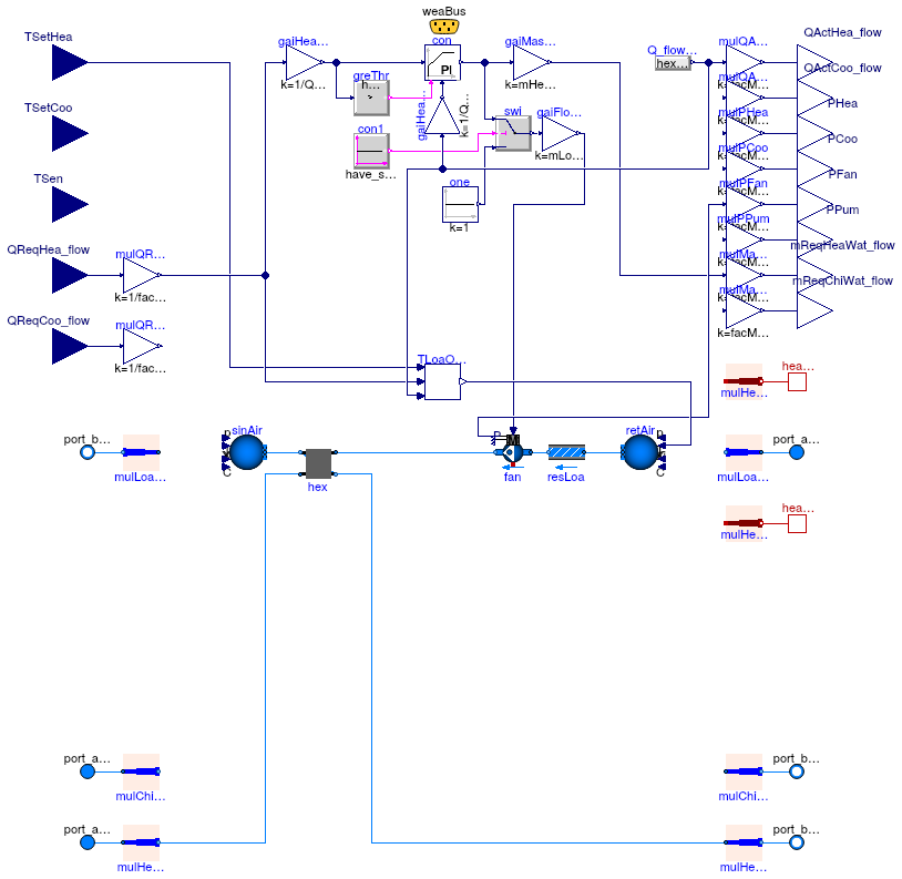
Information
This is a simplified model of a two-pipe fan coil unit for heating. It is intended to be used
- in a case where the room thermal loads are provided as time series: it therefore takes the load as an input, and
- in conjunction with Buildings.Experimental.DHC.Loads.FlowDistribution: it therefore computes the water mass flow rate required to meet the load.
For the sake of computational performance, a PI controller is used instead of an inverse model of the heat exchanger to assess the required water mass flow rate. The controller output signal is mapped linearly to both,
- the water mass flow rate, from zero to its nominal value, and
- the air mass flow rate, from zero to its nominal value.
The controller tracks the load while the impact of an unmet load on the room air temperature is assessed with Buildings.Experimental.DHC.Loads.SimpleRoomODE.
Extends from Buildings.Experimental.DHC.Loads.BaseClasses.PartialTerminalUnit (Partial model for HVAC terminal unit).
Parameters
| Type | Name | Default | Description |
|---|---|---|---|
| replaceable package Medium1 | Water | Medium in the building distribution system | |
| replaceable package Medium2 | Air | Load side medium | |
| Real | k | 1 | Gain of controller |
| Time | Ti | 10 | Time constant of integrator block [s] |
| Scaling | |||
| Real | facMul | 1 | Multiplier factor |
| Real | facMulZon | 1 | Zone multiplier factor |
| Configuration | |||
| Boolean | have_heaWat | true | Set to true if the system uses heating water |
| Boolean | have_chiWat | false | Set to true if the system uses chilled water |
| Boolean | have_chaOve | false | Set to true if the chilled water based heat exchanger operates in change-over |
| Boolean | have_eleHea | false | Set to true if the system has electric heating system |
| Boolean | have_eleCoo | false | Set to true if the system has electric cooling system |
| Boolean | have_heaPor | false | Set to true for heat ports on the load side |
| Boolean | have_fluPor | false | Set to true for fluid ports on the load side |
| Boolean | have_TSen | false | Set to true for measured temperature as an input |
| Boolean | have_QReq_flow | true | Set to true for required heat flow rate as an input |
| Boolean | have_weaBus | false | Set to true to use a weather bus |
| Boolean | have_fan | true | Set to true if fan power is computed |
| Boolean | have_pum | false | Set to true if pump power is computed |
| Boolean | have_speVar | true | Set to true for a variable speed fan (otherwise fan is always on) |
| Nominal condition | |||
| HeatFlowRate | QHea_flow_nominal | 0 | Nominal heating capacity (>=0) [W] |
| HeatFlowRate | QCoo_flow_nominal | 0 | Nominal cooling capacity (<=0) [W] |
| MassFlowRate | mHeaWat_flow_nominal | abs(QHea_flow_nominal/cpHeaW... | Heating water mass flow rate at nominal conditions [kg/s] |
| MassFlowRate | mChiWat_flow_nominal | 0 | Chilled water mass flow rate at nominal conditions [kg/s] |
| MassFlowRate | mLoaHea_flow_nominal | 0 | Load side mass flow rate at nominal conditions in heating mode [kg/s] |
| MassFlowRate | mLoaCoo_flow_nominal | 0 | Load side mass flow rate at nominal conditions in cooling mode [kg/s] |
| Temperature | T_aHeaWat_nominal | 273.15 + 60 | Heating water inlet temperature at nominal conditions [K] |
| Temperature | T_bHeaWat_nominal | T_aHeaWat_nominal - 22.2 | Heating water outlet temperature at nominal conditions [K] |
| Temperature | T_aChiWat_nominal | 273.15 + 7.2 | Chilled water inlet temperature at nominal conditions [K] |
| Temperature | T_bChiWat_nominal | T_aChiWat_nominal + 5.6 | Chilled water outlet temperature at nominal conditions [K] |
| Temperature | T_aLoaHea_nominal | 273.15 + 21.1 | Load side inlet temperature at nominal conditions in heating mode [K] |
| Temperature | T_aLoaCoo_nominal | 273.15 + 26.7 | Load side inlet temperature at nominal conditions in cooling mode [K] |
| PressureDifference | dpLoa_nominal | 250 | Load side pressure drop [Pa] |
| Assumptions | |||
| Boolean | allowFlowReversal | false | Set to true to allow flow reversal in building distribution system |
| Boolean | allowFlowReversalLoa | true | Set to true to allow flow reversal on the load side |
Connectors
| Type | Name | Description |
|---|---|---|
| replaceable package Medium1 | Medium in the building distribution system | |
| replaceable package Medium2 | Load side medium | |
| input RealInput | TSen | Temperature (measured) [K] |
| input RealInput | TSetHea | Heating set point [K] |
| input RealInput | TSetCoo | Cooling set point [K] |
| input RealInput | QReqHea_flow | Required heat flow rate to meet heating set point (>=0) [W] |
| input RealInput | QReqCoo_flow | Required heat flow rate to meet cooling set point (<=0) [W] |
| output RealOutput | QActHea_flow | Heating heat flow rate transferred to the load (>=0) [W] |
| output RealOutput | QActCoo_flow | Cooling heat flow rate transferred to the load (<=0) [W] |
| output RealOutput | PHea | Power drawn by heating system [W] |
| output RealOutput | PCoo | Power drawn by cooling system [W] |
| output RealOutput | PFan | Power drawn by fans motors [W] |
| output RealOutput | PPum | Power drawn by pumps motors [W] |
| output RealOutput | mReqHeaWat_flow | Required heating water flow rate to meet heating set point [kg/s] |
| output RealOutput | mReqChiWat_flow | Required chilled water flow rate to meet cooling set point [kg/s] |
| FluidPort_a | port_aLoa | Fluid stream inlet port on the load side |
| FluidPort_b | port_bLoa | Fluid stream outlet port on the load side |
| HeatPort_b | heaPorCon | Heat port transferring convective heat to the load |
| HeatPort_b | heaPorRad | Heat port transferring radiative heat to the load |
| Bus | weaBus | Weather data bus |
| FluidPort_a | port_aHeaWat | Heating water inlet port |
| FluidPort_a | port_aChiWat | Chilled water inlet port |
| FluidPort_b | port_bHeaWat | Heating water outlet port |
| FluidPort_b | port_bChiWat | Chilled water outlet port |
Modelica definition
Buildings.Experimental.DHC.Loads.Validation.BaseClasses.FanCoil2PipeHeatingValve
Model of a two-pipe fan coil unit for heating, with a two-way control valve
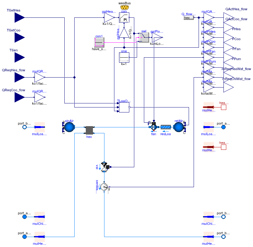
Information
This is a simplified model of a two-pipe fan coil unit for heating. It is intended to be used in a case where the room thermal loads are provided as time series, and hence it takes the load as an input.
A PI controller tracks the load. The controller output signal is mapped linearly to both,
- the opening of a two-way control valve, and
- the air mass flow rate, from zero to its nominal value.
The impact of an unmet load on the room air temperature is assessed with Buildings.Experimental.DHC.Loads.SimpleRoomODE.
Extends from Buildings.Experimental.DHC.Loads.BaseClasses.PartialTerminalUnit (Partial model for HVAC terminal unit).
Parameters
| Type | Name | Default | Description |
|---|---|---|---|
| replaceable package Medium1 | Water | Medium in the building distribution system | |
| replaceable package Medium2 | Air | Load side medium | |
| Boolean | have_speVar | true | Set to true for a variable speed fan (otherwise fan is always on) |
| PressureDifference | dpSou_nominal | 30000 | Nominal pressure drop on source side [Pa] |
| Scaling | |||
| Real | facMul | 1 | Multiplier factor |
| Real | facMulZon | 1 | Zone multiplier factor |
| Configuration | |||
| Boolean | have_heaWat | true | Set to true if the system uses heating water |
| Boolean | have_chiWat | false | Set to true if the system uses chilled water |
| Boolean | have_chaOve | false | Set to true if the chilled water based heat exchanger operates in change-over |
| Boolean | have_eleHea | false | Set to true if the system has electric heating system |
| Boolean | have_eleCoo | false | Set to true if the system has electric cooling system |
| Boolean | have_heaPor | false | Set to true for heat ports on the load side |
| Boolean | have_fluPor | false | Set to true for fluid ports on the load side |
| Boolean | have_TSen | false | Set to true for measured temperature as an input |
| Boolean | have_QReq_flow | true | Set to true for required heat flow rate as an input |
| Boolean | have_weaBus | false | Set to true to use a weather bus |
| Boolean | have_fan | true | Set to true if fan power is computed |
| Boolean | have_pum | false | Set to true if pump power is computed |
| Nominal condition | |||
| HeatFlowRate | QHea_flow_nominal | 0 | Nominal heating capacity (>=0) [W] |
| HeatFlowRate | QCoo_flow_nominal | 0 | Nominal cooling capacity (<=0) [W] |
| MassFlowRate | mHeaWat_flow_nominal | abs(QHea_flow_nominal/cpHeaW... | Heating water mass flow rate at nominal conditions [kg/s] |
| MassFlowRate | mChiWat_flow_nominal | 0 | Chilled water mass flow rate at nominal conditions [kg/s] |
| MassFlowRate | mLoaHea_flow_nominal | 0 | Load side mass flow rate at nominal conditions in heating mode [kg/s] |
| MassFlowRate | mLoaCoo_flow_nominal | 0 | Load side mass flow rate at nominal conditions in cooling mode [kg/s] |
| Temperature | T_aHeaWat_nominal | 273.15 + 60 | Heating water inlet temperature at nominal conditions [K] |
| Temperature | T_bHeaWat_nominal | T_aHeaWat_nominal - 22.2 | Heating water outlet temperature at nominal conditions [K] |
| Temperature | T_aChiWat_nominal | 273.15 + 7.2 | Chilled water inlet temperature at nominal conditions [K] |
| Temperature | T_bChiWat_nominal | T_aChiWat_nominal + 5.6 | Chilled water outlet temperature at nominal conditions [K] |
| Temperature | T_aLoaHea_nominal | 273.15 + 21.1 | Load side inlet temperature at nominal conditions in heating mode [K] |
| Temperature | T_aLoaCoo_nominal | 273.15 + 26.7 | Load side inlet temperature at nominal conditions in cooling mode [K] |
| PressureDifference | dpLoa_nominal | 250 | Load side pressure drop [Pa] |
| Assumptions | |||
| Boolean | allowFlowReversal | false | Set to true to allow flow reversal in building distribution system |
| Boolean | allowFlowReversalLoa | true | Set to true to allow flow reversal on the load side |
Connectors
| Type | Name | Description |
|---|---|---|
| replaceable package Medium1 | Medium in the building distribution system | |
| replaceable package Medium2 | Load side medium | |
| input RealInput | TSen | Temperature (measured) [K] |
| input RealInput | TSetHea | Heating set point [K] |
| input RealInput | TSetCoo | Cooling set point [K] |
| input RealInput | QReqHea_flow | Required heat flow rate to meet heating set point (>=0) [W] |
| input RealInput | QReqCoo_flow | Required heat flow rate to meet cooling set point (<=0) [W] |
| output RealOutput | QActHea_flow | Heating heat flow rate transferred to the load (>=0) [W] |
| output RealOutput | QActCoo_flow | Cooling heat flow rate transferred to the load (<=0) [W] |
| output RealOutput | PHea | Power drawn by heating system [W] |
| output RealOutput | PCoo | Power drawn by cooling system [W] |
| output RealOutput | PFan | Power drawn by fans motors [W] |
| output RealOutput | PPum | Power drawn by pumps motors [W] |
| output RealOutput | mReqHeaWat_flow | Required heating water flow rate to meet heating set point [kg/s] |
| output RealOutput | mReqChiWat_flow | Required chilled water flow rate to meet cooling set point [kg/s] |
| FluidPort_a | port_aLoa | Fluid stream inlet port on the load side |
| FluidPort_b | port_bLoa | Fluid stream outlet port on the load side |
| HeatPort_b | heaPorCon | Heat port transferring convective heat to the load |
| HeatPort_b | heaPorRad | Heat port transferring radiative heat to the load |
| Bus | weaBus | Weather data bus |
| FluidPort_a | port_aHeaWat | Heating water inlet port |
| FluidPort_a | port_aChiWat | Chilled water inlet port |
| FluidPort_b | port_bHeaWat | Heating water outlet port |
| FluidPort_b | port_bChiWat | Chilled water outlet port |