Buildings.Fluid.HeatExchangers
Package with heat exchanger models
Information
This package contains models for heat exchangers with and without humidity condensation.Extends from Modelica.Icons.VariantsPackage (Icon for package containing variants).
Package Content
| Name | Description |
|---|---|
| Heat exchanger with constant effectiveness | |
| Counterflow coil with discretization along the flow paths and without humidity condensation | |
| Coil with discretization along the flow paths and no humidity condensation | |
| Heat exchanger with effectiveness - NTU relation and no moisture condensation | |
| Evaporator or condenser with refrigerant experiencing constant temperature phase change | |
| Heater or cooler with prescribed heat flow rate | |
| Heater with prescribed outlet temperature | |
| Plate heat exchanger with effectiveness - NTU relation and no moisture condensation | |
| Ideal heater, cooler, humidifier or dehumidifier with prescribed outlet conditions | |
| Sensible cooling device with prescribed outlet temperature | |
| Counterflow coil with discretization along the flow paths and humidity condensation | |
| Coil with discretization along the flow paths and humidity condensation | |
| Heat exchanger with effectiveness - NTU relation and with moisture condensation | |
| Package with active beams | |
| Package with cooling tower models | |
| DX(Direct Expansion) cooling coil models | |
| Package with radiant slab models | |
| Package with radiators models for hydronic space heating systems | |
| Collection of models that illustrate model use and test models | |
| Collection of models that validate the heat exchanger models | |
| Package with base classes for Buildings.Fluid.HeatExchangers |
 Buildings.Fluid.HeatExchangers.ConstantEffectiveness
Heat exchanger with constant effectiveness

Information
Model for a heat exchanger with constant effectiveness.
This model transfers heat in the amount of
Q = Qmax ε,
where ε is a constant effectiveness and Qmax is the maximum heat that can be transferred.
For a heat and moisture exchanger, use Buildings.Fluid.MassExchangers.ConstantEffectiveness instead of this model.
Extends from Buildings.Fluid.HeatExchangers.BaseClasses.PartialEffectiveness (Partial model to implement heat exchangers based on effectiveness model).
Parameters
| Type | Name | Default | Description |
|---|---|---|---|
| replaceable package Medium1 | PartialMedium | Medium 1 in the component | |
| replaceable package Medium2 | PartialMedium | Medium 2 in the component | |
| Boolean | sensibleOnly1 | true | Set to true if sensible exchange only for medium 1 |
| Boolean | sensibleOnly2 | true | Set to true if sensible exchange only for medium 2 |
| Efficiency | eps | 0.8 | Heat exchanger effectiveness [1] |
| Nominal condition | |||
| MassFlowRate | m1_flow_nominal | Nominal mass flow rate [kg/s] | |
| MassFlowRate | m2_flow_nominal | Nominal mass flow rate [kg/s] | |
| PressureDifference | dp1_nominal | Pressure difference [Pa] | |
| PressureDifference | dp2_nominal | Pressure difference [Pa] | |
| Custom Parameters | |||
| HeatFlowRate | Q1_flow | eps*QMax_flow | Heat transferred into the medium 1 [W] |
| MassFlowRate | mWat1_flow | 0 | Moisture mass flow rate added to the medium 1 [kg/s] |
| HeatFlowRate | Q2_flow | -Q1_flow | Heat transferred into the medium 2 [W] |
| MassFlowRate | mWat2_flow | 0 | Moisture mass flow rate added to the medium 2 [kg/s] |
| Assumptions | |||
| Boolean | allowFlowReversal1 | true | = false to simplify equations, assuming, but not enforcing, no flow reversal for medium 1 |
| Boolean | allowFlowReversal2 | true | = false to simplify equations, assuming, but not enforcing, no flow reversal for medium 2 |
| Advanced | |||
| MassFlowRate | m1_flow_small | 1E-4*abs(m1_flow_nominal) | Small mass flow rate for regularization of zero flow [kg/s] |
| MassFlowRate | m2_flow_small | 1E-4*abs(m2_flow_nominal) | Small mass flow rate for regularization of zero flow [kg/s] |
| Diagnostics | |||
| Boolean | show_T | false | = true, if actual temperature at port is computed |
| Flow resistance | |||
| Medium 1 | |||
| Boolean | from_dp1 | false | = true, use m_flow = f(dp) else dp = f(m_flow) |
| Boolean | linearizeFlowResistance1 | false | = true, use linear relation between m_flow and dp for any flow rate |
| Real | deltaM1 | 0.1 | Fraction of nominal flow rate where flow transitions to laminar |
| Medium 2 | |||
| Boolean | from_dp2 | false | = true, use m_flow = f(dp) else dp = f(m_flow) |
| Boolean | linearizeFlowResistance2 | false | = true, use linear relation between m_flow and dp for any flow rate |
| Real | deltaM2 | 0.1 | Fraction of nominal flow rate where flow transitions to laminar |
Connectors
| Type | Name | Description |
|---|---|---|
| FluidPort_a | port_a1 | Fluid connector a1 (positive design flow direction is from port_a1 to port_b1) |
| FluidPort_b | port_b1 | Fluid connector b1 (positive design flow direction is from port_a1 to port_b1) |
| FluidPort_a | port_a2 | Fluid connector a2 (positive design flow direction is from port_a2 to port_b2) |
| FluidPort_b | port_b2 | Fluid connector b2 (positive design flow direction is from port_a2 to port_b2) |
Modelica definition
 Buildings.Fluid.HeatExchangers.DryCoilCounterFlow
Counterflow coil with discretization along the flow paths and without humidity condensation
Information
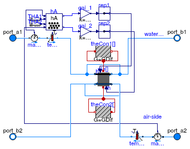
Model of a discretized coil without water vapor condensation.
The coil consists of two flow paths which are, at the design flow direction,
in opposite direction to model a counterflow heat exchanger.
The flow paths are discretized into nEle elements.
Each element is modeled by an instance of
Buildings.Fluid.HeatExchangers.BaseClasses.HexElementSensible.
Each element has a state variable for the metal.
The convective heat transfer coefficients can, for each fluid individually, be computed as a function of the flow rate and/or the temperature, or assigned to a constant. This computation is done using an instance of Buildings.Fluid.HeatExchangers.BaseClasses.HADryCoil.
To model humidity condensation, use the model Buildings.Fluid.HeatExchangers.WetCoilCounterFlow instead of this model, as this model computes only sensible heat transfer.
Implementation
At very small flow rates, which may be caused when the fan is off but there is wind pressure
on the building that entrains outside air through the HVAC system, large temperature differences
could occur if diffusion were neglected.
This model therefore approximates a small diffusion between the elements to have more uniform
medium temperatures if the flow is near zero.
The approximation is done using the heat conductors heaCon1 and heaCon2.
As this is a rough approximation, neighboring elements are connected through these heat conduction
elements, ignoring the actual geometrical configuration.
Also, radiation between the coil surfaces on the air side is not modelled explicitly, but
rather may be considered as approximated by these heat conductors.
Extends from Buildings.Fluid.Interfaces.PartialFourPortInterface (Partial model transporting fluid between two ports without storing mass or energy), Buildings.Fluid.Interfaces.FourPortFlowResistanceParameters (Parameters for flow resistance for models with four ports).
Parameters
| Type | Name | Default | Description |
|---|---|---|---|
| replaceable package Medium1 | PartialMedium | Medium 1 in the component | |
| replaceable package Medium2 | PartialMedium | Medium 2 in the component | |
| Nominal condition | |||
| MassFlowRate | m1_flow_nominal | Nominal mass flow rate [kg/s] | |
| MassFlowRate | m2_flow_nominal | Nominal mass flow rate [kg/s] | |
| PressureDifference | dp1_nominal | Pressure difference [Pa] | |
| PressureDifference | dp2_nominal | Pressure difference [Pa] | |
| ThermalConductance | UA_nominal | Thermal conductance at nominal flow, used to compute heat capacity [W/K] | |
| Real | r_nominal | 2/3 | Ratio between air-side and water-side convective heat transfer coefficient |
| Time | tau1 | 10 | Time constant at nominal flow for medium 1 [s] |
| Time | tau2 | 2 | Time constant at nominal flow for medium 2 [s] |
| Time | tau_m | 5 | Time constant of metal at nominal UA value [s] |
| Geometry | |||
| Integer | nEle | 4 | Number of pipe segments used for discretization |
| Assumptions | |||
| Boolean | allowFlowReversal1 | true | = false to simplify equations, assuming, but not enforcing, no flow reversal for medium 1 |
| Boolean | allowFlowReversal2 | true | = false to simplify equations, assuming, but not enforcing, no flow reversal for medium 2 |
| Advanced | |||
| MassFlowRate | m1_flow_small | 1E-4*abs(m1_flow_nominal) | Small mass flow rate for regularization of zero flow [kg/s] |
| MassFlowRate | m2_flow_small | 1E-4*abs(m2_flow_nominal) | Small mass flow rate for regularization of zero flow [kg/s] |
| Diagnostics | |||
| Boolean | show_T | false | = true, if actual temperature at port is computed |
| Flow resistance | |||
| Medium 1 | |||
| Boolean | computeFlowResistance1 | false | =true, compute flow resistance. Set to false to assume no friction |
| Boolean | from_dp1 | false | = true, use m_flow = f(dp) else dp = f(m_flow) |
| Boolean | linearizeFlowResistance1 | false | = true, use linear relation between m_flow and dp for any flow rate |
| Real | deltaM1 | 0.1 | Fraction of nominal flow rate where flow transitions to laminar |
| Medium 2 | |||
| Boolean | computeFlowResistance2 | false | =true, compute flow resistance. Set to false to assume no friction |
| Boolean | from_dp2 | false | = true, use m_flow = f(dp) else dp = f(m_flow) |
| Boolean | linearizeFlowResistance2 | false | = true, use linear relation between m_flow and dp for any flow rate |
| Real | deltaM2 | 0.1 | Fraction of nominal flow rate where flow transitions to laminar |
| Dynamics | |||
| Equations | |||
| Dynamics | energyDynamics | Modelica.Fluid.Types.Dynamic... | Formulation of energy balance |
| Heat transfer | |||
| Boolean | waterSideFlowDependent | true | Set to false to make water-side hA independent of mass flow rate |
| Boolean | airSideFlowDependent | true | Set to false to make air-side hA independent of mass flow rate |
| Boolean | waterSideTemperatureDependent | false | Set to false to make water-side hA independent of temperature |
| Boolean | airSideTemperatureDependent | false | Set to false to make air-side hA independent of temperature |
| Experimental | |||
| ThermalConductance | GDif | 1E-2*UA_nominal/(nEle - 1) | Thermal conductance to approximate diffusion (which improves model at near-zero flow rates [W/K] |
Connectors
| Type | Name | Description |
|---|---|---|
| FluidPort_a | port_a1 | Fluid connector a1 (positive design flow direction is from port_a1 to port_b1) |
| FluidPort_b | port_b1 | Fluid connector b1 (positive design flow direction is from port_a1 to port_b1) |
| FluidPort_a | port_a2 | Fluid connector a2 (positive design flow direction is from port_a2 to port_b2) |
| FluidPort_b | port_b2 | Fluid connector b2 (positive design flow direction is from port_a2 to port_b2) |
Modelica definition
 Buildings.Fluid.HeatExchangers.DryCoilDiscretized
Coil with discretization along the flow paths and no humidity condensation

Information
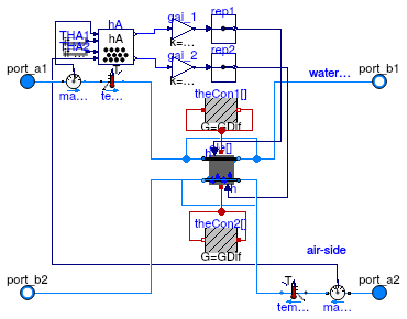
Model of a discretized coil with no water vapor condensation.
The coil consists of nReg registers
that are perpendicular to the air flow path. Each register consists of nPipPar
parallel pipes, and each pipe can be divided into nPipSeg pipe segments along
the pipe length. Thus, the smallest element of the coil consists of a pipe
segment. Each pipe segment is modeled by an instance of
Buildings.Fluid.HeatExchangers.BaseClasses.HexElementSensible.
Each element has a state variable for the metal.
If the parameter energyDynamics is different from
Modelica.Fluid.Types.Dynamics.SteadyState, then
a mixing volume of length dl is added to the duct connection. This can
help reducing the dimension of the nonlinear system of equations.
The convective heat transfer coefficients can, for each fluid individually, be computed as a function of the flow rate and/or the temperature, or assigned to a constant. This computation is done using an instance of Buildings.Fluid.HeatExchangers.BaseClasses.HADryCoil.
In this model, the water (or liquid) flow path
needs to be connected to port_a1 and port_b1, and
the air flow path need to be connected to the other two ports.
To model humidity condensation, use the model Buildings.Fluid.HeatExchangers.WetCoilDiscretized instead of this model, as this model computes only sensible heat transfer.
Implementation
At very small flow rates, which may be caused when the fan is off but there is wind pressure
on the building that entrains outside air through the HVAC system, large temperature differences
could occur if diffusion were neglected.
This model therefore approximates a small diffusion between the elements to have more uniform
medium temperatures if the flow is near zero.
The approximation is done using the heat conductors heaCon1 and heaCon2.
As this is a rough approximation, neighboring elements are connected through these heat conduction
elements, ignoring the actual geometrical configuration.
Also, radiation between the coil surfaces on the air side is not modelled explicitly, but
rather may be considered as approximated by these heat conductors.
Extends from Buildings.Fluid.Interfaces.PartialFourPortInterface (Partial model transporting fluid between two ports without storing mass or energy), Buildings.Fluid.Interfaces.FourPortFlowResistanceParameters (Parameters for flow resistance for models with four ports).
Parameters
| Type | Name | Default | Description |
|---|---|---|---|
| replaceable package Medium1 | PartialMedium | Medium 1 in the component | |
| replaceable package Medium2 | PartialMedium | Medium 2 in the component | |
| Nominal condition | |||
| MassFlowRate | m1_flow_nominal | Nominal mass flow rate [kg/s] | |
| MassFlowRate | m2_flow_nominal | Nominal mass flow rate [kg/s] | |
| PressureDifference | dp1_nominal | Pressure difference [Pa] | |
| PressureDifference | dp2_nominal | Pressure difference [Pa] | |
| ThermalConductance | UA_nominal | Thermal conductance at nominal flow, used to compute heat capacity [W/K] | |
| Time | tau1 | 20 | Time constant at nominal flow for medium 1 [s] |
| Time | tau2 | 10 | Time constant at nominal flow for medium 2 [s] |
| Time | tau_m | 20 | Time constant of metal at nominal UA value [s] |
| Geometry | |||
| Integer | nReg | 2 | Number of registers |
| Integer | nPipPar | 3 | Number of parallel pipes in each register |
| Integer | nPipSeg | 4 | Number of pipe segments per register used for discretization |
| Length | dh1 | 0.025 | Hydraulic diameter for a single pipe [m] |
| Length | dh2 | 1 | Hydraulic diameter for duct [m] |
| Initialization | |||
| MassFlowRate | mStart_flow_a1 | m1_flow_nominal | Guess value for mass flow rate at port_a1 [kg/s] |
| MassFlowRate | mStart_flow_a2 | m2_flow_nominal | Guess value for mass flow rate at port_a2 [kg/s] |
| Assumptions | |||
| Boolean | allowFlowReversal1 | true | = false to simplify equations, assuming, but not enforcing, no flow reversal for medium 1 |
| Boolean | allowFlowReversal2 | true | = false to simplify equations, assuming, but not enforcing, no flow reversal for medium 2 |
| Advanced | |||
| MassFlowRate | m1_flow_small | 1E-4*abs(m1_flow_nominal) | Small mass flow rate for regularization of zero flow [kg/s] |
| MassFlowRate | m2_flow_small | 1E-4*abs(m2_flow_nominal) | Small mass flow rate for regularization of zero flow [kg/s] |
| Boolean | use_dh1 | false | Set to true to specify hydraulic diameter for pipe pressure drop |
| Boolean | use_dh2 | false | Set to true to specify hydraulic diameter for duct pressure drop) |
| Real | ReC_1 | 4000 | Reynolds number where transition to turbulent starts inside pipes |
| Real | ReC_2 | 4000 | Reynolds number where transition to turbulent starts inside ducts |
| Diagnostics | |||
| Boolean | show_T | false | = true, if actual temperature at port is computed |
| Flow resistance | |||
| Medium 1 | |||
| Boolean | computeFlowResistance1 | true | =true, compute flow resistance. Set to false to assume no friction |
| Boolean | from_dp1 | false | = true, use m_flow = f(dp) else dp = f(m_flow) |
| Boolean | linearizeFlowResistance1 | false | = true, use linear relation between m_flow and dp for any flow rate |
| Real | deltaM1 | 0.1 | Fraction of nominal flow rate where flow transitions to laminar |
| Medium 2 | |||
| Boolean | computeFlowResistance2 | true | =true, compute flow resistance. Set to false to assume no friction |
| Boolean | from_dp2 | false | = true, use m_flow = f(dp) else dp = f(m_flow) |
| Boolean | linearizeFlowResistance2 | false | = true, use linear relation between m_flow and dp for any flow rate |
| Real | deltaM2 | 0.1 | Fraction of nominal flow rate where flow transitions to laminar |
| Dynamics | |||
| Equations | |||
| Dynamics | energyDynamics | Modelica.Fluid.Types.Dynamic... | Formulation of energy balance |
| Heat transfer | |||
| Boolean | waterSideFlowDependent | false | Set to false to make water-side hA independent of mass flow rate |
| Boolean | airSideFlowDependent | false | Set to false to make air-side hA independent of mass flow rate |
| Boolean | waterSideTemperatureDependent | false | Set to false to make water-side hA independent of temperature |
Connectors
| Type | Name | Description |
|---|---|---|
| FluidPort_a | port_a1 | Fluid connector a1 (positive design flow direction is from port_a1 to port_b1) |
| FluidPort_b | port_b1 | Fluid connector b1 (positive design flow direction is from port_a1 to port_b1) |
| FluidPort_a | port_a2 | Fluid connector a2 (positive design flow direction is from port_a2 to port_b2) |
| FluidPort_b | port_b2 | Fluid connector b2 (positive design flow direction is from port_a2 to port_b2) |
Modelica definition
 Buildings.Fluid.HeatExchangers.DryCoilEffectivenessNTU
Heat exchanger with effectiveness - NTU relation and no moisture condensation

Information
Model of a coil without humidity condensation. This model transfers heat in the amount of
Q̇ = Q̇max ε
ε = f(NTU, Z, flowRegime),
where Q̇max is the maximum heat that can be transferred, ε is the heat transfer effectiveness, NTU is the Number of Transfer Units, Z is the ratio of minimum to maximum capacity flow rate and flowRegime is the heat exchanger flow regime. such as parallel flow, cross flow or counter flow.
The flow regimes depend on the heat exchanger configuration. All configurations defined in Buildings.Fluid.Types.HeatExchangerConfiguration are supported.
The convective heat transfer coefficients scale proportional to (ṁ/ṁ0)n, where ṁ is the mass flow rate, ṁ0 is the nominal mass flow rate, and n=0.8 on the air-side and n=0.85 on the water side.
For a heat and moisture exchanger, use Buildings.Fluid.MassExchangers.ConstantEffectiveness.
Extends from Buildings.Fluid.HeatExchangers.BaseClasses.PartialEffectivenessNTU (Partial model for heat exchanger with effectiveness - NTU relation and no moisture condensation).
Parameters
| Type | Name | Default | Description |
|---|---|---|---|
| replaceable package Medium1 | PartialMedium | Medium 1 in the component | |
| replaceable package Medium2 | PartialMedium | Medium 2 in the component | |
| HeatExchangerConfiguration | configuration | Heat exchanger configuration | |
| Real | r_nominal | 2/3 | Ratio between air-side and water-side convective heat transfer (hA-value) at nominal condition |
| Nominal condition | |||
| MassFlowRate | m1_flow_nominal | Nominal mass flow rate [kg/s] | |
| MassFlowRate | m2_flow_nominal | Nominal mass flow rate [kg/s] | |
| PressureDifference | dp1_nominal | Pressure difference [Pa] | |
| PressureDifference | dp2_nominal | Pressure difference [Pa] | |
| Nominal thermal performance | |||
| Boolean | use_Q_flow_nominal | true | Set to true to specify Q_flow_nominal and temperatures, or to false to specify effectiveness |
| HeatFlowRate | Q_flow_nominal | Nominal heat flow rate (positive for heat transfer from 1 to 2) [W] | |
| Temperature | T_a1_nominal | Nominal temperature at port a1 [K] | |
| Temperature | T_a2_nominal | Nominal temperature at port a2 [K] | |
| Real | eps_nominal | Nominal heat transfer effectiveness | |
| Custom Parameters | |||
| ThermalConductance | UA | 1/(1/hA.hA_1 + 1/hA.hA_2) | UA value [W/K] |
| Assumptions | |||
| Boolean | allowFlowReversal1 | true | = false to simplify equations, assuming, but not enforcing, no flow reversal for medium 1 |
| Boolean | allowFlowReversal2 | true | = false to simplify equations, assuming, but not enforcing, no flow reversal for medium 2 |
| Advanced | |||
| MassFlowRate | m1_flow_small | 1E-4*abs(m1_flow_nominal) | Small mass flow rate for regularization of zero flow [kg/s] |
| MassFlowRate | m2_flow_small | 1E-4*abs(m2_flow_nominal) | Small mass flow rate for regularization of zero flow [kg/s] |
| Diagnostics | |||
| Boolean | show_T | false | = true, if actual temperature at port is computed |
| Flow resistance | |||
| Medium 1 | |||
| Boolean | from_dp1 | false | = true, use m_flow = f(dp) else dp = f(m_flow) |
| Boolean | linearizeFlowResistance1 | false | = true, use linear relation between m_flow and dp for any flow rate |
| Real | deltaM1 | 0.1 | Fraction of nominal flow rate where flow transitions to laminar |
| Medium 2 | |||
| Boolean | from_dp2 | false | = true, use m_flow = f(dp) else dp = f(m_flow) |
| Boolean | linearizeFlowResistance2 | false | = true, use linear relation between m_flow and dp for any flow rate |
| Real | deltaM2 | 0.1 | Fraction of nominal flow rate where flow transitions to laminar |
Connectors
| Type | Name | Description |
|---|---|---|
| FluidPort_a | port_a1 | Fluid connector a1 (positive design flow direction is from port_a1 to port_b1) |
| FluidPort_b | port_b1 | Fluid connector b1 (positive design flow direction is from port_a1 to port_b1) |
| FluidPort_a | port_a2 | Fluid connector a2 (positive design flow direction is from port_a2 to port_b2) |
| FluidPort_b | port_b2 | Fluid connector b2 (positive design flow direction is from port_a2 to port_b2) |
Modelica definition
 Buildings.Fluid.HeatExchangers.EvaporatorCondenser
Evaporator or condenser with refrigerant experiencing constant temperature phase change
Information
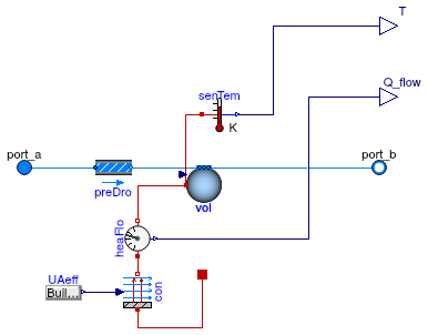
Model for a constant temperature evaporator or condenser based on a ε-NTU heat exchanger model.
The heat exchanger effectiveness is calculated from the number of transfer units (NTU):
ε = 1 - exp(UA ⁄ (ṁ cp))
Optionally, this model can have a flow resistance.
If no flow resistance is requested, set dp_nominal=0.
Limitations
This model does not consider any superheating or supercooling on the refrigerant side. The refrigerant is considered to exchange heat at a constant temperature throughout the heat exchanger.
Extends from Buildings.Fluid.Interfaces.TwoPortHeatMassExchanger (Partial model transporting one fluid stream with storing mass or energy).
Parameters
| Type | Name | Default | Description |
|---|---|---|---|
| replaceable package Medium | PartialMedium | Medium in the component | |
| ThermalConductance | UA | Thermal conductance of heat exchanger [W/K] | |
| Nominal condition | |||
| MassFlowRate | m_flow_nominal | Nominal mass flow rate [kg/s] | |
| PressureDifference | dp_nominal | Pressure difference [Pa] | |
| Assumptions | |||
| Boolean | allowFlowReversal | true | = false to simplify equations, assuming, but not enforcing, no flow reversal |
| Advanced | |||
| MassFlowRate | m_flow_small | 1E-4*abs(m_flow_nominal) | Small mass flow rate for regularization of zero flow [kg/s] |
| ThermalConductance | UA_small | UA/10 | Small thermal conductance for regularisation of heat transfer [W/K] |
| Diagnostics | |||
| Boolean | show_T | false | = true, if actual temperature at port is computed |
| Flow resistance | |||
| Boolean | from_dp | false | = true, use m_flow = f(dp) else dp = f(m_flow) |
| Boolean | linearizeFlowResistance | false | = true, use linear relation between m_flow and dp for any flow rate |
| Real | deltaM | 0.1 | Fraction of nominal flow rate where flow transitions to laminar |
| Dynamics | |||
| Nominal condition | |||
| Time | tau | 30 | Time constant at nominal flow (if energyDynamics <> SteadyState) [s] |
| Equations | |||
| Dynamics | energyDynamics | Modelica.Fluid.Types.Dynamic... | Type of energy balance: dynamic (3 initialization options) or steady state |
| Dynamics | massDynamics | energyDynamics | Type of mass balance: dynamic (3 initialization options) or steady state |
| Initialization | |||
| AbsolutePressure | p_start | Medium.p_default | Start value of pressure [Pa] |
| Temperature | T_start | Medium.T_default | Start value of temperature [K] |
| MassFraction | X_start[Medium.nX] | Medium.X_default | Start value of mass fractions m_i/m [kg/kg] |
| ExtraProperty | C_start[Medium.nC] | fill(0, Medium.nC) | Start value of trace substances |
Connectors
| Type | Name | Description |
|---|---|---|
| FluidPort_a | port_a | Fluid connector a (positive design flow direction is from port_a to port_b) |
| FluidPort_b | port_b | Fluid connector b (positive design flow direction is from port_a to port_b) |
| output RealOutput | Q_flow | Heat added to the fluid [W] |
| output RealOutput | T | Medium temperature [K] |
| HeatPort_a | port_ref | Temperature and heat flow from the refrigerant |
Modelica definition
 Buildings.Fluid.HeatExchangers.HeaterCooler_u
Heater or cooler with prescribed heat flow rate
Information
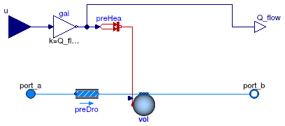
Model for an ideal heater or cooler with prescribed heat flow rate to the medium.
This model adds heat in the amount of Q_flow = u Q_flow_nominal to the medium.
The input signal u and the nominal heat flow rate Q_flow_nominal
can be positive or negative. A positive value of Q_flow means
heating, and negative means cooling.
The outlet conditions at port_a are not affected by this model,
other than for a possible pressure difference due to flow friction.
Optionally, this model can have a flow resistance.
Set dp_nominal = 0 to disable the flow friction calculation.
For a model that uses as an input the fluid temperature leaving at
port_b, use
Buildings.Fluid.HeatExchangers.PrescribedOutlet
Limitations
This model does not affect the humidity of the air. Therefore, if used to cool air below the dew point temperature, the water mass fraction will not change.
Validation
The model has been validated against the analytical solution in the example Buildings.Fluid.HeatExchangers.Validation.HeaterCooler_u.
Extends from Buildings.Fluid.Interfaces.TwoPortHeatMassExchanger (Partial model transporting one fluid stream with storing mass or energy).
Parameters
| Type | Name | Default | Description |
|---|---|---|---|
| replaceable package Medium | PartialMedium | Medium in the component | |
| HeatFlowRate | Q_flow_nominal | Heat flow rate at u=1, positive for heating [W] | |
| Nominal condition | |||
| MassFlowRate | m_flow_nominal | Nominal mass flow rate [kg/s] | |
| PressureDifference | dp_nominal | Pressure difference [Pa] | |
| Assumptions | |||
| Boolean | allowFlowReversal | true | = false to simplify equations, assuming, but not enforcing, no flow reversal |
| Advanced | |||
| MassFlowRate | m_flow_small | 1E-4*abs(m_flow_nominal) | Small mass flow rate for regularization of zero flow [kg/s] |
| Diagnostics | |||
| Boolean | show_T | false | = true, if actual temperature at port is computed |
| Flow resistance | |||
| Boolean | from_dp | false | = true, use m_flow = f(dp) else dp = f(m_flow) |
| Boolean | linearizeFlowResistance | false | = true, use linear relation between m_flow and dp for any flow rate |
| Real | deltaM | 0.1 | Fraction of nominal flow rate where flow transitions to laminar |
| Dynamics | |||
| Nominal condition | |||
| Time | tau | 30 | Time constant at nominal flow (if energyDynamics <> SteadyState) [s] |
| Equations | |||
| Dynamics | energyDynamics | Modelica.Fluid.Types.Dynamic... | Type of energy balance: dynamic (3 initialization options) or steady state |
| Dynamics | massDynamics | energyDynamics | Type of mass balance: dynamic (3 initialization options) or steady state |
| Initialization | |||
| AbsolutePressure | p_start | Medium.p_default | Start value of pressure [Pa] |
| Temperature | T_start | Medium.T_default | Start value of temperature [K] |
| MassFraction | X_start[Medium.nX] | Medium.X_default | Start value of mass fractions m_i/m [kg/kg] |
| ExtraProperty | C_start[Medium.nC] | fill(0, Medium.nC) | Start value of trace substances |
Connectors
| Type | Name | Description |
|---|---|---|
| FluidPort_a | port_a | Fluid connector a (positive design flow direction is from port_a to port_b) |
| FluidPort_b | port_b | Fluid connector b (positive design flow direction is from port_a to port_b) |
| input RealInput | u | Control input [1] |
| output RealOutput | Q_flow | Heat added to the fluid [W] |
Modelica definition
 Buildings.Fluid.HeatExchangers.Heater_T
Heater with prescribed outlet temperature
Information
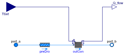
Model for an ideal heater that controls its outlet temperature to a prescribed outlet temperature.
This model forces the outlet temperature at port_b to be
no lower than the temperature of the input signal
TSet, subject to optional limits on the
capacity.
By default, the model has unlimited heating capacity.
The output signal Q_flow is the heat added
to the medium if the mass flow rate is from port_a to port_b.
If the flow is reversed, then Q_flow=0.
The outlet conditions at port_a are not affected by this model,
other than for a possible pressure difference due to flow friction.
If the parameter energyDynamics is different from
Modelica.Fluid.Types.Dynamics.SteadyState,
the component models the dynamic response using a first order differential equation.
The time constant of the component is equal to the parameter tau.
This time constant is adjusted based on the mass flow rate using
τeff = τ |ṁ| ⁄ ṁnom
where τeff is the effective time constant for the given mass flow rate ṁ and τ is the time constant at the nominal mass flow rate ṁnom. This type of dynamics is equal to the dynamics that a completely mixed control volume would have.
Optionally, this model can have a flow resistance.
Set dp_nominal = 0 to disable the flow friction calculation.
For a similar model that is a sensible cooling device, use Buildings.Fluid.HeatExchangers.SensibleCooler_T. For a model that uses a control signal u ∈ [0, 1] and multiplies this with the nominal heating or cooling power, use Buildings.Fluid.HeatExchangers.HeaterCooler_u
Limitations
If the flow is from port_b to port_a,
then the enthalpy of the medium is not affected by this model.
Validation
The model has been validated against the analytical solution in the examples Buildings.Fluid.HeatExchangers.Validation.PrescribedOutlet and Buildings.Fluid.HeatExchangers.Validation.PrescribedOutlet_dynamic.
Extends from Buildings.Fluid.HeatExchangers.BaseClasses.PartialPrescribedOutlet (Ideal heater, cooler, humidifier or dehumidifier with prescribed outlet conditions).
Parameters
| Type | Name | Default | Description |
|---|---|---|---|
| replaceable package Medium | PartialMedium | Medium in the component | |
| HeatFlowRate | QMax_flow | Modelica.Constants.inf | Maximum heat flow rate for heating (positive) [W] |
| Nominal condition | |||
| MassFlowRate | m_flow_nominal | Nominal mass flow rate [kg/s] | |
| PressureDifference | dp_nominal | Pressure difference [Pa] | |
| Assumptions | |||
| Boolean | allowFlowReversal | true | = false to simplify equations, assuming, but not enforcing, no flow reversal |
| Advanced | |||
| MassFlowRate | m_flow_small | 1E-4*abs(m_flow_nominal) | Small mass flow rate for regularization of zero flow [kg/s] |
| Diagnostics | |||
| Boolean | show_T | false | = true, if actual temperature at port is computed |
| Flow resistance | |||
| Boolean | from_dp | false | = true, use m_flow = f(dp) else dp = f(m_flow) |
| Boolean | linearizeFlowResistance | false | = true, use linear relation between m_flow and dp for any flow rate |
| Real | deltaM | 0.1 | Fraction of nominal flow rate where flow transitions to laminar |
| Dynamics | |||
| Time | tau | 10 | Time constant at nominal flow rate (used if energyDynamics or massDynamics not equal Modelica.Fluid.Types.Dynamics.SteadyState) [s] |
| Equations | |||
| Dynamics | energyDynamics | Modelica.Fluid.Types.Dynamic... | Type of energy balance: dynamic (3 initialization options) or steady state |
| Initialization | |||
| Temperature | T_start | Medium.T_default | Start value of temperature [K] |
Connectors
| Type | Name | Description |
|---|---|---|
| FluidPort_a | port_a | Fluid connector a (positive design flow direction is from port_a to port_b) |
| FluidPort_b | port_b | Fluid connector b (positive design flow direction is from port_a to port_b) |
| input RealInput | TSet | Set point temperature of the fluid that leaves port_b [K] |
| output RealOutput | Q_flow | Heat flow rate added to the fluid (if flow is from port_a to port_b) [W] |
Modelica definition
 Buildings.Fluid.HeatExchangers.PlateHeatExchangerEffectivenessNTU
Plate heat exchanger with effectiveness - NTU relation and no moisture condensation

Information
Model of a plate heat exchanger without humidity condensation. This model transfers heat in the amount of
Q̇ = Q̇max ε
ε = f(NTU, Z, flowRegime),
where Q̇max is the maximum heat that can be transferred, ε is the heat transfer effectiveness, NTU is the Number of Transfer Units, Z is the ratio of minimum to maximum capacity flow rate and flowRegime is the heat exchanger flow regime. such as parallel flow, cross flow or counter flow.
The flow regimes depend on the heat exchanger configuration. All configurations defined in Buildings.Fluid.Types.HeatExchangerConfiguration are supported.
The convective heat transfer coefficients scale proportional to (ṁ/ṁ0)n, where ṁ is the mass flow rate, ṁ0 is the nominal mass flow rate, and n=0.8 for both streams.
For a plate exchanger, use Buildings.Fluid.HeatExchangers.PlateHeatExchangerEffectivenessNTU.
For a heat and moisture exchanger, use Buildings.Fluid.MassExchangers.ConstantEffectiveness.
Extends from Buildings.Fluid.HeatExchangers.BaseClasses.PartialEffectivenessNTU (Partial model for heat exchanger with effectiveness - NTU relation and no moisture condensation).
Parameters
| Type | Name | Default | Description |
|---|---|---|---|
| replaceable package Medium1 | PartialMedium | Medium 1 in the component | |
| replaceable package Medium2 | PartialMedium | Medium 2 in the component | |
| HeatExchangerConfiguration | configuration | Heat exchanger configuration | |
| Nominal condition | |||
| MassFlowRate | m1_flow_nominal | Nominal mass flow rate [kg/s] | |
| MassFlowRate | m2_flow_nominal | Nominal mass flow rate [kg/s] | |
| PressureDifference | dp1_nominal | Pressure difference [Pa] | |
| PressureDifference | dp2_nominal | Pressure difference [Pa] | |
| Nominal thermal performance | |||
| Boolean | use_Q_flow_nominal | true | Set to true to specify Q_flow_nominal and temperatures, or to false to specify effectiveness |
| HeatFlowRate | Q_flow_nominal | Nominal heat flow rate (positive for heat transfer from 1 to 2) [W] | |
| Temperature | T_a1_nominal | Nominal temperature at port a1 [K] | |
| Temperature | T_a2_nominal | Nominal temperature at port a2 [K] | |
| Real | eps_nominal | Nominal heat transfer effectiveness | |
| Custom Parameters | |||
| ThermalConductance | UA | 1/(1/hA1 + 1/hA2) | UA value [W/K] |
| Assumptions | |||
| Boolean | allowFlowReversal1 | true | = false to simplify equations, assuming, but not enforcing, no flow reversal for medium 1 |
| Boolean | allowFlowReversal2 | true | = false to simplify equations, assuming, but not enforcing, no flow reversal for medium 2 |
| Advanced | |||
| MassFlowRate | m1_flow_small | 1E-4*abs(m1_flow_nominal) | Small mass flow rate for regularization of zero flow [kg/s] |
| MassFlowRate | m2_flow_small | 1E-4*abs(m2_flow_nominal) | Small mass flow rate for regularization of zero flow [kg/s] |
| Diagnostics | |||
| Boolean | show_T | false | = true, if actual temperature at port is computed |
| Flow resistance | |||
| Medium 1 | |||
| Boolean | from_dp1 | false | = true, use m_flow = f(dp) else dp = f(m_flow) |
| Boolean | linearizeFlowResistance1 | false | = true, use linear relation between m_flow and dp for any flow rate |
| Real | deltaM1 | 0.1 | Fraction of nominal flow rate where flow transitions to laminar |
| Medium 2 | |||
| Boolean | from_dp2 | false | = true, use m_flow = f(dp) else dp = f(m_flow) |
| Boolean | linearizeFlowResistance2 | false | = true, use linear relation between m_flow and dp for any flow rate |
| Real | deltaM2 | 0.1 | Fraction of nominal flow rate where flow transitions to laminar |
Connectors
| Type | Name | Description |
|---|---|---|
| FluidPort_a | port_a1 | Fluid connector a1 (positive design flow direction is from port_a1 to port_b1) |
| FluidPort_b | port_b1 | Fluid connector b1 (positive design flow direction is from port_a1 to port_b1) |
| FluidPort_a | port_a2 | Fluid connector a2 (positive design flow direction is from port_a2 to port_b2) |
| FluidPort_b | port_b2 | Fluid connector b2 (positive design flow direction is from port_a2 to port_b2) |
Modelica definition
 Buildings.Fluid.HeatExchangers.PrescribedOutlet
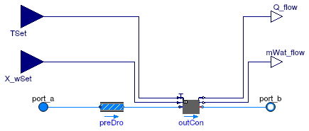
Ideal heater, cooler, humidifier or dehumidifier with prescribed outlet conditions
Information
Model that allows specifying the temperature and mass fraction of the fluid
that leaves the model from port_b.
This model forces the outlet temperature at port_b to be equal to the temperature
of the input signal TSet, subject to optional limits on the
heating or cooling capacity QMax_flow ≥ 0 and QMin_flow ≤ 0.
Similarly than for the temperature,
this model also forces the outlet water mass fraction at port_b to be
no lower than the
input signal X_wSet, subject to optional limits on the
maximum water vapor mass flow rate that is added, as
described by the parameter mWatMax_flow.
By default, the model has unlimited capacity, but control of temperature
and humidity can be subject to capacity limits, or be disabled.
The output signal Q_flow is the heat added (for heating) or subtracted (for cooling)
to the medium if the flow rate is from port_a to port_b.
If the flow is reversed, then Q_flow=0.
The outlet conditions at port_a are not affected by this model.
If the parameter energyDynamics is not equal to
Modelica.Fluid.Types.Dynamics.SteadyState,
the component models the dynamic response using a first order differential equation.
The time constant of the component is equal to the parameter tau.
This time constant is adjusted based on the mass flow rate using
τeff = τ |ṁ| ⁄ ṁnom
where τeff is the effective time constant for the given mass flow rate ṁ and τ is the time constant at the nominal mass flow rate ṁnom. This type of dynamics is equal to the dynamics that a completely mixed control volume would have.
Optionally, this model can have a flow resistance.
If no flow resistance is requested, set dp_nominal=0.
For a model that uses a control signal u ∈ [0, 1] and multiplies this with the nominal heating or cooling power, use Buildings.Fluid.HeatExchangers.HeaterCooler_u
Limitations
This model only adds or removes heat or water vapor for the flow from
port_a to port_b.
The enthalpy of the reverse flow is not affected by this model.
If this model is used to cool air below the dew point temperature, the water mass fraction will not change.
Note that for use_TSet = false, the enthalpy of the leaving fluid
will not be changed, even if moisture is added. The enthalpy added (or removed)
by the change in humidity is neglected. To properly account for change in enthalpy
due to humidification, use instead
Buildings.Fluid.Humidifiers.SprayAirWasher_X.
Validation
The model has been validated against the analytical solution in the examples Buildings.Fluid.HeatExchangers.Validation.PrescribedOutlet and Buildings.Fluid.HeatExchangers.Validation.PrescribedOutlet_dynamic.
Extends from Buildings.Fluid.HeatExchangers.BaseClasses.PartialPrescribedOutlet (Ideal heater, cooler, humidifier or dehumidifier with prescribed outlet conditions).
Parameters
| Type | Name | Default | Description |
|---|---|---|---|
| replaceable package Medium | PartialMedium | Medium in the component | |
| HeatFlowRate | QMax_flow | Modelica.Constants.inf | Maximum heat flow rate for heating (positive) [W] |
| HeatFlowRate | QMin_flow | -Modelica.Constants.inf | Maximum heat flow rate for cooling (negative) [W] |
| MassFlowRate | mWatMax_flow | Modelica.Constants.inf | Maximum water mass flow rate addition (positive) [kg/s] |
| MassFlowRate | mWatMin_flow | -Modelica.Constants.inf | Maximum water mass flow rate removal (negative) [kg/s] |
| Boolean | use_TSet | true | Set to false to disable temperature set point |
| Boolean | use_X_wSet | true | Set to false to disable water vapor set point |
| Nominal condition | |||
| MassFlowRate | m_flow_nominal | Nominal mass flow rate [kg/s] | |
| PressureDifference | dp_nominal | Pressure difference [Pa] | |
| Assumptions | |||
| Boolean | allowFlowReversal | true | = false to simplify equations, assuming, but not enforcing, no flow reversal |
| Advanced | |||
| MassFlowRate | m_flow_small | 1E-4*abs(m_flow_nominal) | Small mass flow rate for regularization of zero flow [kg/s] |
| Diagnostics | |||
| Boolean | show_T | false | = true, if actual temperature at port is computed |
| Flow resistance | |||
| Boolean | from_dp | false | = true, use m_flow = f(dp) else dp = f(m_flow) |
| Boolean | linearizeFlowResistance | false | = true, use linear relation between m_flow and dp for any flow rate |
| Real | deltaM | 0.1 | Fraction of nominal flow rate where flow transitions to laminar |
| Dynamics | |||
| Time | tau | 10 | Time constant at nominal flow rate (used if energyDynamics or massDynamics not equal Modelica.Fluid.Types.Dynamics.SteadyState) [s] |
| Equations | |||
| Dynamics | energyDynamics | Modelica.Fluid.Types.Dynamic... | Type of energy balance: dynamic (3 initialization options) or steady state |
| Dynamics | massDynamics | energyDynamics | Type of mass balance: dynamic (3 initialization options) or steady state |
| Initialization | |||
| Temperature | T_start | Medium.T_default | Start value of temperature [K] |
| MassFraction | X_start[Medium.nX] | Medium.X_default | Start value of mass fractions m_i/m [1] |
Connectors
| Type | Name | Description |
|---|---|---|
| FluidPort_a | port_a | Fluid connector a (positive design flow direction is from port_a to port_b) |
| FluidPort_b | port_b | Fluid connector b (positive design flow direction is from port_a to port_b) |
| input RealInput | TSet | Set point temperature of the fluid that leaves port_b [K] |
| input RealInput | X_wSet | Set point for water vapor mass fraction of the fluid that leaves port_b [1] |
| output RealOutput | Q_flow | Heat flow rate added to the fluid (if flow is from port_a to port_b) [W] |
| output RealOutput | mWat_flow | Water vapor mass flow rate added to the fluid (if flow is from port_a to port_b) [kg/s] |
Modelica definition
 Buildings.Fluid.HeatExchangers.SensibleCooler_T
Sensible cooling device with prescribed outlet temperature

Information
Model for an ideal sensible-only cooler that controls its outlet temperature to a prescribed outlet temperature.
This model forces the outlet temperature at port_b to be
no higher than the temperature of the input signal
TSet, subject to optional limits on the
capacity.
By default, the model has unlimited cooling capacity.
The output signal Q_flow ≤ 0 is the heat added
to the medium if the mass flow rate is from port_a to port_b.
If the flow is reversed, then Q_flow=0.
The outlet conditions at port_a are not affected by this model,
other than for a possible pressure difference due to flow friction.
If the parameter energyDynamics is different from
Modelica.Fluid.Types.Dynamics.SteadyState,
the component models the dynamic response using a first order differential equation.
The time constant of the component is equal to the parameter tau.
This time constant is adjusted based on the mass flow rate using
τeff = τ |ṁ| ⁄ ṁnom
where τeff is the effective time constant for the given mass flow rate ṁ and τ is the time constant at the nominal mass flow rate ṁnom. This type of dynamics is equal to the dynamics that a completely mixed control volume would have.
Optionally, this model can have a flow resistance.
Set dp_nominal = 0 to disable the flow friction calculation.
For a similar model that is a heater, use Buildings.Fluid.HeatExchangers.Heater_T. For a model that uses a control signal u ∈ [0, 1] and multiplies this with the nominal heating or cooling power, use Buildings.Fluid.HeatExchangers.HeaterCooler_u.
Limitations
If the flow is from port_b to port_a,
then the enthalpy of the medium is not affected by this model.
This model does not affect the humidity of the air. Therefore, if used to cool air below the dew point temperature, the water mass fraction will not change.
Validation
The model has been validated against the analytical solution in the examples Buildings.Fluid.HeatExchangers.Validation.PrescribedOutlet and Buildings.Fluid.HeatExchangers.Validation.PrescribedOutlet_dynamic.
Extends from Buildings.Fluid.HeatExchangers.BaseClasses.PartialPrescribedOutlet (Ideal heater, cooler, humidifier or dehumidifier with prescribed outlet conditions).
Parameters
| Type | Name | Default | Description |
|---|---|---|---|
| replaceable package Medium | PartialMedium | Medium in the component | |
| HeatFlowRate | QMin_flow | -Modelica.Constants.inf | Maximum heat flow rate for cooling (negative) [W] |
| Nominal condition | |||
| MassFlowRate | m_flow_nominal | Nominal mass flow rate [kg/s] | |
| PressureDifference | dp_nominal | Pressure difference [Pa] | |
| Assumptions | |||
| Boolean | allowFlowReversal | true | = false to simplify equations, assuming, but not enforcing, no flow reversal |
| Advanced | |||
| MassFlowRate | m_flow_small | 1E-4*abs(m_flow_nominal) | Small mass flow rate for regularization of zero flow [kg/s] |
| Diagnostics | |||
| Boolean | show_T | false | = true, if actual temperature at port is computed |
| Flow resistance | |||
| Boolean | from_dp | false | = true, use m_flow = f(dp) else dp = f(m_flow) |
| Boolean | linearizeFlowResistance | false | = true, use linear relation between m_flow and dp for any flow rate |
| Real | deltaM | 0.1 | Fraction of nominal flow rate where flow transitions to laminar |
| Dynamics | |||
| Time | tau | 10 | Time constant at nominal flow rate (used if energyDynamics or massDynamics not equal Modelica.Fluid.Types.Dynamics.SteadyState) [s] |
| Equations | |||
| Dynamics | energyDynamics | Modelica.Fluid.Types.Dynamic... | Type of energy balance: dynamic (3 initialization options) or steady state |
| Initialization | |||
| Temperature | T_start | Medium.T_default | Start value of temperature [K] |
Connectors
| Type | Name | Description |
|---|---|---|
| FluidPort_a | port_a | Fluid connector a (positive design flow direction is from port_a to port_b) |
| FluidPort_b | port_b | Fluid connector b (positive design flow direction is from port_a to port_b) |
| input RealInput | TSet | Set point temperature of the fluid that leaves port_b [K] |
| output RealOutput | Q_flow | Heat flow rate added to the fluid (if flow is from port_a to port_b) [W] |
Modelica definition
 Buildings.Fluid.HeatExchangers.WetCoilCounterFlow
Counterflow coil with discretization along the flow paths and humidity condensation
Information
Model of a discretized coil with water vapor condensation.
The coil consists of two flow paths which are, at the design flow direction,
in opposite direction to model a counterflow heat exchanger.
The flow paths are discretized into nEle elements.
Each element is modeled by an instance of
Buildings.Fluid.HeatExchangers.BaseClasses.HexElementLatent.
Each element has a state variable for the metal.
The convective heat transfer coefficients can, for each fluid individually, be computed as a function of the flow rate and/or the temperature, or assigned to a constant. This computation is done using an instance of Buildings.Fluid.HeatExchangers.BaseClasses.HADryCoil.
In this model, the water (or liquid) flow path
needs to be connected to port_a1 and port_b1, and
the air flow path needs to be connected to the other two ports.
The mass transfer from the fluid 2 to the metal is computed using a similarity law between heat and mass transfer, as implemented by the model Buildings.Fluid.HeatExchangers.BaseClasses.MassExchange.
This model can only be used with medium models that
implement the function enthalpyOfLiquid and that contain
an integer variable Water whose value is the element number where
the water vapor is stored in the species concentration vector. Examples for
such media are
Buildings.Media.Air and
Modelica.Media.Air.MoistAir.
To model this coil for conditions without humidity condensation, use the model Buildings.Fluid.HeatExchangers.DryCoilCounterFlow instead of this model.
Extends from Buildings.Fluid.HeatExchangers.DryCoilCounterFlow (Counterflow coil with discretization along the flow paths and without humidity condensation).
Parameters
| Type | Name | Default | Description |
|---|---|---|---|
| replaceable package Medium1 | PartialMedium | Medium 1 in the component | |
| replaceable package Medium2 | PartialMedium | Medium 2 in the component | |
| Nominal condition | |||
| MassFlowRate | m1_flow_nominal | Nominal mass flow rate [kg/s] | |
| MassFlowRate | m2_flow_nominal | Nominal mass flow rate [kg/s] | |
| PressureDifference | dp1_nominal | Pressure difference [Pa] | |
| PressureDifference | dp2_nominal | Pressure difference [Pa] | |
| ThermalConductance | UA_nominal | Thermal conductance at nominal flow, used to compute heat capacity [W/K] | |
| Real | r_nominal | 2/3 | Ratio between air-side and water-side convective heat transfer coefficient |
| Time | tau1 | 10 | Time constant at nominal flow for medium 1 [s] |
| Time | tau2 | 2 | Time constant at nominal flow for medium 2 [s] |
| Time | tau_m | 5 | Time constant of metal at nominal UA value [s] |
| Geometry | |||
| Integer | nEle | 4 | Number of pipe segments used for discretization |
| Assumptions | |||
| Boolean | allowFlowReversal1 | true | = false to simplify equations, assuming, but not enforcing, no flow reversal for medium 1 |
| Boolean | allowFlowReversal2 | true | = false to simplify equations, assuming, but not enforcing, no flow reversal for medium 2 |
| Advanced | |||
| MassFlowRate | m1_flow_small | 1E-4*abs(m1_flow_nominal) | Small mass flow rate for regularization of zero flow [kg/s] |
| MassFlowRate | m2_flow_small | 1E-4*abs(m2_flow_nominal) | Small mass flow rate for regularization of zero flow [kg/s] |
| Diagnostics | |||
| Boolean | show_T | false | = true, if actual temperature at port is computed |
| Flow resistance | |||
| Medium 1 | |||
| Boolean | from_dp1 | false | = true, use m_flow = f(dp) else dp = f(m_flow) |
| Boolean | linearizeFlowResistance1 | false | = true, use linear relation between m_flow and dp for any flow rate |
| Real | deltaM1 | 0.1 | Fraction of nominal flow rate where flow transitions to laminar |
| Medium 2 | |||
| Boolean | from_dp2 | false | = true, use m_flow = f(dp) else dp = f(m_flow) |
| Boolean | linearizeFlowResistance2 | false | = true, use linear relation between m_flow and dp for any flow rate |
| Real | deltaM2 | 0.1 | Fraction of nominal flow rate where flow transitions to laminar |
| Dynamics | |||
| Equations | |||
| Dynamics | energyDynamics | Modelica.Fluid.Types.Dynamic... | Formulation of energy balance |
| Heat transfer | |||
| Boolean | waterSideFlowDependent | true | Set to false to make water-side hA independent of mass flow rate |
| Boolean | airSideFlowDependent | true | Set to false to make air-side hA independent of mass flow rate |
| Boolean | waterSideTemperatureDependent | false | Set to false to make water-side hA independent of temperature |
| Boolean | airSideTemperatureDependent | false | Set to false to make air-side hA independent of temperature |
| Experimental | |||
| ThermalConductance | GDif | 1E-2*UA_nominal/(nEle - 1) | Thermal conductance to approximate diffusion (which improves model at near-zero flow rates [W/K] |
Connectors
| Type | Name | Description |
|---|---|---|
| replaceable package Medium2 | Medium 2 in the component | |
| FluidPort_a | port_a1 | Fluid connector a1 (positive design flow direction is from port_a1 to port_b1) |
| FluidPort_b | port_b1 | Fluid connector b1 (positive design flow direction is from port_a1 to port_b1) |
| FluidPort_a | port_a2 | Fluid connector a2 (positive design flow direction is from port_a2 to port_b2) |
| FluidPort_b | port_b2 | Fluid connector b2 (positive design flow direction is from port_a2 to port_b2) |
Modelica definition
 Buildings.Fluid.HeatExchangers.WetCoilDiscretized
Coil with discretization along the flow paths and humidity condensation
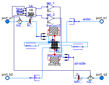
Information
Model of a discretized coil with humidity condensation. This model is identical to Buildings.Fluid.HeatExchangers.DryCoilDiscretized but in addition, the mass transfer from fluid 2 to the metal is computed. The mass transfer is computed using a similarity law between heat and mass transfer, as implemented by the model Buildings.Fluid.HeatExchangers.BaseClasses.MassExchange. See this model for details.
This model can only be used with medium models that
implement the function enthalpyOfLiquid and that contain
an integer variable Water whose value is the element number where
the water vapor is stored in the species concentration vector. Examples for
such media are
Buildings.Media.Air and
Modelica.Media.Air.MoistAir.
Extends from DryCoilDiscretized (Coil with discretization along the flow paths and no humidity condensation).
Parameters
| Type | Name | Default | Description |
|---|---|---|---|
| replaceable package Medium1 | PartialMedium | Medium 1 in the component | |
| replaceable package Medium2 | PartialMedium | Medium 2 in the component | |
| Nominal condition | |||
| MassFlowRate | m1_flow_nominal | Nominal mass flow rate [kg/s] | |
| MassFlowRate | m2_flow_nominal | Nominal mass flow rate [kg/s] | |
| PressureDifference | dp1_nominal | Pressure difference [Pa] | |
| PressureDifference | dp2_nominal | Pressure difference [Pa] | |
| ThermalConductance | UA_nominal | Thermal conductance at nominal flow, used to compute heat capacity [W/K] | |
| Time | tau1 | 20 | Time constant at nominal flow for medium 1 [s] |
| Time | tau2 | 10 | Time constant at nominal flow for medium 2 [s] |
| Time | tau_m | 20 | Time constant of metal at nominal UA value [s] |
| Geometry | |||
| Integer | nReg | 2 | Number of registers |
| Integer | nPipPar | 3 | Number of parallel pipes in each register |
| Integer | nPipSeg | 4 | Number of pipe segments per register used for discretization |
| Length | dh1 | 0.025 | Hydraulic diameter for a single pipe [m] |
| Length | dh2 | 1 | Hydraulic diameter for duct [m] |
| Initialization | |||
| MassFlowRate | mStart_flow_a1 | m1_flow_nominal | Guess value for mass flow rate at port_a1 [kg/s] |
| MassFlowRate | mStart_flow_a2 | m2_flow_nominal | Guess value for mass flow rate at port_a2 [kg/s] |
| Assumptions | |||
| Boolean | allowFlowReversal1 | true | = false to simplify equations, assuming, but not enforcing, no flow reversal for medium 1 |
| Boolean | allowFlowReversal2 | true | = false to simplify equations, assuming, but not enforcing, no flow reversal for medium 2 |
| Advanced | |||
| MassFlowRate | m1_flow_small | 1E-4*abs(m1_flow_nominal) | Small mass flow rate for regularization of zero flow [kg/s] |
| MassFlowRate | m2_flow_small | 1E-4*abs(m2_flow_nominal) | Small mass flow rate for regularization of zero flow [kg/s] |
| Boolean | use_dh1 | false | Set to true to specify hydraulic diameter for pipe pressure drop |
| Boolean | use_dh2 | false | Set to true to specify hydraulic diameter for duct pressure drop) |
| Real | ReC_1 | 4000 | Reynolds number where transition to turbulent starts inside pipes |
| Real | ReC_2 | 4000 | Reynolds number where transition to turbulent starts inside ducts |
| Diagnostics | |||
| Boolean | show_T | false | = true, if actual temperature at port is computed |
| Flow resistance | |||
| Medium 1 | |||
| Boolean | from_dp1 | false | = true, use m_flow = f(dp) else dp = f(m_flow) |
| Boolean | linearizeFlowResistance1 | false | = true, use linear relation between m_flow and dp for any flow rate |
| Real | deltaM1 | 0.1 | Fraction of nominal flow rate where flow transitions to laminar |
| Medium 2 | |||
| Boolean | from_dp2 | false | = true, use m_flow = f(dp) else dp = f(m_flow) |
| Boolean | linearizeFlowResistance2 | false | = true, use linear relation between m_flow and dp for any flow rate |
| Real | deltaM2 | 0.1 | Fraction of nominal flow rate where flow transitions to laminar |
| Dynamics | |||
| Equations | |||
| Dynamics | energyDynamics | Modelica.Fluid.Types.Dynamic... | Formulation of energy balance |
| Heat transfer | |||
| Boolean | waterSideFlowDependent | false | Set to false to make water-side hA independent of mass flow rate |
| Boolean | airSideFlowDependent | false | Set to false to make air-side hA independent of mass flow rate |
| Boolean | waterSideTemperatureDependent | false | Set to false to make water-side hA independent of temperature |
Connectors
| Type | Name | Description |
|---|---|---|
| replaceable package Medium2 | Medium 2 in the component | |
| FluidPort_a | port_a1 | Fluid connector a1 (positive design flow direction is from port_a1 to port_b1) |
| FluidPort_b | port_b1 | Fluid connector b1 (positive design flow direction is from port_a1 to port_b1) |
| FluidPort_a | port_a2 | Fluid connector a2 (positive design flow direction is from port_a2 to port_b2) |
| FluidPort_b | port_b2 | Fluid connector b2 (positive design flow direction is from port_a2 to port_b2) |
Modelica definition
 Buildings.Fluid.HeatExchangers.WetCoilEffectivenessNTU
Heat exchanger with effectiveness - NTU relation and with moisture condensation
Information
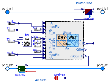
This model describes a cooling coil applicable for fully-dry, partially-wet, and fully-wet regimes. The model is developed for counter flow heat exchangers but is also applicable for the cross-flow configuration, although in the latter case it is recommended to have more than four tube rows (Elmahdy and Mitalas, 1977 and Braun, 1988). The model can also be used for a heat exchanger which acts as both heating coil (for some period of time) and cooling coil (for the others). However, it is not recommended to use this model for heating coil only or for cooling coil with no water condensation because for these situations, Buildings.Fluid.HeatExchangers.DryCoilEffectivenessNTU computes faster.
Main equations
The coil model consists of two-equation sets, one for the fully-dry mode and the other for the fully-wet mode. For the fully-dry mode, the ε-NTU approach (Elmahdy and Mitalas, 1977) is used. For the fully-wet mode, equations from Braun (1988) and Mitchell and Braun (2012a and b), which are essentially the extension of the ε-NTU approach to simultaneous sensible and latent heat transfer, are utilized. The equation sets are switched depending on the switching criteria described below that determines the right mode based on a coil surface temperature and dew-point temperature for the air at the inlet of the coil. The transition regime between the two modes, which represents the partially-wet and partially-dry coil, is approximated by employing a fuzzy modeling approach, so-called Takagi-Sugeno fuzzy modeling (Takagi and Sugeno, 1985), which provides a continuously differentiable model that can cover all fully-dry, partially-wet, and fully-wet regimes.
The switching rules are:
- R1: If the coil surface temperature at the air inlet is lower than the dew-point temperature of air at inlet, then the cooling coil surface is fully-wet.
- R2: If the coil surface temperature at the air outlet is higher than the dew-point temperature of air at inlet, then the cooling coil surface is fully-dry.
- R3: If any of the conditions in R1 or R2 is not satisfied, then the cooling coil surface is partially wet.
For more detailed descriptions of the fully-wet coil model and the fuzzy modeling approach, see Buildings.Fluid.HeatExchangers.BaseClasses.WetCoilWetRegime. and Buildings.Fluid.HeatExchangers.BaseClasses.WetCoilDryWetRegime.
Assumptions and limitations
This model contains the following assumptions and limitations:
Medium 2 must be air due to the use of various psychrometric functions.
When parameterizing this model with rated conditions (with the parameter
use_UA_nominal set to false), those should
correspond to a fully-dry or a fully-wet coil regime, because
the model uncertainty yielded by partially-wet rated conditions
has not been assessed yet.
The model uses steady-state physics. That is, no dynamics associated with water and coil materials are considered.
The Lewis number, which relates the mass transfer coefficient to the heat transfer coefficient, is assumed to be 1.
The model is not suitable for a cross-flow heat exchanger of which the number of passes is less than four.
Validation
Validation results can be found in Buildings.Fluid.HeatExchangers.Validation.WetCoilEffectivenessNTU.
References
Braun, James E. 1988. "Methodologies for the Design and Control of Central Cooling Plants". PhD Thesis. University of Wisconsin - Madison. Available online.
Mitchell, John W., and James E. Braun. 2012a. Principles of heating, ventilation, and air conditioning in buildings. Hoboken, N.J.: Wiley.
Mitchell, John W., and James E. Braun. 2012b. "Supplementary Material Chapter 2: Heat Exchangers for Cooling Applications". Excerpt from Principles of heating, ventilation, and air conditioning in buildings. Hoboken, N.J.: Wiley. Available online.
Elmahdy, A.H. and Mitalas, G.P. 1977. "A Simple Model for Cooling and Dehumidifying Coils for Use In Calculating Energy Requirements for Buildings". ASHRAE Transactions. Vol.83. Part 2. pp. 103-117.
Takagi, T. and Sugeno, M., 1985. Fuzzy identification of systems and its applications to modeling and control. IEEE transactions on systems, man, and cybernetics, (1), pp.116-132.
Extends from Buildings.Fluid.Interfaces.PartialFourPortInterface (Partial model transporting fluid between two ports without storing mass or energy), Buildings.Fluid.Interfaces.FourPortFlowResistanceParameters (Parameters for flow resistance for models with four ports).
Parameters
| Type | Name | Default | Description |
|---|---|---|---|
| replaceable package Medium1 | PartialMedium | Medium 1 in the component | |
| replaceable package Medium2 | PartialMedium | Medium 2 in the component | |
| HeatExchangerConfiguration | configuration | con.CounterFlow | Heat exchanger configuration |
| Real | r_nominal | 2/3 | Ratio between air-side and water-side convective heat transfer coefficient |
| Nominal condition | |||
| MassFlowRate | m1_flow_nominal | Nominal mass flow rate [kg/s] | |
| MassFlowRate | m2_flow_nominal | Nominal mass flow rate [kg/s] | |
| PressureDifference | dp1_nominal | Pressure difference [Pa] | |
| PressureDifference | dp2_nominal | Pressure difference [Pa] | |
| Nominal thermal performance | |||
| Boolean | use_Q_flow_nominal | false | Set to true to specify Q_flow_nominal and inlet conditions, or to false to specify UA_nominal |
| HeatFlowRate | Q_flow_nominal | Nominal heat flow rate (positive for heat transfer from 1 to 2) [W] | |
| Temperature | T_a1_nominal | Water inlet temperature at a rated condition [K] | |
| Temperature | T_a2_nominal | Air inlet temperature at a rated condition [K] | |
| MassFraction | w_a2_nominal | Humidity ratio of inlet air at a rated condition (in kg/kg dry air) [1] | |
| ThermalConductance | UA_nominal | Thermal conductance at nominal flow, used to compute heat capacity [W/K] | |
| Assumptions | |||
| Boolean | allowFlowReversal1 | true | = false to simplify equations, assuming, but not enforcing, no flow reversal for medium 1 |
| Boolean | allowFlowReversal2 | true | = false to simplify equations, assuming, but not enforcing, no flow reversal for medium 2 |
| Advanced | |||
| MassFlowRate | m1_flow_small | 1E-4*abs(m1_flow_nominal) | Small mass flow rate for regularization of zero flow [kg/s] |
| MassFlowRate | m2_flow_small | 1E-4*abs(m2_flow_nominal) | Small mass flow rate for regularization of zero flow [kg/s] |
| Diagnostics | |||
| Boolean | show_T | false | = true, if actual temperature at port is computed |
| Flow resistance | |||
| Medium 1 | |||
| Boolean | computeFlowResistance1 | true | =true, compute flow resistance. Set to false to assume no friction |
| Boolean | from_dp1 | false | = true, use m_flow = f(dp) else dp = f(m_flow) |
| Boolean | linearizeFlowResistance1 | false | = true, use linear relation between m_flow and dp for any flow rate |
| Real | deltaM1 | 0.1 | Fraction of nominal flow rate where flow transitions to laminar |
| Medium 2 | |||
| Boolean | computeFlowResistance2 | true | =true, compute flow resistance. Set to false to assume no friction |
| Boolean | from_dp2 | false | = true, use m_flow = f(dp) else dp = f(m_flow) |
| Boolean | linearizeFlowResistance2 | false | = true, use linear relation between m_flow and dp for any flow rate |
| Real | deltaM2 | 0.1 | Fraction of nominal flow rate where flow transitions to laminar |
| Dynamics | |||
| Equations | |||
| Dynamics | energyDynamics | Modelica.Fluid.Types.Dynamic... | Type of energy balance: dynamic (3 initialization options) or steady state |
| Dynamics | massDynamics | energyDynamics | Type of mass balance: dynamic (3 initialization options) or steady state |
Connectors
| Type | Name | Description |
|---|---|---|
| replaceable package Medium2 | Medium 2 in the component | |
| FluidPort_a | port_a1 | Fluid connector a1 (positive design flow direction is from port_a1 to port_b1) |
| FluidPort_b | port_b1 | Fluid connector b1 (positive design flow direction is from port_a1 to port_b1) |
| FluidPort_a | port_a2 | Fluid connector a2 (positive design flow direction is from port_a2 to port_b2) |
| FluidPort_b | port_b2 | Fluid connector b2 (positive design flow direction is from port_a2 to port_b2) |
Modelica definition
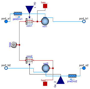
 Buildings.Fluid.HeatExchangers.DryCoilCounterFlow.HexElement
Model for a heat exchanger element
Parameters
| Type | Name | Default | Description |
|---|---|---|---|
| replaceable package Medium1 | PartialMedium | Medium 1 in the component | |
| replaceable package Medium2 | PartialMedium | Medium 2 in the component | |
| HeatCapacity | C | 2*UA_nominal*tau_m | Heat capacity of metal (= cp*m) [J/K] |
| Nominal condition | |||
| MassFlowRate | m1_flow_nominal | Nominal mass flow rate [kg/s] | |
| MassFlowRate | m2_flow_nominal | Nominal mass flow rate [kg/s] | |
| PressureDifference | dp1_nominal | Pressure difference [Pa] | |
| PressureDifference | dp2_nominal | Pressure difference [Pa] | |
| ThermalConductance | UA_nominal | Thermal conductance at nominal flow, used to compute time constant [W/K] | |
| Time | tau_m | 60 | Time constant of metal at nominal UA value [s] |
| Assumptions | |||
| Boolean | allowFlowReversal1 | true | = false to simplify equations, assuming, but not enforcing, no flow reversal for medium 1 |
| Boolean | allowFlowReversal2 | true | = false to simplify equations, assuming, but not enforcing, no flow reversal for medium 2 |
| Advanced | |||
| MassFlowRate | m1_flow_small | 1E-4*abs(m1_flow_nominal) | Small mass flow rate for regularization of zero flow [kg/s] |
| MassFlowRate | m2_flow_small | 1E-4*abs(m2_flow_nominal) | Small mass flow rate for regularization of zero flow [kg/s] |
| Boolean | initialize_p1 | not Medium1.singleState | Set to true to initialize the pressure of volume 1 |
| Boolean | initialize_p2 | not Medium2.singleState | Set to true to initialize the pressure of volume 2 |
| Diagnostics | |||
| Boolean | show_T | false | = true, if actual temperature at port is computed |
| Flow resistance | |||
| Medium 1 | |||
| Boolean | from_dp1 | false | = true, use m_flow = f(dp) else dp = f(m_flow) |
| Boolean | linearizeFlowResistance1 | false | = true, use linear relation between m_flow and dp for any flow rate |
| Real | deltaM1 | 0.1 | Fraction of nominal flow rate where flow transitions to laminar |
| Medium 2 | |||
| Boolean | from_dp2 | false | = true, use m_flow = f(dp) else dp = f(m_flow) |
| Boolean | linearizeFlowResistance2 | false | = true, use linear relation between m_flow and dp for any flow rate |
| Real | deltaM2 | 0.1 | Fraction of nominal flow rate where flow transitions to laminar |
| Dynamics | |||
| Nominal condition | |||
| Time | tau1 | 30 | Time constant at nominal flow [s] |
| Time | tau2 | 30 | Time constant at nominal flow [s] |
| Equations | |||
| Dynamics | energyDynamics | Modelica.Fluid.Types.Dynamic... | Type of energy balance: dynamic (3 initialization options) or steady state |
| Dynamics | massDynamics | energyDynamics | Type of mass balance: dynamic (3 initialization options) or steady state |
| Initialization | |||
| Medium 1 | |||
| AbsolutePressure | p1_start | Medium1.p_default | Start value of pressure [Pa] |
| Temperature | T1_start | Medium1.T_default | Start value of temperature [K] |
| MassFraction | X1_start[Medium1.nX] | Medium1.X_default | Start value of mass fractions m_i/m [kg/kg] |
| ExtraProperty | C1_start[Medium1.nC] | fill(0, Medium1.nC) | Start value of trace substances |
| ExtraProperty | C1_nominal[Medium1.nC] | fill(1E-2, Medium1.nC) | Nominal value of trace substances. (Set to typical order of magnitude.) |
| Medium 2 | |||
| AbsolutePressure | p2_start | Medium2.p_default | Start value of pressure [Pa] |
| Temperature | T2_start | Medium2.T_default | Start value of temperature [K] |
| MassFraction | X2_start[Medium2.nX] | Medium2.X_default | Start value of mass fractions m_i/m [kg/kg] |
| ExtraProperty | C2_start[Medium2.nC] | fill(0, Medium2.nC) | Start value of trace substances |
| ExtraProperty | C2_nominal[Medium2.nC] | fill(1E-2, Medium2.nC) | Nominal value of trace substances. (Set to typical order of magnitude.) |
Connectors
| Type | Name | Description |
|---|---|---|
| FluidPort_a | port_a1 | Fluid connector a1 (positive design flow direction is from port_a1 to port_b1) |
| FluidPort_b | port_b1 | Fluid connector b1 (positive design flow direction is from port_a1 to port_b1) |
| FluidPort_a | port_a2 | Fluid connector a2 (positive design flow direction is from port_a2 to port_b2) |
| FluidPort_b | port_b2 | Fluid connector b2 (positive design flow direction is from port_a2 to port_b2) |
| input RealInput | Gc_1 | Signal representing the convective thermal conductance medium 1 in [W/K] |
| input RealInput | Gc_2 | Signal representing the convective thermal conductance medium 2 in [W/K] |
| HeatPort_a | heaPor1 | Heat port for heat exchange with the control volume 1 |
| HeatPort_a | heaPor2 | Heat port for heat exchange with the control volume 2 |