Buildings.Airflow.Multizone.BaseClasses
Package with base classes for Buildings.Airflow.Multizone
Information
This package contains base classes that are used to construct the models in Buildings.Airflow.Multizone.
Extends from Modelica.Icons.BasesPackage (Icon for packages containing base classes).
Package Content
| Name | Description |
|---|---|
| Partial door model for bi-directional flow | |
| Door model using discretization along height coordinate | |
| Interface that defines parameters for error control | |
| Flow resistance that uses the power law | |
| Flow resistance that uses the power law | |
| Flow resistance that uses the power law | |
| Flow across zonal boundaries of a room | |
| Power law used in orifice equations | |
| Power law used in orifice equations when m is constant | |
| Wind pressure coefficient for low-rise buildings | |
| Collection of models that illustrate model use and test models |
 Buildings.Airflow.Multizone.BaseClasses.Door
Partial door model for bi-directional flow

Information
This is a partial model for the bi-directional air flow through a door.
Extends from Buildings.Fluid.Interfaces.PartialFourPortInterface (Partial model transporting fluid between two ports without storing mass or energy).
Parameters
| Type | Name | Default | Description |
|---|---|---|---|
| replaceable package Medium1 | PartialMedium | Medium 1 in the component | |
| replaceable package Medium2 | PartialMedium | Medium 2 in the component | |
| replaceable package Medium | Modelica.Media.Interfaces.Pa... | Medium in the component | |
| Nominal condition | |||
| MassFlowRate | m1_flow_nominal | 10/3600*1.2 | Nominal mass flow rate [kg/s] |
| MassFlowRate | m2_flow_nominal | m1_flow_nominal | Nominal mass flow rate [kg/s] |
| Geometry | |||
| Length | wOpe | 0.9 | Width of opening [m] |
| Length | hOpe | 2.1 | Height of opening [m] |
| Assumptions | |||
| Boolean | allowFlowReversal1 | true | = false to simplify equations, assuming, but not enforcing, no flow reversal for medium 1 |
| Boolean | allowFlowReversal2 | true | = false to simplify equations, assuming, but not enforcing, no flow reversal for medium 2 |
| Advanced | |||
| MassFlowRate | m1_flow_small | 1E-4*abs(m1_flow_nominal) | Small mass flow rate for regularization of zero flow [kg/s] |
| MassFlowRate | m2_flow_small | 1E-4*abs(m2_flow_nominal) | Small mass flow rate for regularization of zero flow [kg/s] |
| PressureDifference | dp_turbulent | 0.01 | Pressure difference where laminar and turbulent flow relation coincide [Pa] |
| Diagnostics | |||
| Boolean | show_T | false | = true, if actual temperature at port is computed |
Connectors
| Type | Name | Description |
|---|---|---|
| replaceable package Medium1 | Medium 1 in the component | |
| replaceable package Medium2 | Medium 2 in the component | |
| FluidPort_a | port_a1 | Fluid connector a1 (positive design flow direction is from port_a1 to port_b1) |
| FluidPort_b | port_b1 | Fluid connector b1 (positive design flow direction is from port_a1 to port_b1) |
| FluidPort_a | port_a2 | Fluid connector a2 (positive design flow direction is from port_a2 to port_b2) |
| FluidPort_b | port_b2 | Fluid connector b2 (positive design flow direction is from port_a2 to port_b2) |
| replaceable package Medium | Medium in the component | |
Modelica definition
 Buildings.Airflow.Multizone.BaseClasses.DoorDiscretized
Door model using discretization along height coordinate
Information
This is a partial model for the bi-directional air flow through a door.
To compute the bi-directional flow, the door is discretize along the height coordinate, and uses an orifice equation to compute the flow for each compartment.
The compartment area dA is a variable, which allows
using the model for a door that can be open or closed.
Extends from Buildings.Airflow.Multizone.BaseClasses.TwoWayFlowElementBuoyancy (Flow resistance that uses the power law).
Parameters
| Type | Name | Default | Description |
|---|---|---|---|
| replaceable package Medium | PartialMedium | Medium in the component | |
| Velocity | vZer | 0.001 | Minimum velocity to prevent zero flow. Recommended: 0.001 [m/s] |
| Integer | nCom | 10 | Number of compartments for the discretization |
| PressureDifference | dp_turbulent | 0.01 | Pressure difference where laminar and turbulent flow relation coincide. Recommended: 0.01 [Pa] |
| Geometry | |||
| Length | wOpe | 0.9 | Width of opening [m] |
| Length | hOpe | 2.1 | Height of opening [m] |
| Length | hA | 2.7/2 | Height of reference pressure zone A [m] |
| Length | hB | 2.7/2 | Height of reference pressure zone B [m] |
| Advanced | |||
| Diagnostics | |||
| Boolean | show_T | false | = true, if actual temperature at port is computed |
| Boolean | forceErrorControlOnFlow | true | Flag to force error control on m_flow. Set to true if interested in flow rate |
Connectors
| Type | Name | Description |
|---|---|---|
| FluidPort_a | port_a1 | Fluid connector a1 (positive design flow direction is from port_a1 to port_b1) |
| FluidPort_b | port_b1 | Fluid connector b1 (positive design flow direction is from port_a1 to port_b1) |
| FluidPort_a | port_a2 | Fluid connector a2 (positive design flow direction is from port_a2 to port_b2) |
| FluidPort_b | port_b2 | Fluid connector b2 (positive design flow direction is from port_a2 to port_b2) |
Modelica definition
Buildings.Airflow.Multizone.BaseClasses.ErrorControl
Interface that defines parameters for error control
Information
This is an interface that defines parameters used for error control.
Dymola does error control on state variables, such as temperature, pressure and
species concentration.
Flow variables such as m_flow are typically not checked during the error control.
This can give large errors in flow variables, as long as the error on the volume's state variables
that are coupled to the flow variables is small.
Obtaining accurate flow variables can be achieved by imposing an error control
on the exchanged mass, which can be defined as
dm/dt = m_flow.
By setting forceErrorControlOnFlow = true, such an equation is imposed
by models that extend this class.
Parameters
| Type | Name | Default | Description |
|---|---|---|---|
| Advanced | |||
| Boolean | forceErrorControlOnFlow | true | Flag to force error control on m_flow. Set to true if interested in flow rate |
Modelica definition
 Buildings.Airflow.Multizone.BaseClasses.PowerLawResistance
Flow resistance that uses the power law

Information
This model describes the mass flow rate and pressure difference relation of an orifice in the form
V_flow = k * dp^m,
where k is a variable and
m a parameter.
For turbulent flow, set m=1/2 and
for laminar flow, set m=1.
The model is used as a base for the interzonal air flow models.
Extends from Buildings.Fluid.Interfaces.PartialTwoPortInterface (Partial model transporting fluid between two ports without storing mass or energy), Buildings.Airflow.Multizone.BaseClasses.ErrorControl (Interface that defines parameters for error control).
Parameters
| Type | Name | Default | Description |
|---|---|---|---|
| replaceable package Medium | PartialMedium | Medium in the component | |
| Real | m | Flow exponent, m=0.5 for turbulent, m=1 for laminar | |
| Nominal condition | |||
| MassFlowRate | m_flow_nominal | rho_default*k*dp_turbulent | Nominal mass flow rate [kg/s] |
| Assumptions | |||
| Boolean | allowFlowReversal | true | = false to simplify equations, assuming, but not enforcing, no flow reversal |
| Advanced | |||
| MassFlowRate | m_flow_small | 1E-4*abs(m_flow_nominal) | Small mass flow rate for regularization of zero flow [kg/s] |
| Boolean | forceErrorControlOnFlow | true | Flag to force error control on m_flow. Set to true if interested in flow rate |
| Boolean | useDefaultProperties | true | Set to false to use density and viscosity based on actual medium state, rather than using default values |
| PressureDifference | dp_turbulent | 0.1 | Pressure difference where laminar and turbulent flow relation coincide. Recommended = 0.1 [Pa] |
| Diagnostics | |||
| Boolean | show_T | false | = true, if actual temperature at port is computed |
Connectors
| Type | Name | Description |
|---|---|---|
| FluidPort_a | port_a | Fluid connector a (positive design flow direction is from port_a to port_b) |
| FluidPort_b | port_b | Fluid connector b (positive design flow direction is from port_a to port_b) |
Modelica definition
 Buildings.Airflow.Multizone.BaseClasses.TwoWayFlowElement
Flow resistance that uses the power law

Information
This is a partial model for models that describe the bi-directional air flow through large openings.
Models that extend this model need to compute
mAB_flow and mBA_flow,
or alternatively VAB_flow and VBA_flow,
and the face area area.
The face area is a variable to allow this partial model to be used
for doors that can be open or closed as a function of an input signal.
Extends from Buildings.Fluid.Interfaces.PartialFourPortInterface (Partial model transporting fluid between two ports without storing mass or energy), Buildings.Airflow.Multizone.BaseClasses.ErrorControl (Interface that defines parameters for error control).
Parameters
| Type | Name | Default | Description |
|---|---|---|---|
| replaceable package Medium1 | PartialMedium | Medium 1 in the component | |
| replaceable package Medium2 | PartialMedium | Medium 2 in the component | |
| replaceable package Medium | Modelica.Media.Interfaces.Pa... | Medium in the component | |
| Velocity | vZer | 0.001 | Minimum velocity to prevent zero flow. Recommended: 0.001 [m/s] |
| Nominal condition | |||
| MassFlowRate | m1_flow_nominal | 10/3600*1.2 | Nominal mass flow rate [kg/s] |
| MassFlowRate | m2_flow_nominal | m1_flow_nominal | Nominal mass flow rate [kg/s] |
| Assumptions | |||
| Boolean | allowFlowReversal1 | true | = false to simplify equations, assuming, but not enforcing, no flow reversal for medium 1 |
| Boolean | allowFlowReversal2 | true | = false to simplify equations, assuming, but not enforcing, no flow reversal for medium 2 |
| Advanced | |||
| MassFlowRate | m1_flow_small | 1E-4*abs(m1_flow_nominal) | Small mass flow rate for regularization of zero flow [kg/s] |
| MassFlowRate | m2_flow_small | 1E-4*abs(m2_flow_nominal) | Small mass flow rate for regularization of zero flow [kg/s] |
| Boolean | forceErrorControlOnFlow | true | Flag to force error control on m_flow. Set to true if interested in flow rate |
| Diagnostics | |||
| Boolean | show_T | false | = true, if actual temperature at port is computed |
Connectors
| Type | Name | Description |
|---|---|---|
| replaceable package Medium1 | Medium 1 in the component | |
| replaceable package Medium2 | Medium 2 in the component | |
| FluidPort_a | port_a1 | Fluid connector a1 (positive design flow direction is from port_a1 to port_b1) |
| FluidPort_b | port_b1 | Fluid connector b1 (positive design flow direction is from port_a1 to port_b1) |
| FluidPort_a | port_a2 | Fluid connector a2 (positive design flow direction is from port_a2 to port_b2) |
| FluidPort_b | port_b2 | Fluid connector b2 (positive design flow direction is from port_a2 to port_b2) |
| replaceable package Medium | Medium in the component | |
Modelica definition
Buildings.Airflow.Multizone.BaseClasses.TwoWayFlowElementBuoyancy
Flow resistance that uses the power law
Information
This is a partial model for models that describe the bi-directional air flow through large openings.
Models that extend this model need to compute
mAB_flow and mBA_flow,
or alternatively VAB_flow and VBA_flow,
and the face area area.
The face area is a variable to allow this partial model to be used
for doors that can be open or closed as a function of an input signal.
Extends from Buildings.Airflow.Multizone.BaseClasses.TwoWayFlowElement (Flow resistance that uses the power law).
Parameters
| Type | Name | Default | Description |
|---|---|---|---|
| replaceable package Medium | PartialMedium | Medium in the component | |
| Velocity | vZer | 0.001 | Minimum velocity to prevent zero flow. Recommended: 0.001 [m/s] |
| Geometry | |||
| Length | wOpe | 0.9 | Width of opening [m] |
| Length | hOpe | 2.1 | Height of opening [m] |
| Length | hA | 2.7/2 | Height of reference pressure zone A [m] |
| Length | hB | 2.7/2 | Height of reference pressure zone B [m] |
| Advanced | |||
| Diagnostics | |||
| Boolean | show_T | false | = true, if actual temperature at port is computed |
| Boolean | forceErrorControlOnFlow | true | Flag to force error control on m_flow. Set to true if interested in flow rate |
Connectors
| Type | Name | Description |
|---|---|---|
| FluidPort_a | port_a1 | Fluid connector a1 (positive design flow direction is from port_a1 to port_b1) |
| FluidPort_b | port_b1 | Fluid connector b1 (positive design flow direction is from port_a1 to port_b1) |
| FluidPort_a | port_a2 | Fluid connector a2 (positive design flow direction is from port_a2 to port_b2) |
| FluidPort_b | port_b2 | Fluid connector b2 (positive design flow direction is from port_a2 to port_b2) |
Modelica definition
 Buildings.Airflow.Multizone.BaseClasses.ZonalFlow
Flow across zonal boundaries of a room
Information
This is a partial model for computing the air exchange between volumes.
Models that extend this model need to provide an equation for
port_a1.m_flow and port_a2.m_flow.
Extends from Buildings.Fluid.Interfaces.PartialFourPortInterface (Partial model transporting fluid between two ports without storing mass or energy).
Parameters
| Type | Name | Default | Description |
|---|---|---|---|
| replaceable package Medium1 | PartialMedium | Medium 1 in the component | |
| replaceable package Medium2 | PartialMedium | Medium 2 in the component | |
| replaceable package Medium | Modelica.Media.Interfaces.Pa... | ||
| Nominal condition | |||
| MassFlowRate | m1_flow_nominal | 10/3600*1.2 | Nominal mass flow rate [kg/s] |
| MassFlowRate | m2_flow_nominal | m1_flow_nominal | Nominal mass flow rate [kg/s] |
| Assumptions | |||
| Boolean | allowFlowReversal1 | false | = false to simplify equations, assuming, but not enforcing, no flow reversal for medium 1 |
| Boolean | allowFlowReversal2 | false | = false to simplify equations, assuming, but not enforcing, no flow reversal for medium 2 |
| Advanced | |||
| MassFlowRate | m1_flow_small | 1E-4*abs(m1_flow_nominal) | Small mass flow rate for regularization of zero flow [kg/s] |
| MassFlowRate | m2_flow_small | 1E-4*abs(m2_flow_nominal) | Small mass flow rate for regularization of zero flow [kg/s] |
| Diagnostics | |||
| Boolean | show_T | false | = true, if actual temperature at port is computed |
Connectors
| Type | Name | Description |
|---|---|---|
| replaceable package Medium1 | Medium 1 in the component | |
| replaceable package Medium2 | Medium 2 in the component | |
| FluidPort_a | port_a1 | Fluid connector a1 (positive design flow direction is from port_a1 to port_b1) |
| FluidPort_b | port_b1 | Fluid connector b1 (positive design flow direction is from port_a1 to port_b1) |
| FluidPort_a | port_a2 | Fluid connector a2 (positive design flow direction is from port_a2 to port_b2) |
| FluidPort_b | port_b2 | Fluid connector b2 (positive design flow direction is from port_a2 to port_b2) |
| replaceable package Medium | ||
Modelica definition
Buildings.Airflow.Multizone.BaseClasses.powerLaw
Power law used in orifice equations
Information
This model describes the mass flow rate and pressure difference relation of an orifice in the form
V = k sign(Δp) |Δp|m
where V is the volume flow rate, k > 0 is a flow coefficient Δ p is the pressure drop and m ∈ [0.5, 1] is a flow coefficient. The equation is regularized for |Δp| < Δpt, where Δpt is a parameter. For turbulent flow, set m=1 ⁄ 2 and for laminar flow, set m=1.
The model is used for the interzonal air flow models.
Implementation
For |Δp| < Δpt, the equation is regularized so that it is twice continuously differentiable in Δp, and that it has an infinite number of continuous derivatives in m and in k.
If m is not a function of time, then a, b, c and d can be pre-computed. In this situation, use Buildings.Airflow.Multizone.BaseClasses.powerLawFixedM, which allows to compute these values outside of this function, for example as parameters of a model.
Inputs
| Type | Name | Default | Description |
|---|---|---|---|
| Real | k | Flow coefficient, k = V_flow/ dp^m | |
| PressureDifference | dp | Pressure difference [Pa] | |
| Real | m | Flow exponent, m=0.5 for turbulent, m=1 for laminar | |
| PressureDifference | dp_turbulent | 0.001 | Pressure difference where regularization starts [Pa] |
Outputs
| Type | Name | Description |
|---|---|---|
| VolumeFlowRate | V_flow | Volume flow rate [m3/s] |
Modelica definition
Buildings.Airflow.Multizone.BaseClasses.powerLawFixedM
Power law used in orifice equations when m is constant
Information
This model describes the mass flow rate and pressure difference relation of an orifice in the form
V = k sign(Δp) |Δp|m
where V is the volume flow rate, k > 0 is a flow coefficient Δ p is the pressure drop and m ∈ [0.5, 1] is a flow coefficient. The equation is regularized for |Δp| < Δpt, where Δpt is a parameter. For turbulent flow, set m=1 ⁄ 2 and for laminar flow, set m=1.
The model is used for the interzonal air flow models. It is identical to Buildings.Airflow.Multizone.BaseClasses.powerLaw but it requires the polynomial coefficients as an input. This allows a more efficient simulation if m and therefore also a, b, c and d are constant.
Implementation
For |Δp| < Δpt, the equation is regularized so that it is twice continuously differentiable in Δp, and that it has an infinite number of continuous derivatives in m and in k.
If m, and therefore also a, b, c and d, change with time, then it is more convenient and efficient to use Buildings.Airflow.Multizone.BaseClasses.powerLaw.
Inputs
| Type | Name | Default | Description |
|---|---|---|---|
| Real | k | Flow coefficient, k = V_flow/ dp^m | |
| PressureDifference | dp | Pressure difference [Pa] | |
| Real | m | Flow exponent, m=0.5 for turbulent, m=1 for laminar | |
| Real | a | Polynomial coefficient | |
| Real | b | Polynomial coefficient | |
| Real | c | Polynomial coefficient | |
| Real | d | Polynomial coefficient | |
| PressureDifference | dp_turbulent | 0.001 | Pressure difference where regularization starts [Pa] |
Outputs
| Type | Name | Description |
|---|---|---|
| VolumeFlowRate | V_flow | Volume flow rate [m3/s] |
Modelica definition
Buildings.Airflow.Multizone.BaseClasses.windPressureLowRise
Wind pressure coefficient for low-rise buildings
Information
This function computes the wind pressure coefficient for low-rise buildings with rectangular shape. The correlation is the data fit from Swami and Chandra (1987), who fitted a function to various wind pressure coefficients from the literature. The same correlation is also implemented in CONTAM (Persily and Ivy, 2001).
The wind pressure coefficient is computed based on the natural logarithm of the side ratio of the walls, which is defined as
G = ln(x ⁄ y)
where x is the length of the wall that will be connected to this model, and y is the length of the adjacent wall as shown in the figure below.
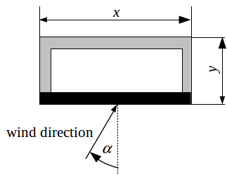
Based on the wind incidence angle α and the side ratio
of the walls, the model computes how much the wind pressure
is attenuated compared to the reference wind pressure Cp0.
The reference wind pressure Cp0 is a user-defined parameter,
and must be equal to the wind pressure at zero wind incidence angle, i.e.,
α = 0.
Swami and Chandra (1987) recommend Cp0 = 0.6 for
all low-rise buildings as this represents the average of
various values reported in the literature.
The attenuation factor is
Cp ⁄ Cp0 = ln(1.248 - 0.703 sin(α ⁄ 2) - 1.175 sin2(α) - 0.131 sin3(2 α G) + 0.769 cos(α ⁄ 2) +0.071 G2 * sin2(α ⁄ 2) + 0.717 cos2(α ⁄ 2)),
where Cp is the wind pressure coefficient for the current angle of incidence.
This function is used in Buildings.Fluid.Sources.Outside_CpLowRise which can be used directly with components of this package.
References
- Muthusamy V. Swami and Subrato Chandra. Procedures for Calculating Natural Ventilation Airflow Rates in Buildings. Florida Solar Energy Center, FSEC-CR-163-86. March, 1987. Cape Canaveral, Florida.
- Andrew K. Persily and Elizabeth M. Ivy. Input Data for Multizone Airflow and IAQ Analysis. NIST, NISTIR 6585. January, 2001. Gaithersburg, MD.
Implementation
Symmetry requires that the first derivative of the wind pressure coefficient with respect to the incidence angle is zero for incidence angles of zero and π. However, the correlation of Swami and Chandra has non-zero derivatives at these values. In this implementation, the original function is therefore slightly modified for incidence angles between 0 and 5 degree, and between 175 and 180 degree. This leads to a model that is differentiable in the incidence angle, which generally leads to better numeric performance.
Inputs
| Type | Name | Default | Description |
|---|---|---|---|
| Real | Cp0 | Wind pressure coefficient for normal wind incidence angle | |
| Angle | incAng | Wind incidence angle (0: normal to wall) [rad] | |
| Real | G | Natural logarithm of side ratio |
Outputs
| Type | Name | Description |
|---|---|---|
| Real | Cp | Wind pressure coefficient |