Buildings.Airflow.Multizone
Package with models for multizone airflow and contaminant transport
Information
This package provides models to compute the airflow and contaminant transport between different rooms and between a room and the exterior environment. See the User's Guide for more information.Extends from Modelica.Icons.VariantsPackage (Icon for package containing variants).
Package Content
| Name | Description |
|---|---|
| User's Guide | |
| Door model using discretization along height coordinate | |
| Door model using discretization along height coordinate | |
| Door model for bi-directional air flow between rooms | |
| Door model for bi-directional air flow between rooms that can be open or closed | |
| Effective air leakage area | |
| Vertical shaft with no friction and no storage of heat and mass | |
| Vertical shaft with no friction and storage of heat and mass | |
| Orifice | |
| Zonal flow with input air change per second | |
| Zonal flow with input air change per second | |
| Package with type definitions | |
| Collection of models that illustrate model use and test models | |
| Collection of validation models | |
| Package with base classes for Buildings.Airflow.Multizone |
 Buildings.Airflow.Multizone.DoorDiscretizedOpen
Door model using discretization along height coordinate

Information
This model describes the bi-directional air flow through an open door.
To compute the bi-directional flow, the door is discretize along the height coordinate. An orifice equation is used to compute the flow for each compartment.
In this model, the door is always open. Use the model Buildings.Airflow.Multizone.DoorDiscretizedOperable for a door that can either be open or closed.
Extends from Buildings.Airflow.Multizone.BaseClasses.DoorDiscretized (Door model using discretization along height coordinate).
Parameters
| Type | Name | Default | Description |
|---|---|---|---|
| replaceable package Medium | PartialMedium | Medium in the component | |
| Velocity | vZer | 0.001 | Minimum velocity to prevent zero flow. Recommended: 0.001 [m/s] |
| Integer | nCom | 10 | Number of compartments for the discretization |
| PressureDifference | dp_turbulent | 0.01 | Pressure difference where laminar and turbulent flow relation coincide. Recommended: 0.01 [Pa] |
| Geometry | |||
| Length | wOpe | 0.9 | Width of opening [m] |
| Length | hOpe | 2.1 | Height of opening [m] |
| Length | hA | 2.7/2 | Height of reference pressure zone A [m] |
| Length | hB | 2.7/2 | Height of reference pressure zone B [m] |
| Orifice characteristics | |||
| Real | CD | 0.65 | Discharge coefficient |
| Advanced | |||
| Diagnostics | |||
| Boolean | show_T | false | = true, if actual temperature at port is computed |
| Boolean | forceErrorControlOnFlow | true | Flag to force error control on m_flow. Set to true if interested in flow rate |
Connectors
| Type | Name | Description |
|---|---|---|
| FluidPort_a | port_a1 | Fluid connector a1 (positive design flow direction is from port_a1 to port_b1) |
| FluidPort_b | port_b1 | Fluid connector b1 (positive design flow direction is from port_a1 to port_b1) |
| FluidPort_a | port_a2 | Fluid connector a2 (positive design flow direction is from port_a2 to port_b2) |
| FluidPort_b | port_b2 | Fluid connector b2 (positive design flow direction is from port_a2 to port_b2) |
Modelica definition
 Buildings.Airflow.Multizone.DoorDiscretizedOperable
Door model using discretization along height coordinate

Information
This model describes the bi-directional air flow through an open door.
To compute the bi-directional flow, the door is discretize along the height coordinate, and uses an orifice equation to compute the flow for each compartment.
The door can be either open or closed, depending on the input signal y. Set y=0 if the door is closed, and y=1 if the door is open. Use the model Buildings.Airflow.Multizone.DoorDiscretizedOpen for a door that is always closed.
Extends from Buildings.Airflow.Multizone.BaseClasses.DoorDiscretized (Door model using discretization along height coordinate).
Parameters
| Type | Name | Default | Description |
|---|---|---|---|
| replaceable package Medium | PartialMedium | Medium in the component | |
| Velocity | vZer | 0.001 | Minimum velocity to prevent zero flow. Recommended: 0.001 [m/s] |
| Integer | nCom | 10 | Number of compartments for the discretization |
| PressureDifference | dp_turbulent | 0.01 | Pressure difference where laminar and turbulent flow relation coincide. Recommended: 0.01 [Pa] |
| Geometry | |||
| Length | wOpe | 0.9 | Width of opening [m] |
| Length | hOpe | 2.1 | Height of opening [m] |
| Length | hA | 2.7/2 | Height of reference pressure zone A [m] |
| Length | hB | 2.7/2 | Height of reference pressure zone B [m] |
| Rating conditions | |||
| PressureDifference | dpCloRat | 4 | Pressure drop at rating condition of closed door [Pa] |
| Real | CDCloRat | 1 | Discharge coefficient at rating conditions of closed door |
| Closed door | |||
| Area | LClo | Effective leakage area of closed door [m2] | |
| Real | CDClo | 0.65 | Discharge coefficient of closed door |
| Real | mClo | 0.65 | Flow exponent for crack of closed door |
| Open door | |||
| Real | CDOpe | 0.65 | Discharge coefficient of open door |
| Real | mOpe | 0.5 | Flow exponent for door of open door |
| Advanced | |||
| Diagnostics | |||
| Boolean | show_T | false | = true, if actual temperature at port is computed |
| Boolean | forceErrorControlOnFlow | true | Flag to force error control on m_flow. Set to true if interested in flow rate |
Connectors
| Type | Name | Description |
|---|---|---|
| FluidPort_a | port_a1 | Fluid connector a1 (positive design flow direction is from port_a1 to port_b1) |
| FluidPort_b | port_b1 | Fluid connector b1 (positive design flow direction is from port_a1 to port_b1) |
| FluidPort_a | port_a2 | Fluid connector a2 (positive design flow direction is from port_a2 to port_b2) |
| FluidPort_b | port_b2 | Fluid connector b2 (positive design flow direction is from port_a2 to port_b2) |
| input RealInput | y | Opening signal, 0=closed, 1=open [1] |
Modelica definition
 Buildings.Airflow.Multizone.DoorOpen
Door model for bi-directional air flow between rooms

Information
Model for bi-directional air flow through a large opening such as a door.
In this model, the air flow is composed of two components, a one-directional bulk air flow due to static pressure difference in the adjoining two thermal zones, and a two-directional airflow due to temperature-induced differences in density of the air in the two thermal zones. Although turbulent air flow is a nonlinear phenomenon, the model is based on the simplifying assumption that these two air flow rates can be superposed. (Superposition is only exact for laminar flow.) This assumption is made because it leads to a simple model and because there is significant uncertainty and assumptions anyway in such simplified a model for bidirectional flow through a door.
Main equations
The air flow rate due to static pressure difference is
V̇ab,p = CD w h (2/ρ0)0.5 Δpm,
where V̇ is the volumetric air flow rate, CD is the discharge coefficient, w and h are the width and height of the opening, ρ0 is the mass density at the medium default pressure, temperature and humidity, m is the flow exponent and Δp = pa - pb is the static pressure difference between the thermal zones. For this model explanation, we will assume pa > pb. For turbulent flow, m=1/2 and for laminar flow m=1.
The air flow rate due to temperature difference in the thermal zones is V̇ab,t for flow from thermal zone a to b, and V̇ba,t for air flow rate from thermal zone b to a. The model has two air flow paths to allow bi-directional air flow. The mass flow rates at these two air flow paths are
ṁa1 = ρ0 (+V̇ab,p/2 + V̇ab,t),
and, similarly,
V̇ba = ρ0 (-V̇ab,p/2 + V̇ba,t),
where we simplified the calculation by using the density ρ0. To calculate V̇ba,t, we again use the density ρ0 and because of this simplification, we can write
ṁab,t = -ṁba,t = ρ0 V̇ab,t = -ρ0 V̇ba,t,
from which follows that the neutral height, e.g., the height where the air flow rate due to flow induced by temperature difference is zero, is at h/2. Hence,
V̇ab,t = CD ∫0h/2 w v(z) dz,
where v(z) is the velocity at height z. From the Bernoulli equation, we obtain
v(z) = (2 g z Δρ ⁄ ρ0)1/2.
The density difference can be written as
Δρ = ρa-ρb ≈ ρ0 (Tb - Ta) ⁄ T0,
where we used ρa = p0 /(R Ta) and Ta Tb ≈ T02. Substituting this expression into the integral and integrating from 0 to z yields
V̇ab,t = 1⁄3 CD w h (g h ⁄ (R T0 ρ0))1/2 Δp1/2.
The above equation is equivalent to (6) in Brown and Solvason (1962).
Main assumptions
The main assumptions are as follows:
-
The air flow rates due to static pressure difference and due to temperature-difference can be superposed.
-
For buoyancy-driven air flow, a constant density can be used to convert air volume flow rate to air mass flow rate.
From these assumptions follows that the neutral height for buoyancy-driven air flow is at half of the height of the opening.
Notes
For a more detailed model, use Buildings.Airflow.Multizone.DoorDiscretizedOpen.
References
-
Brown, W.G. and K. R. Solvason.
Natural Convection through rectangular openings in partitions - 1.
Int. Journal of Heat and Mass Transfer.
Vol. 5, p. 859-868. 1962.
doi:10.1016/0017-9310(62)90184-9.
Also available at https://nrc-publications.canada.ca/eng/view/ft/?id=081c0ace-7c31-449c-9b3b-e6c14864b196.
Extends from Buildings.Airflow.Multizone.BaseClasses.Door (Partial door model for bi-directional flow).
Parameters
| Type | Name | Default | Description |
|---|---|---|---|
| replaceable package Medium | PartialMedium | Medium in the component | |
| Geometry | |||
| Length | wOpe | 0.9 | Width of opening [m] |
| Length | hOpe | 2.1 | Height of opening [m] |
| Custom Parameters | |||
| Velocity | vAB | VAB_flow/AOpe | Average velocity from A to B [m/s] |
| Velocity | vBA | VBA_flow/AOpe | Average velocity from B to A [m/s] |
| Orifice characteristics | |||
| Real | CD | 0.65 | Discharge coefficient |
| Real | m | 0.5 | Flow coefficient |
| Advanced | |||
| Diagnostics | |||
| Boolean | show_T | false | = true, if actual temperature at port is computed |
| PressureDifference | dp_turbulent | 0.01 | Pressure difference where laminar and turbulent flow relation coincide [Pa] |
Connectors
| Type | Name | Description |
|---|---|---|
| FluidPort_a | port_a1 | Fluid connector a1 (positive design flow direction is from port_a1 to port_b1) |
| FluidPort_b | port_b1 | Fluid connector b1 (positive design flow direction is from port_a1 to port_b1) |
| FluidPort_a | port_a2 | Fluid connector a2 (positive design flow direction is from port_a2 to port_b2) |
| FluidPort_b | port_b2 | Fluid connector b2 (positive design flow direction is from port_a2 to port_b2) |
Modelica definition
 Buildings.Airflow.Multizone.DoorOperable
Door model for bi-directional air flow between rooms that can be open or closed
Information
Model for bi-directional air flow through a large opening such as a door which can be opened or closed based on the control input signal y.
For the control input signal y=1, this model is identical to Buildings.Airflow.Multizone.DoorOpen, and for y=0, the door is assumed to be closed and the air flow rate is set to the air flow rate through the crack posed by the open door, V̇clo.
The air flow rate for the closed door is computed as
V̇clo = kclo ΔpmClo,
where V̇clo is the volume flow rate, kclo is a flow coefficient and mClo is the flow exponent. The flow coefficient is
kclo = Lclo CDCloRat ΔpRat(0.5-mClo) (2/ρ0)0.5,
where Lclo is the effective air leakage area, CDCloRat is the discharge coefficient at the reference condition, ΔpRat is the pressure drop at the rating condition, and ρ0 is the mass density at the medium default pressure, temperature and humidity.
The effective air leakage area Lclo can be obtained, for example, from the ASHRAE fundamentals (ASHRAE, 1997, p. 25.18). In the ASHRAE fundamentals, the effective air leakage area is based on a reference pressure difference of ΔpRat = 4 Pa and a discharge coefficient of CDCloRat = 1. A similar model is also used in the CONTAM software (Dols and Walton, 2002). Dols and Walton (2002) recommend to use for the flow exponent mClo=0.6 to mClo=0.7 if the flow exponent is not reported with the test results.
For the open door, the air flow rate
V̇ope is computed as described in
Buildings.Airflow.Multizone.DoorOpen
with the parameters CDOpe and mOpe.
The actual air flow rate is computed as
V̇clo = (y-1) V̇clo + y V̇ope,
where y ∈ [0, 1] is the control signal. Note that for values of y that are different from 0 and 1, the model simply interpolates the air flow rate between a fully open and a fully closed door. In practice, the air flow rate would likely increase quickly if the door is slightly opened, and hence we do not claim that the model is accurate for values other than y = 0 and y = 1.
References
- ASHRAE. ASHRAE Fundamentals, American Society of Heating, Refrigeration and Air-Conditioning Engineers, 1997.
- Dols and Walton. W. Stuart Dols and George N. Walton, CONTAMW 2.0 User Manual, Multizone Airflow and Contaminant Transport Analysis Software, Building and Fire Research Laboratory, National Institute of Standards and Technology, Tech. Report NISTIR 6921, November, 2002.
Extends from Buildings.Airflow.Multizone.BaseClasses.Door (Partial door model for bi-directional flow).
Parameters
| Type | Name | Default | Description |
|---|---|---|---|
| replaceable package Medium | PartialMedium | Medium in the component | |
| Geometry | |||
| Length | wOpe | 0.9 | Width of opening [m] |
| Length | hOpe | 2.1 | Height of opening [m] |
| Custom Parameters | |||
| Velocity | vAB | VAB_flow/A | Average velocity from A to B [m/s] |
| Velocity | vBA | VBA_flow/A | Average velocity from B to A [m/s] |
| Open door | |||
| Real | CDOpe | 0.65 | Discharge coefficient of open door |
| Real | mOpe | 0.5 | Flow exponent for door of open door |
| Closed door | |||
| Area | LClo | Effective leakage area of closed door [m2] | |
| Real | mClo | 0.65 | Flow exponent for crack of closed door |
| Closed door rating conditions | |||
| PressureDifference | dpCloRat | 4 | Pressure drop at rating condition of closed door [Pa] |
| Real | CDCloRat | 1 | Discharge coefficient at rating conditions of closed door |
| Advanced | |||
| Diagnostics | |||
| Boolean | show_T | false | = true, if actual temperature at port is computed |
| PressureDifference | dp_turbulent | 0.01 | Pressure difference where laminar and turbulent flow relation coincide [Pa] |
Connectors
| Type | Name | Description |
|---|---|---|
| FluidPort_a | port_a1 | Fluid connector a1 (positive design flow direction is from port_a1 to port_b1) |
| FluidPort_b | port_b1 | Fluid connector b1 (positive design flow direction is from port_a1 to port_b1) |
| FluidPort_a | port_a2 | Fluid connector a2 (positive design flow direction is from port_a2 to port_b2) |
| FluidPort_b | port_b2 | Fluid connector b2 (positive design flow direction is from port_a2 to port_b2) |
| input RealInput | y | Opening signal, 0=closed, 1=open [1] |
Modelica definition
 Buildings.Airflow.Multizone.EffectiveAirLeakageArea
Effective air leakage area

Information
This model describes the one-directional pressure driven air flow through a crack-like opening, using the equation
V̇ = k Δpm,
where V̇ is the volume flow rate, k is a flow coefficient and m is the flow exponent. The flow coefficient is
k = L CD,Rat ΔpRat(0.5-m) (2/ρ0)0.5,
where L is the effective air leakage area, CD,Rat is the discharge coefficient at the reference condition, ΔpRat is the pressure drop at the rating condition, and ρ0 is the mass density at the medium default pressure, temperature and humidity.
The effective air leakage area L can be obtained, for example, from the ASHRAE fundamentals (ASHRAE, 1997, p. 25.18). In the ASHRAE fundamentals, the effective air leakage area is based on a reference pressure difference of ΔpRat = 4 Pa and a discharge coefficient of CD,Rat = 1. A similar model is also used in the CONTAM software (Dols and Walton, 2002). Dols and Walton (2002) recommend to use for the flow exponent m=0.6 to m=0.7 if the flow exponent is not reported with the test results.
References
- ASHRAE, 1997. ASHRAE Fundamentals, American Society of Heating, Refrigeration and Air-Conditioning Engineers, 1997.
- Dols and Walton, 2002. W. Stuart Dols and George N. Walton, CONTAMW 2.0 User Manual, Multizone Airflow and Contaminant Transport Analysis Software, Building and Fire Research Laboratory, National Institute of Standards and Technology, Tech. Report NISTIR 6921, November, 2002.
Extends from Buildings.Airflow.Multizone.BaseClasses.PowerLawResistance (Flow resistance that uses the power law).
Parameters
| Type | Name | Default | Description |
|---|---|---|---|
| replaceable package Medium | PartialMedium | Medium in the component | |
| Real | m | 0.65 | Flow exponent, m=0.5 for turbulent, m=1 for laminar |
| Area | L | Effective leakage area [m2] | |
| Rating conditions | |||
| PressureDifference | dpRat | 4 | Pressure drop [Pa] |
| Real | CDRat | 1 | Discharge coefficient |
| Advanced | |||
| Diagnostics | |||
| Boolean | show_T | false | = true, if actual temperature at port is computed |
| Boolean | forceErrorControlOnFlow | true | Flag to force error control on m_flow. Set to true if interested in flow rate |
| Boolean | useDefaultProperties | true | Set to false to use density and viscosity based on actual medium state, rather than using default values |
| PressureDifference | dp_turbulent | 0.1 | Pressure difference where laminar and turbulent flow relation coincide. Recommended = 0.1 [Pa] |
Connectors
| Type | Name | Description |
|---|---|---|
| FluidPort_a | port_a | Fluid connector a (positive design flow direction is from port_a to port_b) |
| FluidPort_b | port_b | Fluid connector b (positive design flow direction is from port_a to port_b) |
Modelica definition
 Buildings.Airflow.Multizone.MediumColumn
Vertical shaft with no friction and no storage of heat and mass

Information
This model describes the pressure difference of a vertical medium column. It can be used to model the pressure difference caused by stack effect.
Typical use and important parameters
The model can be used with the following three configurations, which are
controlled by the setting of the parameter densitySelection:
-
top: Use this setting to use the density from the volume that is connected toport_a. -
bottom: Use this setting to use the density from the volume that is connected toport_b. -
actual: Use this setting to use the density based on the actual flow direction.
The settings top and bottom
should be used when rooms or different floors of a building are
connected since multizone airflow models assume that each floor is completely mixed.
For these two seetings, this model will compute the pressure between the center of the room
and an opening that is at height h relative to the center of the room.
The setting actual may be used to model a chimney in which
a column of air will change its density based on the flow direction.
In this model, the parameter h must always be positive, and the port port_a must be
at the top of the column.
Dynamics
For a dynamic model, use Buildings.Airflow.Multizone.MediumColumnDynamic instead of this model.
Parameters
| Type | Name | Default | Description |
|---|---|---|---|
| replaceable package Medium | Modelica.Media.Interfaces.Pa... | Medium in the component | |
| Length | h | 3 | Height of shaft [m] |
| densitySelection | densitySelection | Select how to pick density | |
Connectors
| Type | Name | Description |
|---|---|---|
| replaceable package Medium | Medium in the component | |
| FluidPort_a | port_a | Fluid connector a (positive design flow direction is from port_a to port_b) |
| FluidPort_b | port_b | Fluid connector b (positive design flow direction is from port_a to port_b) |
Modelica definition
 Buildings.Airflow.Multizone.MediumColumnDynamic
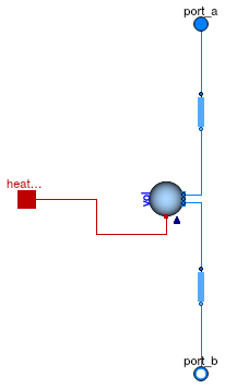
Vertical shaft with no friction and storage of heat and mass
Information
This model contains a completely mixed fluid volume and models that take into account the pressure difference of a medium column that is at the same temperature as the fluid volume. It can be used to model the pressure difference caused by a stack effect.
Typical use and important parameters
Set the parameter use_HeatTransfer=true to expose
a heatPort. This heatPort can be used
to add or subtract heat from the volume. This allows, for example,
to use this model in conjunction with a model for heat transfer through
walls to model a solar chimney that stores heat.
Dynamics
For a steady-state model, use Buildings.Airflow.Multizone.MediumColumn instead of this model.
In this model, the parameter h must always be positive, and the port port_a must be
at the top of the column.
Extends from Buildings.Fluid.Interfaces.LumpedVolumeDeclarations (Declarations for lumped volumes).
Parameters
| Type | Name | Default | Description |
|---|---|---|---|
| replaceable package Medium | PartialMedium | Medium in the component | |
| Length | h | 3 | Height of shaft [m] |
| Volume | V | Volume in medium shaft [m3] | |
| Dynamics | |||
| Equations | |||
| Dynamics | energyDynamics | Modelica.Fluid.Types.Dynamic... | Type of energy balance: dynamic (3 initialization options) or steady state |
| Dynamics | massDynamics | energyDynamics | Type of mass balance: dynamic (3 initialization options) or steady state |
| Real | mSenFac | 1 | Factor for scaling the sensible thermal mass of the volume |
| Initialization | |||
| AbsolutePressure | p_start | Medium.p_default | Start value of pressure [Pa] |
| Temperature | T_start | Medium.T_default | Start value of temperature [K] |
| MassFraction | X_start[Medium.nX] | Medium.X_default | Start value of mass fractions m_i/m [kg/kg] |
| ExtraProperty | C_start[Medium.nC] | fill(0, Medium.nC) | Start value of trace substances |
| ExtraProperty | C_nominal[Medium.nC] | fill(1E-2, Medium.nC) | Nominal value of trace substances. (Set to typical order of magnitude.) |
| Assumptions | |||
| Heat transfer | |||
| Boolean | use_HeatTransfer | false | = true to use the HeatTransfer model |
| replaceable model HeatTransfer | Modelica.Fluid.Vessels.BaseC... | Wall heat transfer | |
Connectors
| Type | Name | Description |
|---|---|---|
| replaceable package Medium | Medium in the component | |
| FluidPort_a | port_a | Fluid connector a (positive design flow direction is from port_a to port_b) |
| FluidPort_b | port_b | Fluid connector b (positive design flow direction is from port_a to port_b) |
| HeatPort_a | heatPort | Heat port to exchange energy with the fluid volume |
| Assumptions | ||
| Heat transfer | ||
| replaceable model HeatTransfer | Wall heat transfer | |
Modelica definition
 Buildings.Airflow.Multizone.Orifice
Orifice

Information
This model describes the mass flow rate and pressure difference relation of an orifice in the form
V̇ = k Δpm,
where V̇ is the volume flow rate, k is a flow coefficient and m is the flow exponent. The flow coefficient is
k = CD A (2/ρ0)0.5,
where CD is the discharge coefficient, A is the cross section area and ρ0 is the mass density at the medium default pressure, temperature and humidity.
For turbulent flow, set m=1/2 and for laminar flow, set m=1. Large openings are characterized by values close to 0.5, while values near 0.65 have been found for small crack-like openings (Dols and Walton, 2002).
References
- W. Stuart Dols and George N. Walton, CONTAMW 2.0 User Manual, Multizone Airflow and Contaminant Transport Analysis Software, Building and Fire Research Laboratory, National Institute of Standards and Technology, Tech. Report NISTIR 6921, November, 2002.
Extends from Buildings.Airflow.Multizone.BaseClasses.PowerLawResistance (Flow resistance that uses the power law).
Parameters
| Type | Name | Default | Description |
|---|---|---|---|
| replaceable package Medium | PartialMedium | Medium in the component | |
| Real | m | 0.5 | Flow exponent, m=0.5 for turbulent, m=1 for laminar |
| Orifice characteristics | |||
| Area | A | Area of orifice [m2] | |
| Real | CD | 0.65 | Discharge coefficient |
| Advanced | |||
| Diagnostics | |||
| Boolean | show_T | false | = true, if actual temperature at port is computed |
| Boolean | forceErrorControlOnFlow | true | Flag to force error control on m_flow. Set to true if interested in flow rate |
| Boolean | useDefaultProperties | true | Set to false to use density and viscosity based on actual medium state, rather than using default values |
| PressureDifference | dp_turbulent | 0.1 | Pressure difference where laminar and turbulent flow relation coincide. Recommended = 0.1 [Pa] |
Connectors
| Type | Name | Description |
|---|---|---|
| FluidPort_a | port_a | Fluid connector a (positive design flow direction is from port_a to port_b) |
| FluidPort_b | port_b | Fluid connector b (positive design flow direction is from port_a to port_b) |
Modelica definition
 Buildings.Airflow.Multizone.ZonalFlow_ACS
Zonal flow with input air change per second
Information
This model computes the air exchange between volumes.
Input is the air change per seconds. The volume flow rate is computed as
V_flow = ACS * V
where ACS is an input and the volume V is a parameter.
Extends from Buildings.Airflow.Multizone.BaseClasses.ZonalFlow (Flow across zonal boundaries of a room).
Parameters
| Type | Name | Default | Description |
|---|---|---|---|
| replaceable package Medium | PartialMedium | ||
| Boolean | useDefaultProperties | false | Set to true to use constant density |
| Volume | V | Volume of room [m3] | |
| Advanced | |||
| Diagnostics | |||
| Boolean | show_T | false | = true, if actual temperature at port is computed |
Connectors
| Type | Name | Description |
|---|---|---|
| FluidPort_a | port_a1 | Fluid connector a1 (positive design flow direction is from port_a1 to port_b1) |
| FluidPort_b | port_b1 | Fluid connector b1 (positive design flow direction is from port_a1 to port_b1) |
| FluidPort_a | port_a2 | Fluid connector a2 (positive design flow direction is from port_a2 to port_b2) |
| FluidPort_b | port_b2 | Fluid connector b2 (positive design flow direction is from port_a2 to port_b2) |
| input RealInput | ACS | Air change per seconds, relative to the smaller of the two volumes |
Modelica definition
 Buildings.Airflow.Multizone.ZonalFlow_m_flow
Zonal flow with input air change per second
Information
This model computes the air exchange between volumes.
Input is the mass flow rate from
port_a1 to port_b1 and from
port_a2 to port_b2.
Extends from Buildings.Airflow.Multizone.BaseClasses.ZonalFlow (Flow across zonal boundaries of a room).
Parameters
| Type | Name | Default | Description |
|---|---|---|---|
| replaceable package Medium | PartialMedium | ||
| Advanced | |||
| Diagnostics | |||
| Boolean | show_T | false | = true, if actual temperature at port is computed |
Connectors
| Type | Name | Description |
|---|---|---|
| FluidPort_a | port_a1 | Fluid connector a1 (positive design flow direction is from port_a1 to port_b1) |
| FluidPort_b | port_b1 | Fluid connector b1 (positive design flow direction is from port_a1 to port_b1) |
| FluidPort_a | port_a2 | Fluid connector a2 (positive design flow direction is from port_a2 to port_b2) |
| FluidPort_b | port_b2 | Fluid connector b2 (positive design flow direction is from port_a2 to port_b2) |
| input RealInput | mAB_flow | Mass flow rate from A to B, positive if flow from port_a1 to port_b1 |
| input RealInput | mBA_flow | Mass flow rate from B to A, positive if flow from port_a2 to port_b2 |