Information
This package contains base classes that are used to construct the models in
Buildings.Fluid.CHPs.
Extends from Modelica.Icons.BasesPackage (Icon for packages containing base classes).
Package Content
| Name |
Description |
 AssertFuelFlow AssertFuelFlow
|
Assert whether fuel flow is within boundary |
| AssertPower
|
Assert if electric power is outside boundaries |
 AssertWaterFlow AssertWaterFlow
|
Assert if water flow is outside boundaries |
 AssertWaterTemperature AssertWaterTemperature
|
Assert if water outlet temperature is outside boundaries |
 Controller Controller
|
Define current operation mode |
 EfficiencyCurve EfficiencyCurve
|
Efficiency curve described by a fifth order polynomial,
function of three input variables |
 EnergyConversion EnergyConversion
|
Energy conversion control volume |
 EnergyConversionNormal EnergyConversionNormal
|
Energy conversion for typical CHP operation either in normal mode or warm-up mode based on time delay |
 EnergyConversionWarmUp EnergyConversionWarmUp
|
Energy conversion during warm-up mode based on engine temperature |
 EngineTemperature EngineTemperature
|
Heat exchange within the engine control volume |
 FilterPower FilterPower
|
Constraints for electric power |
 PowerConsumption PowerConsumption
|
Power consumption during stand-by and cool-down modes |
 WarmUpLeaving WarmUpLeaving
|
Model evaluating the condition for transitioning from warm-up to normal mode |
 WaterFlowControl WaterFlowControl
|
Internal controller for water flow rate |
 Functions Functions
|
|
 Types Types
|
Library of CHP operation modes |
 Validation Validation
|
Validation of the baseclasses |
 Interfaces Interfaces
|
|
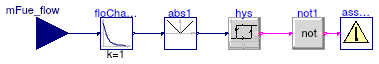
Assert whether fuel flow is within boundary
Information
The model sends a warning message if the rate at which the fuel mass flow rate changes
is outside the boundaries defined by the manufacturer.
Extends from Modelica.Blocks.Icons.Block (Basic graphical layout of input/output block).
Parameters
| Type | Name | Default | Description |
|---|
| Real | dmFueMax_flow | dmFueMax_flow(final unit="kg... | Maximum rate at which fuel mass flow rate can change [kg/s2] |
Connectors
| Type | Name | Description |
|---|
| input RealInput | mFue_flow | Fuel mass flow rate [kg/s] |
Modelica definition
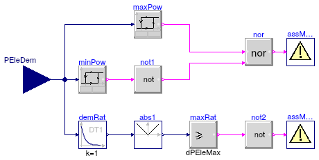
Assert if electric power is outside boundaries
Information
The model sends a warning message if the power demand is outside the boundaries defined by the manufacturer.
Limits can be specified for the minimal and maximal electric power, and for the maximum rate at
which the power can change.
Extends from Modelica.Blocks.Icons.Block (Basic graphical layout of input/output block).
Parameters
| Type | Name | Default | Description |
|---|
| Power | PEleMax | | Maximum power output [W] |
| Power | PEleMin | | Minimum power output [W] |
| Boolean | use_powerRateLimit | | If true, the rate at which net power output can change is limited |
| Real | dPEleMax | dPEleMax(final unit="W/s") | Maximum rate at which net power output can change [W/s] |
Connectors
| Type | Name | Description |
|---|
| input RealInput | PEleDem | Electric power demand [W] |
Modelica definition
model AssertPower
extends Modelica.Blocks.Icons.Block;
parameter Modelica.SIunits.Power PEleMax
;
parameter Modelica.SIunits.Power PEleMin
;
parameter Boolean use_powerRateLimit
;
parameter Real dPEleMax(
final unit="W/s")
;
Buildings.Controls.OBC.CDL.Interfaces.RealInput PEleDem(
final unit="W")
;
Buildings.Controls.OBC.CDL.Utilities.Assert assMesP(
final message="Electric power is outside boundaries!")
;
Buildings.Controls.OBC.CDL.Utilities.Assert assMesDP(
final message="Rate of change in power output is outside boundaries!")
if use_powerRateLimit
;
protected
Buildings.Controls.OBC.CDL.Logical.Nor nor
;
Buildings.Controls.OBC.CDL.Logical.Not not2
if use_powerRateLimit ;
Buildings.Controls.OBC.CDL.Continuous.Derivative demRat(
final x_start=0)
if use_powerRateLimit
;
Buildings.Controls.OBC.CDL.Continuous.Abs abs1
if use_powerRateLimit ;
Buildings.Controls.OBC.CDL.Continuous.GreaterEqualThreshold maxRat(
final threshold=dPEleMax)
if use_powerRateLimit
;
Buildings.Controls.OBC.CDL.Continuous.Hysteresis maxPow(
final uLow=0.99*PEleMax,
final uHigh=1.01*PEleMax + 1e-6)
;
Buildings.Controls.OBC.CDL.Continuous.Hysteresis minPow(
final uLow=0.99*PEleMin - 1e-6,
final uHigh=1.01*PEleMin)
;
Buildings.Controls.OBC.CDL.Logical.Not not1
;
equation
connect(abs1.u, demRat.y);
connect(maxRat.u, abs1.y);
connect(demRat.u, PEleDem);
connect(nor.y, assMesP.u);
connect(not2.y, assMesDP.u);
connect(PEleDem, maxPow.u);
connect(maxPow.y, nor.u1);
connect(PEleDem, minPow.u);
connect(minPow.y, not1.u);
connect(not1.y, nor.u2);
connect(maxRat.y, not2.u);
end AssertPower;
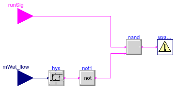
Assert if water flow is outside boundaries
Information
The model sends a warning message if the water mass flow rate is lower than the
minimum defined by the manufacturer.
Extends from Modelica.Blocks.Icons.Block (Basic graphical layout of input/output block).
Parameters
| Type | Name | Default | Description |
|---|
| MassFlowRate | mWatMin_flow | | Minimum cooling water mass flow rate [kg/s] |
Connectors
| Type | Name | Description |
|---|
| input BooleanInput | runSig | True when electricity or heat demand is larger than zero |
| input RealInput | mWat_flow | Water mass flow rate [kg/s] |
Modelica definition
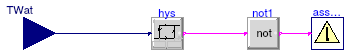
Assert if water outlet temperature is outside boundaries
Information
The model sends a warning message if the water outlet temperature is higher
than the maximum defined by the manufacturer.
Extends from Modelica.Blocks.Icons.Block (Basic graphical layout of input/output block).
Parameters
| Type | Name | Default | Description |
|---|
| Temperature | TWatMax | | Maximum cooling water temperature [K] |
| Advanced |
| TemperatureDifference | THys | 0.5 | Hysteresis value to check temperature difference [K] |
Connectors
| Type | Name | Description |
|---|
| input RealInput | TWat | Water outlet temperature [K] |
Modelica definition
Define current operation mode
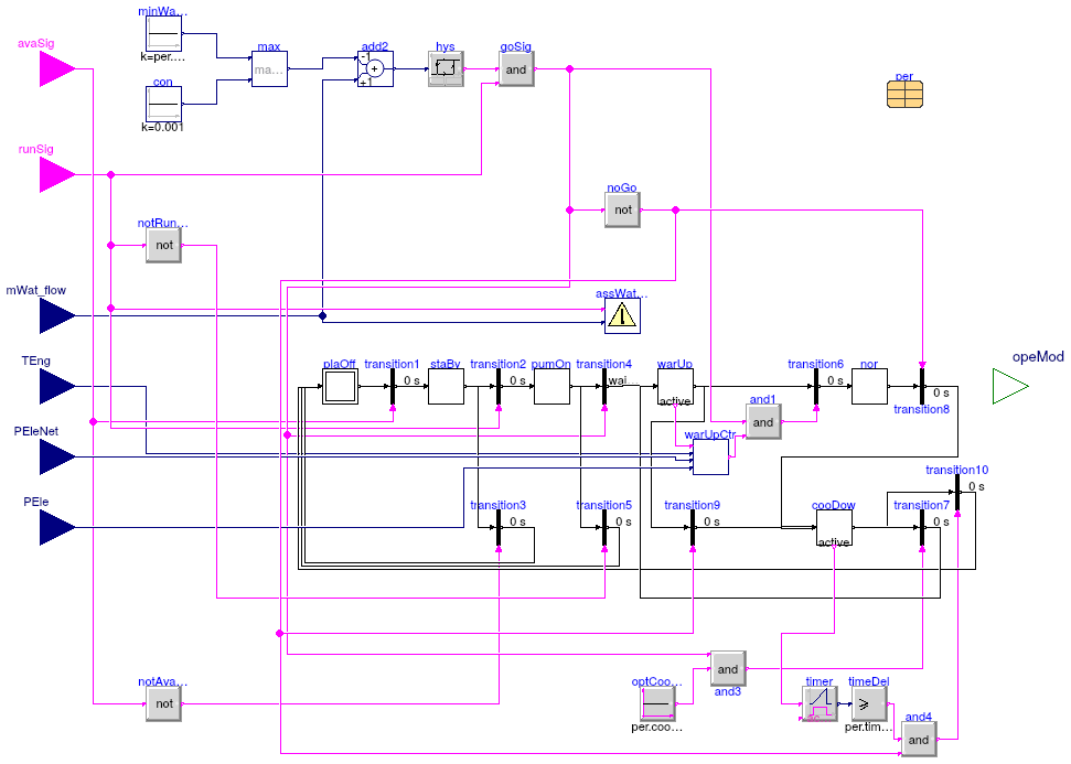
Information
The CHP plant switches between six possible operating modes depending on the current mode,
control signals and plant boundary conditions. The regular transition between them
is as follows:
-
off
-
stand-by mode
-
pump-on mode
-
warm-up mode
-
normal operation
-
cool-down mode
-
off or stand-by mode
Switching between operating modes
From the off mode:
-
The transition from the off to the stand-by mode will occur when the plant availability
signal
avaSig becomes true.
From the stand-by mode:
-
The transition from the stand-by to the pump-on mode will occur when the plant
running signal
runSig becomes true.
-
If
avaSig becomes false, the CHP will automatically change to the off mode.
From the pump-on mode:
-
The transition from the pump-on to stand-by mode will occur after the specified
time delay and if the water flow rate
mWat_flow is greater than
the minimum mWatMin_flow.
-
If
runSig becomes false, the CHP will automatically change to the off mode.
From the warm-up mode:
-
The transition from the warm-up mode to the normal operation will occur after the
specified time delay (if
warmUpByTimeDelay is true)
or when the engine temperature TEng becomes higher than the
nominal temperature TEngNom (if warmUpByTimeDelay
is false).
-
If
runSig becomes false or if the water flow rate mWat_flow
becomes less than the minimum mWatMin_flow, the CHP will automatically
change to the cool-down mode.
From the normal mode:
-
The transition from the normal operation to the cool-down mode will occur when
runSig becomes false or if the water flow rate mWat_flow
becomes less than the minimum mWatMin_flow.
From the cool-down mode:
-
The transition from the cool-down mode will occur after the specified time delay.
If
avaSig is true, the CHP will change to the stand-by mode; else,
it will change to the off mode.
-
If the CHP has the mandatory cool-down configuration (if
coolDownOptional
is false), the plant has to complete the cool-down period before it can be reactivated.
If the CHP has the optional cool-down configuration (if coolDownOptional
is true), the plant may imediatelly change to the warm-up mode if it gets reactivated
(runSig= true).
Extends from Modelica.Blocks.Icons.Block (Basic graphical layout of input/output block).
Parameters
| Type | Name | Default | Description |
|---|
| Generic | per | redeclare parameter Building... | Performance data |
| Dynamics |
| Time | waitTime | 60 | Wait time before transition from pump-on mode fires [s] |
Connectors
Modelica definition
model Controller
extends Modelica.Blocks.Icons.Block;
replaceable parameter Buildings.Fluid.CHPs.Data.Generic per
;
parameter Modelica.SIunits.Time waitTime=60
;
Buildings.Controls.OBC.CDL.Interfaces.BooleanInput avaSig
;
Buildings.Controls.OBC.CDL.Interfaces.BooleanInput runSig
;
Buildings.Controls.OBC.CDL.Interfaces.RealInput mWat_flow(
final unit="kg/s")
;
Buildings.Controls.OBC.CDL.Interfaces.RealInput TEng(
final unit="K",
final displayUnit="degC")
if not per.warmUpByTimeDelay
;
Buildings.Controls.OBC.CDL.Interfaces.RealInput PEleNet(
final unit="W")
if
not per.warmUpByTimeDelay
;
Buildings.Controls.OBC.CDL.Interfaces.RealInput PEle(
final unit="W")
if
not per.warmUpByTimeDelay
;
Buildings.Fluid.CHPs.BaseClasses.Interfaces.ModeTypeOutput opeMod
;
Modelica.StateGraph.Step staBy(nOut=2)
;
Modelica.StateGraph.Step pumOn(nOut=2)
;
Modelica.StateGraph.StepWithSignal warUp(nIn=2, nOut=2)
;
Modelica.StateGraph.StepWithSignal cooDow(nIn=2, nOut=2)
;
protected
Buildings.Controls.OBC.CDL.Continuous.Sources.Constant minWatFlo(
final k=per.mWatMin_flow) ;
Buildings.Controls.OBC.CDL.Continuous.Sources.Constant con(
final k=0.001) ;
Buildings.Controls.OBC.CDL.Continuous.Max max
;
Buildings.Controls.OBC.CDL.Continuous.Add add2(
final k1=-1)
;
Buildings.Controls.OBC.CDL.Continuous.Hysteresis hys(
final uLow=0.01*per.mWatMin_flow - 1e-6,
final uHigh=0.015*per.mWatMin_flow)
;
Buildings.Controls.OBC.CDL.Logical.And goSig
;
Buildings.Controls.OBC.CDL.Logical.Not notRunSig ;
Buildings.Controls.OBC.CDL.Logical.Not notAvaSig ;
Buildings.Controls.OBC.CDL.Logical.And and1
;
Modelica.StateGraph.TransitionWithSignal transition3 ;
Modelica.StateGraph.TransitionWithSignal transition5 ;
Modelica.StateGraph.TransitionWithSignal transition9 ;
Modelica.StateGraph.TransitionWithSignal transition7 ;
Buildings.Controls.OBC.CDL.Logical.And and3
;
Modelica.StateGraph.TransitionWithSignal transition10 ;
Buildings.Controls.OBC.CDL.Logical.And and4
;
Buildings.Fluid.CHPs.BaseClasses.AssertWaterFlow assWatMas(
final mWatMin_flow=per.mWatMin_flow)
;
Buildings.Fluid.CHPs.BaseClasses.Types.Mode actMod ;
Modelica.StateGraph.TransitionWithSignal transition1
;
Modelica.StateGraph.TransitionWithSignal transition2 ;
Modelica.StateGraph.Step nor(
final nIn=1,
final nOut=1)
;
Modelica.StateGraph.TransitionWithSignal transition8 ;
Buildings.Fluid.CHPs.BaseClasses.WarmUpLeaving warUpCtr(
final timeDelayStart=per.timeDelayStart,
final TEngNom=per.TEngNom,
final PEleMax=per.PEleMax,
final warmUpByTimeDelay=per.warmUpByTimeDelay)
;
Modelica.StateGraph.TransitionWithSignal transition6 ;
Modelica.StateGraph.InitialStep plaOff(
final nIn=3) ;
Modelica.StateGraph.TransitionWithSignal transition4(
final enableTimer=true,
final waitTime=waitTime) ;
Buildings.Controls.OBC.CDL.Logical.Sources.Constant optCooDow(
final k=per.coolDownOptional)
;
Buildings.Controls.OBC.CDL.Continuous.GreaterEqualThreshold timeDel(
final threshold=per.timeDelayCool)
;
Buildings.Controls.OBC.CDL.Logical.Timer timer
;
Buildings.Controls.OBC.CDL.Logical.Not noGo ;
equation
if plaOff.active
then
actMod = CHPs.BaseClasses.Types.Mode.Off;
elseif staBy.active
then
actMod = CHPs.BaseClasses.Types.Mode.StandBy;
elseif pumOn.active
then
actMod = CHPs.BaseClasses.Types.Mode.PumpOn;
elseif warUp.active
then
actMod = CHPs.BaseClasses.Types.Mode.WarmUp;
elseif nor.active
then
actMod = CHPs.BaseClasses.Types.Mode.Normal;
else
actMod = CHPs.BaseClasses.Types.Mode.CoolDown;
end if;
opeMod = actMod;
connect(nor.outPort[1], transition8.inPort);
connect(TEng, warUpCtr.TEng);
connect(plaOff.outPort[1], transition1.inPort);
connect(transition6.outPort, nor.inPort[1]);
connect(assWatMas.mWat_flow, mWat_flow);
connect(minWatFlo.y, max.u1);
connect(con.y, max.u2);
connect(max.y, add2.u1);
connect(add2.y, hys.u);
connect(hys.y, goSig.u1);
connect(mWat_flow, add2.u2);
connect(runSig, goSig.u2);
connect(runSig, notRunSig.u);
connect(runSig, assWatMas.runSig);
connect(avaSig, transition1.condition);
connect(runSig, transition2.condition);
connect(avaSig, notAvaSig.u);
connect(goSig.y, transition4.condition);
connect(and1.y, transition6.condition);
connect(notAvaSig.y, transition3.condition);
connect(and3.y, transition7.condition);
connect(and4.y, transition10.condition);
connect(transition3.outPort, plaOff.inPort[1]);
connect(transition5.outPort, plaOff.inPort[2]);
connect(transition10.outPort, plaOff.inPort[3]);
connect(goSig.y, and3.u2);
connect(optCooDow.y, and3.u1);
connect(transition1.outPort, staBy.inPort[1]);
connect(staBy.outPort[1], transition2.inPort);
connect(staBy.outPort[2], transition3.inPort);
connect(transition2.outPort, pumOn.inPort[1]);
connect(pumOn.outPort[1], transition4.inPort);
connect(pumOn.outPort[2], transition5.inPort);
connect(warUp.outPort[1], transition6.inPort);
connect(warUp.outPort[2], transition9.inPort);
connect(warUp.active, warUpCtr.actWarUp);
connect(warUpCtr.y, and1.u2);
connect(goSig.y, and1.u1);
connect(transition4.outPort, warUp.inPort[1]);
connect(transition7.outPort, warUp.inPort[2]);
connect(transition8.outPort, cooDow.inPort[1]);
connect(transition9.outPort, cooDow.inPort[2]);
connect(cooDow.outPort[1], transition10.inPort);
connect(cooDow.outPort[2], transition7.inPort);
connect(timer.y, timeDel.u);
connect(cooDow.active, timer.u);
connect(timeDel.y, and4.u1);
connect(PEleNet, warUpCtr.PEleNet);
connect(PEle, warUpCtr.PEle);
connect(notRunSig.y, transition5.condition);
connect(goSig.y, noGo.u);
connect(noGo.y, transition8.condition);
connect(noGo.y, and4.u2);
connect(noGo.y, transition9.condition);
end Controller;
Efficiency curve described by a fifth order polynomial,
function of three input variables
Information
The block computes the efficiency as a polynomial function of three input variables.
The polynomial has the form
y = a1
+ a2 x12
+ a3 x1
+ a4 x22
+ a5 x2
+ a6 x32
+ a7 x3
+ a8 x12 x22
+ a9 x1 x2
+ a10 x1 x22
+ a11 x12 x2
+ a12 x12 x32
+ a13 x1 x3
+ a14 x1 x32
+ a15 x12 x3
+ a16 x22 x32
+ a17 x2 x3
+ a18 x2 x32
+ a19 x22 x3
+ a20 x12 x22 x32
+ a21 x12 x22 x3
+ a22 x12 x2 x32
+ a23 x1 x22 x32
+ a24 x12 x2 x3
+ a25 x1 x22 x3
+ a26 x1 x2 x32
+ a27 x1 x2 x3
where
x1 is the net power output,
x2 is the water mass flow rate,
x3 is the water inlet temperature.
Extends from Modelica.Blocks.Icons.Block (Basic graphical layout of input/output block).
Parameters
| Type | Name | Default | Description |
|---|
| Real | a[27] | | Polynomial coefficients |
Connectors
| Type | Name | Description |
|---|
| input RealInput | PNet | Electric power [W] |
| input RealInput | mWat_flow | Water mass flow rate [kg/s] |
| input RealInput | TWatIn | Water inlet temperature [K] |
| output RealOutput | eta | Efficiency [1] |
Modelica definition
Energy conversion control volume
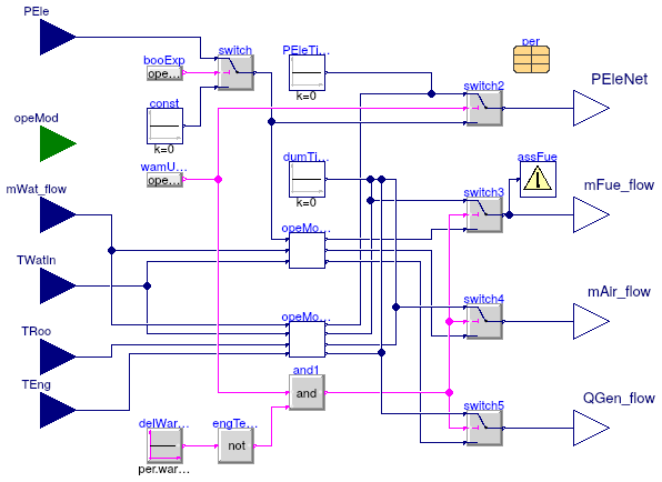
Information
The model defines energy conversion that occurs during the normal mode and warm-up mode.
The model
Buildings.Fluid.CHPs.BaseClasses.EnergyConversionWarmUp
is used only for the
warm-up mode dependent on the engine temperature (case of Stirling engines).
The model
Buildings.Fluid.CHPs.BaseClasses.EnergyConversionNormal
is used for all other cases,
i.e. the normal mode, and the warm-up mode based on a time delay (case of internal
combustion engines).
Extends from Modelica.Blocks.Icons.Block (Basic graphical layout of input/output block).
Parameters
| Type | Name | Default | Description |
|---|
| Generic | per | redeclare parameter Building... | Performance data |
Connectors
Modelica definition
model EnergyConversion
extends Modelica.Blocks.Icons.Block;
replaceable parameter Buildings.Fluid.CHPs.Data.Generic per
;
Buildings.Controls.OBC.CDL.Interfaces.RealInput PEle(
final unit="W") ;
Buildings.Fluid.CHPs.BaseClasses.Interfaces.ModeTypeInput opeMod
;
Buildings.Controls.OBC.CDL.Interfaces.RealInput mWat_flow(
final unit="kg/s",
final quantity="MassFlowRate") ;
Buildings.Controls.OBC.CDL.Interfaces.RealInput TWatIn(
final unit="K",
displayUnit="degC")
;
Buildings.Controls.OBC.CDL.Interfaces.RealInput TRoo(
final unit="K",
displayUnit="degC") ;
Buildings.Controls.OBC.CDL.Interfaces.RealInput TEng(
final unit="K",
displayUnit="degC")
if not per.warmUpByTimeDelay
;
Buildings.Controls.OBC.CDL.Interfaces.RealOutput PEleNet(
final unit="W") ;
Buildings.Controls.OBC.CDL.Interfaces.RealOutput mFue_flow(
final unit="kg/s",
final quantity="MassFlowRate") ;
Buildings.Controls.OBC.CDL.Interfaces.RealOutput mAir_flow(
final unit="kg/s",
final quantity="MassFlowRate") ;
Buildings.Controls.OBC.CDL.Interfaces.RealOutput QGen_flow(
final unit="W")
;
protected
Buildings.Fluid.CHPs.BaseClasses.AssertFuelFlow assFue(
final dmFueMax_flow=per.dmFueMax_flow)
if per.use_fuelRateLimit
;
Buildings.Fluid.CHPs.BaseClasses.EnergyConversionNormal opeModBas(
final per=
per) ;
Buildings.Fluid.CHPs.BaseClasses.EnergyConversionWarmUp opeModWarUpEngTem(
final per=per)
if not per.warmUpByTimeDelay ;
Buildings.Controls.OBC.CDL.Continuous.Sources.Constant const(
final k=0)
;
Buildings.Controls.OBC.CDL.Logical.Switch switch
;
Modelica.Blocks.Sources.BooleanExpression booExp(
final y=opeMod ==CHPs.BaseClasses.Types.Mode.WarmUp
or
opeMod ==CHPs.BaseClasses.Types.Mode.Normal)
;
Buildings.Controls.OBC.CDL.Logical.Switch switch2
;
Buildings.Controls.OBC.CDL.Logical.Switch switch3
;
Buildings.Controls.OBC.CDL.Logical.Switch switch4
;
Buildings.Controls.OBC.CDL.Logical.Switch switch5
;
Buildings.Controls.OBC.CDL.Continuous.Sources.Constant PEleTimeDel(
final k=0)
if
per.warmUpByTimeDelay
;
Buildings.Controls.OBC.CDL.Logical.Sources.Constant delWarUp(
final k=per.warmUpByTimeDelay) ;
Modelica.Blocks.Sources.BooleanExpression wamUpMod(
final y=opeMod == CHPs.BaseClasses.Types.Mode.WarmUp)
;
Buildings.Controls.OBC.CDL.Logical.Not engTemWarUp
;
Buildings.Controls.OBC.CDL.Logical.And and1
;
Buildings.Controls.OBC.CDL.Continuous.Sources.Constant dumTimDel(
final k=0)
if per.warmUpByTimeDelay
;
equation
connect(opeModBas.mWat_flow, mWat_flow);
connect(opeModBas.TWatIn, TWatIn);
connect(opeModWarUpEngTem.TEng, TEng);
connect(opeModWarUpEngTem.TWatIn, TWatIn);
connect(const.y, switch.u3);
connect(PEle, switch.u1);
connect(booExp.y, switch.u2);
connect(switch.y, opeModBas.PEle);
connect(opeModWarUpEngTem.PEleNet, switch2.u1);
connect(switch2.y, PEleNet);
connect(switch3.y, mFue_flow);
connect(switch4.y, mAir_flow);
connect(switch5.y, QGen_flow);
connect(opeModBas.mFue_flow, switch3.u3);
connect(opeModWarUpEngTem.mFue_flow, switch3.u1);
connect(opeModBas.mAir_flow, switch4.u3);
connect(opeModWarUpEngTem.mAir_flow, switch4.u1);
connect(opeModWarUpEngTem.QGen_flow, switch5.u1);
connect(opeModBas.QGen_flow, switch5.u3);
connect(mWat_flow, opeModWarUpEngTem.mWat_flow);
connect(switch3.y, assFue.mFue_flow);
connect(PEleTimeDel.y, switch2.u1);
connect(switch.y, switch2.u3);
connect(TRoo, opeModWarUpEngTem.TRoo);
connect(delWarUp.y, engTemWarUp.u);
connect(engTemWarUp.y, and1.u2);
connect(wamUpMod.y, and1.u1);
connect(and1.y, switch3.u2);
connect(and1.y, switch4.u2);
connect(and1.y, switch5.u2);
connect(wamUpMod.y, switch2.u2);
connect(dumTimDel.y, switch3.u1);
connect(dumTimDel.y, switch4.u1);
connect(dumTimDel.y, switch5.u1);
end EnergyConversion;
Energy conversion for typical CHP operation either in normal mode or warm-up mode based on time delay
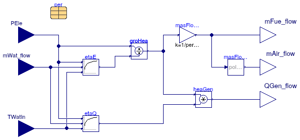
Information
The model defines energy conversion for a typical CHP operation that includes the
normal mode and warm-up mode based on the time delay (CHPs with internal combustion engines).
Energy conversion from fuel to the electric power and heat is modeled using
system's part-load electrical and thermal efficiencies, based on the empirical
data from the manufacturer.
The curves are described by a fifth order polynomial, a function of the electric
power, water flow rate and water inlet temperature.
The air flow rate is modeled using a second order polynomial, a function of
the fuel flow rate.
Extends from Modelica.Blocks.Icons.Block (Basic graphical layout of input/output block).
Parameters
| Type | Name | Default | Description |
|---|
| Generic | per | redeclare parameter Building... | Performance data |
Connectors
| Type | Name | Description |
|---|
| input RealInput | PEle | Electric power [W] |
| input RealInput | mWat_flow | Water mass flow rate [kg/s] |
| input RealInput | TWatIn | Water inlet temperature [K] |
| output RealOutput | mFue_flow | Fuel mass flow rate [kg/s] |
| output RealOutput | mAir_flow | Air mass flow rate [kg/s] |
| output RealOutput | QGen_flow | Heat generation rate within the engine [W] |
Modelica definition
model EnergyConversionNormal
extends Modelica.Blocks.Icons.Block;
replaceable parameter Buildings.Fluid.CHPs.Data.Generic per
;
Buildings.Controls.OBC.CDL.Interfaces.RealInput PEle(
final unit="W") ;
Buildings.Controls.OBC.CDL.Interfaces.RealInput mWat_flow(
final unit="kg/s",
final quantity="MassFlowRate") ;
Buildings.Controls.OBC.CDL.Interfaces.RealInput TWatIn(
final unit="K",
displayUnit="degC") ;
Buildings.Controls.OBC.CDL.Interfaces.RealOutput mFue_flow(
final unit="kg/s",
final quantity="MassFlowRate") ;
Buildings.Controls.OBC.CDL.Interfaces.RealOutput mAir_flow(
final unit="kg/s",
final quantity="MassFlowRate") ;
Buildings.Controls.OBC.CDL.Interfaces.RealOutput QGen_flow(
final unit="W")
;
protected
Buildings.Fluid.CHPs.BaseClasses.EfficiencyCurve etaE(
final a=per.coeEtaE)
;
Buildings.Fluid.CHPs.BaseClasses.EfficiencyCurve etaQ(
final a=per.coeEtaQ)
;
Buildings.Controls.OBC.CDL.Continuous.Division groHea
;
Buildings.Controls.OBC.CDL.Continuous.Product heaGen
;
Buildings.Utilities.Math.Polynominal masFloAir(
final a=per.coeMasAir)
;
Buildings.Controls.OBC.CDL.Continuous.Gain masFloFue(
final k=1/per.LHVFue)
;
equation
connect(groHea.u1, PEle);
connect(heaGen.y, QGen_flow);
connect(QGen_flow, QGen_flow);
connect(masFloAir.y, mAir_flow);
connect(etaE.TWatIn, TWatIn);
connect(etaE.PNet, PEle);
connect(etaQ.PNet, PEle);
connect(mWat_flow, etaE.mWat_flow);
connect(etaQ.mWat_flow, mWat_flow);
connect(etaQ.TWatIn, TWatIn);
connect(etaE.eta, groHea.u2);
connect(etaQ.eta, heaGen.u2);
connect(groHea.y, heaGen.u1);
connect(masFloFue.y, mFue_flow);
connect(groHea.y, masFloFue.u);
connect(masFloFue.y, masFloAir.u);
end EnergyConversionNormal;
Energy conversion during warm-up mode based on engine temperature
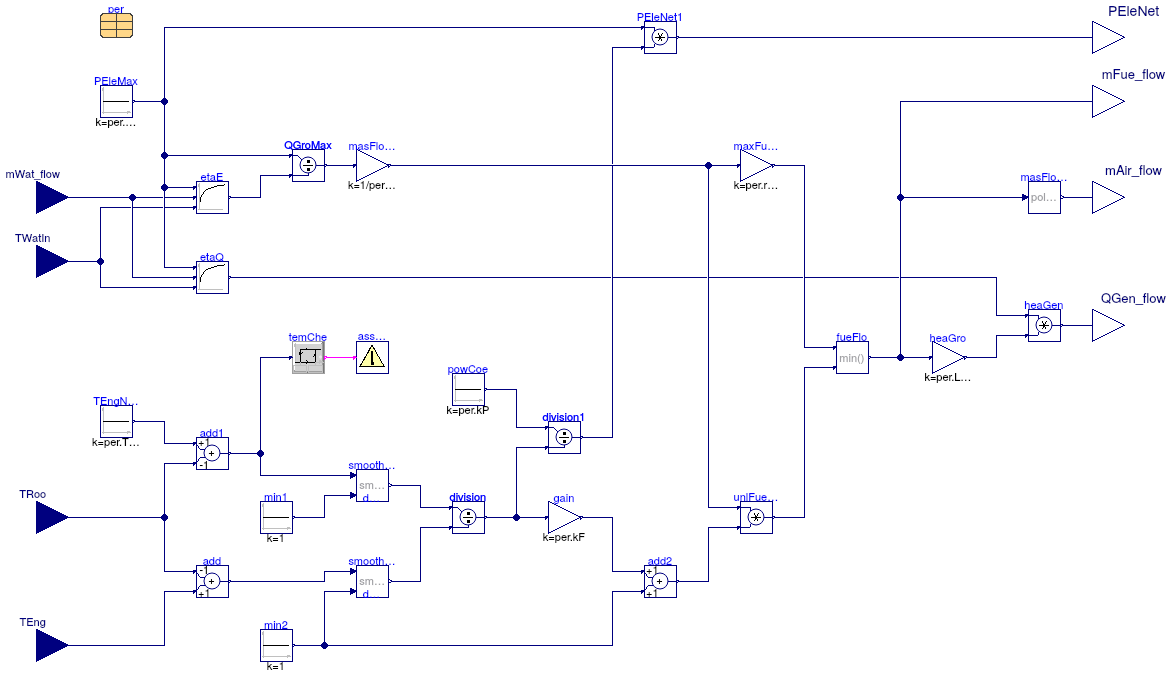
Information
The model defines energy conversion for the warm-up mode that is dependent on the
engine temperature (e.g. CHPs with Stirling engines).
The engine fuel flow rate is a function of the fuel flow rate at the maximum power
output, as well as the difference between the nominal engine temperature and the
actual engine temperature.
Energy conversion from fuel to the electric power and heat is modeled using
system's part-load electrical and thermal efficiencies, based on the empirical
data from the manufacturer.
The curves are described by a fifth order polynomial, a function of the electric
power, water flow rate and water inlet temperature.
The air flow rate is modeled using a second order polynomial, a function of
the fuel flow rate.
Extends from Modelica.Blocks.Icons.Block (Basic graphical layout of input/output block).
Parameters
| Type | Name | Default | Description |
|---|
| Generic | per | redeclare parameter Building... | Performance data |
Connectors
| Type | Name | Description |
|---|
| input RealInput | mWat_flow | Water mass flow rate [kg/s] |
| input RealInput | TWatIn | Water inlet temperature [K] |
| input RealInput | TRoo | Room temperature [K] |
| input RealInput | TEng | Engine temperature [K] |
| output RealOutput | PEleNet | Electric power generation [W] |
| output RealOutput | mFue_flow | Fuel mass flow rate [kg/s] |
| output RealOutput | mAir_flow | Air mass flow rate [kg/s] |
| output RealOutput | QGen_flow | Heat generation rate within the engine [W] |
Modelica definition
model EnergyConversionWarmUp
extends Modelica.Blocks.Icons.Block;
replaceable parameter Buildings.Fluid.CHPs.Data.Generic per
;
Buildings.Controls.OBC.CDL.Interfaces.RealInput mWat_flow(
final unit="kg/s",
final quantity="MassFlowRate") ;
Buildings.Controls.OBC.CDL.Interfaces.RealInput TWatIn(
final unit="K",
displayUnit="degC") ;
Buildings.Controls.OBC.CDL.Interfaces.RealInput TRoo(
final unit="K",
displayUnit="degC") ;
Buildings.Controls.OBC.CDL.Interfaces.RealInput TEng(
final unit="K",
displayUnit="degC") ;
Buildings.Controls.OBC.CDL.Interfaces.RealOutput PEleNet(
final unit="W") ;
Buildings.Controls.OBC.CDL.Interfaces.RealOutput mFue_flow(
final unit="kg/s",
final quantity="MassFlowRate") ;
Buildings.Controls.OBC.CDL.Interfaces.RealOutput mAir_flow(
final unit="kg/s",
final quantity="MassFlowRate") ;
Buildings.Controls.OBC.CDL.Interfaces.RealOutput QGen_flow(
final unit="W")
;
protected
Buildings.Utilities.Math.SmoothMax smoothMax(
final deltaX=0.5)
;
Buildings.Utilities.Math.SmoothMax smoothMax2(
final deltaX=0.5)
;
Buildings.Controls.OBC.CDL.Continuous.Hysteresis temChe(
final uLow=4.8,
final uHigh=5.2)
;
Buildings.Fluid.CHPs.BaseClasses.EfficiencyCurve etaE(
final a=per.coeEtaE) ;
Buildings.Controls.OBC.CDL.Continuous.Division QGroMax
;
Buildings.Controls.OBC.CDL.Continuous.Sources.Constant PEleMax(
final k=per.PEleMax) ;
Buildings.Controls.OBC.CDL.Continuous.Gain maxFueFlo(
final k=per.rFue)
;
Buildings.Controls.OBC.CDL.Continuous.Min fueFlo ;
Buildings.Controls.OBC.CDL.Continuous.Division division
;
Buildings.Controls.OBC.CDL.Continuous.Sources.Constant TEngNom(
y(
final unit="K", displayUnit="degC"),
final k=per.TEngNom) ;
Buildings.Controls.OBC.CDL.Continuous.Add add1(
final k2=-1)
;
Buildings.Controls.OBC.CDL.Continuous.Sources.Constant min1(
final k=1)
;
Buildings.Controls.OBC.CDL.Continuous.Gain gain(
final k=per.kF)
;
Buildings.Controls.OBC.CDL.Continuous.Add add2 ;
Buildings.Controls.OBC.CDL.Continuous.Product unlFueFloWarUp
;
Buildings.Fluid.CHPs.BaseClasses.EfficiencyCurve etaQ(
final a=per.coeEtaQ) ;
Buildings.Controls.OBC.CDL.Continuous.Product heaGen
;
Buildings.Controls.OBC.CDL.Continuous.Division division1
;
Buildings.Controls.OBC.CDL.Continuous.Sources.Constant powCoe(
final k=per.kP) ;
Buildings.Controls.OBC.CDL.Continuous.Product PEleNet1 ;
Buildings.Utilities.Math.Polynominal masFloAir(
final a=per.coeMasAir)
;
Buildings.Controls.OBC.CDL.Continuous.Sources.Constant min2(
final k=1)
;
Buildings.Controls.OBC.CDL.Utilities.Assert assMes(
final message="Room temperature is too close to the nominal engine temperature, simulation should be aborted")
;
Buildings.Controls.OBC.CDL.Continuous.Add add(
final k1=-1)
;
Buildings.Controls.OBC.CDL.Continuous.Gain masFloFue(
final k=1/per.LHVFue)
;
Buildings.Controls.OBC.CDL.Continuous.Gain heaGro(
final k=per.LHVFue)
;
equation
connect(PEleMax.y, etaE.PNet);
connect(QGroMax.u1,PEleMax. y);
connect(etaE.TWatIn, TWatIn);
connect(etaE.mWat_flow, mWat_flow);
connect(etaE.eta, QGroMax.u2);
connect(TEngNom.y, add1.u1);
connect(add1.u2, TRoo);
connect(division.y, gain.u);
connect(gain.y, add2.u1);
connect(add2.y, unlFueFloWarUp.u2);
connect(etaQ.PNet,PEleMax. y);
connect(etaQ.mWat_flow, mWat_flow);
connect(etaQ.TWatIn, TWatIn);
connect(etaQ.eta, heaGen.u1);
connect(maxFueFlo.y, fueFlo.u1);
connect(unlFueFloWarUp.y, fueFlo.u2);
connect(division1.u1,powCoe. y);
connect(division1.u2, division.y);
connect(PEleNet1.u1, PEleMax.y);
connect(PEleNet1.y, PEleNet);
connect(heaGen.y, QGen_flow);
connect(fueFlo.y, mFue_flow);
connect(masFloAir.y, mAir_flow);
connect(min1.y, smoothMax.u2);
connect(add1.y, smoothMax.u1);
connect(smoothMax.y, division.u1);
connect(min2.y, smoothMax2.u2);
connect(smoothMax2.y, division.u2);
connect(temChe.u, add1.y);
connect(division1.y, PEleNet1.u2);
connect(temChe.y, assMes.u);
connect(min2.y, add2.u2);
connect(fueFlo.y,masFloAir. u);
connect(TEng, add.u2);
connect(TRoo, add.u1);
connect(add.y, smoothMax2.u1);
connect(QGroMax.y, masFloFue.u);
connect(masFloFue.y, maxFueFlo.u);
connect(masFloFue.y, unlFueFloWarUp.u1);
connect(heaGro.y, heaGen.u2);
connect(fueFlo.y, heaGro.u);
end EnergyConversionWarmUp;
Heat exchange within the engine control volume
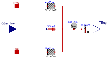
Information
The model defines the dynamic behavior of the CHP thermal mass (i.e. engine block,
encapsulated working fluid, and internal heat exchange equipment) using a single,
engine control volume.
The thermal energy stored within this volume is quantified using an aggregate
thermal capacitance capEng and an equivalent average engine temperature
TEng.
The heat transfer between the engine and the cooling water control volume is
quantified using the overall thermal conductance UAHex,
while the heat loss to the surroundings is quantified using the overall thermal
conductance UALos.
Extends from Modelica.Blocks.Icons.Block (Basic graphical layout of input/output block).
Parameters
| Type | Name | Default | Description |
|---|
| ThermalConductance | UAHex | | Thermal conductance between the engine and cooling water [W/K] |
| ThermalConductance | UALos | | Thermal conductance between the engine and surroundings [W/K] |
| HeatCapacity | capEng | | Thermal capacitance of the engine control volume [J/K] |
| Temperature | TEngIni | | Initial engine temperature [K] |
Connectors
| Type | Name | Description |
|---|
| HeatPort_a | TRoo | Heat port for room temperature |
| input RealInput | QGen_flow | Heat generation rate within the engine [W] |
| HeatPort_a | TWat | Heat port for water volume temperature |
| output RealOutput | TEng | Engine temperature [K] |
Modelica definition
model EngineTemperature
extends Modelica.Blocks.Icons.Block;
parameter Modelica.SIunits.ThermalConductance UAHex
;
parameter Modelica.SIunits.ThermalConductance UALos
;
parameter Modelica.SIunits.HeatCapacity capEng
;
parameter Modelica.SIunits.Temperature TEngIni
;
Modelica.Thermal.HeatTransfer.Interfaces.HeatPort_a TRoo
;
Buildings.Controls.OBC.CDL.Interfaces.RealInput QGen_flow(
final unit="W")
;
Modelica.Thermal.HeatTransfer.Interfaces.HeatPort_a TWat
;
Buildings.Controls.OBC.CDL.Interfaces.RealOutput TEng(
final unit="K",
displayUnit="degC") ;
protected
constant Modelica.SIunits.Density rhoWat=1000 ;
constant Modelica.SIunits.SpecificHeatCapacity cWat=4180 ;
Modelica.Thermal.HeatTransfer.Components.ThermalConductor theConHX(
final G=UAHex)
;
Modelica.Thermal.HeatTransfer.Components.HeatCapacitor capTheEng(
final C=capEng, T(fixed=true, start=TEngIni))
;
Modelica.Thermal.HeatTransfer.Components.ThermalConductor conTheLos(
final G=UALos)
;
Modelica.Thermal.HeatTransfer.Sources.PrescribedHeatFlow QGen1
;
Modelica.Thermal.HeatTransfer.Sensors.TemperatureSensor engTem
;
equation
connect(capTheEng.port, theConHX.port_b);
connect(QGen_flow, QGen1.Q_flow);
connect(conTheLos.port_b, capTheEng.port);
connect(engTem.port, capTheEng.port);
connect(conTheLos.port_a, TRoo);
connect(theConHX.port_a, TWat);
connect(QGen1.port, capTheEng.port);
connect(engTem.T, TEng);
end EngineTemperature;
Constraints for electric power
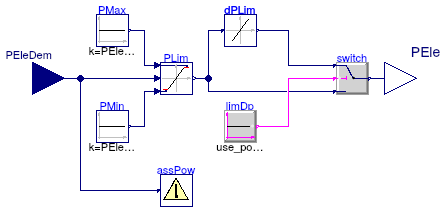
Information
The model checks if the electric power and power rate are within the boundaries
specified by the manufacturer.
The constraints are applied and a warning message is sent if the electric power
is outside the boundaries.
Extends from Modelica.Blocks.Icons.Block (Basic graphical layout of input/output block).
Parameters
| Type | Name | Default | Description |
|---|
| Power | PEleMax | | Maximum power output [W] |
| Power | PEleMin | | Minimum power output [W] |
| Boolean | use_powerRateLimit | | If true, the rate at which net power output can change is limited |
| Real | dPEleMax | dPEleMax(final unit="W/s") | Maximum rate at which net power output can change [W/s] |
Connectors
| Type | Name | Description |
|---|
| input RealInput | PEleDem | Electric power demand [W] |
| output RealOutput | PEle | Electric power demand after applied constraints [W] |
Modelica definition
model FilterPower
extends Modelica.Blocks.Icons.Block;
parameter Modelica.SIunits.Power PEleMax
;
parameter Modelica.SIunits.Power PEleMin
;
parameter Boolean use_powerRateLimit
;
parameter Real dPEleMax(
final unit="W/s")
;
Buildings.Controls.OBC.CDL.Interfaces.RealInput PEleDem(
final unit="W")
;
Buildings.Controls.OBC.CDL.Interfaces.RealOutput PEle(
final unit="W")
;
Buildings.Fluid.CHPs.BaseClasses.AssertPower assPow(
final PEleMax=PEleMax,
final PEleMin=PEleMin,
final use_powerRateLimit=use_powerRateLimit,
final dPEleMax=dPEleMax)
;
protected
Modelica.Blocks.Nonlinear.VariableLimiter PLim ;
Buildings.Controls.OBC.CDL.Continuous.Sources.Constant PMax(
final k=PEleMax) ;
Buildings.Controls.OBC.CDL.Continuous.Sources.Constant PMin(
final k=PEleMin) ;
Buildings.Controls.OBC.CDL.Continuous.SlewRateLimiter dPLim(
final raisingSlewRate(unit="W/s")=dPEleMax,
final fallingSlewRate(unit="W/s")=-dPEleMax,
final Td=1) ;
Buildings.Controls.OBC.CDL.Logical.Switch switch;
Buildings.Controls.OBC.CDL.Logical.Sources.Constant limDp(
final k=use_powerRateLimit)
;
equation
connect(PMax.y, PLim.limit1);
connect(PMin.y, PLim.limit2);
connect(PLim.u, PEleDem);
connect(switch.y, PEle);
connect(PLim.y, dPLim.u);
connect(PLim.y, switch.u3);
connect(assPow.PEleDem, PEleDem);
connect(limDp.y, switch.u2);
connect(dPLim.y, switch.u1);
end FilterPower;
Power consumption during stand-by and cool-down modes
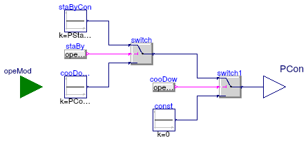
Information
The model calculates the power consumption during the stand-by and cool-down modes of operation.
Extends from Modelica.Blocks.Icons.Block (Basic graphical layout of input/output block).
Parameters
| Type | Name | Default | Description |
|---|
| Power | PStaBy | | Standby electric power [W] |
| Power | PCooDow | | Cooldown electric power [W] |
Connectors
| Type | Name | Description |
|---|
| input ModeTypeInput | opeMod | Operation mode |
| output RealOutput | PCon | Power consumption during stand-by and cool-down modes [W] |
Modelica definition
Model evaluating the condition for transitioning from warm-up to normal mode
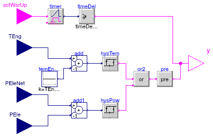
Information
The model computes a boolean variable which is true when warm-up
is over.
CHP will transition from the warm-up mode to the normal mode
-
after the specified time delay if
warmUpByTimeDelay is true, or
-
when the engine temperature exceeds the nominal value or the net power produced
exceeds that requested by the controller if
warmUpByTimeDelay is false.
Extends from Modelica.Blocks.Icons.Block (Basic graphical layout of input/output block).
Parameters
| Type | Name | Default | Description |
|---|
| Time | timeDelayStart | | Time delay between activation and power generation [s] |
| Temperature | TEngNom | | Nominal engine operating temperature [K] |
| Power | PEleMax | 0 | Maximum power output [W] |
| Boolean | warmUpByTimeDelay | | If true, the plant will be in warm-up mode depending on the delay time, otherwise depending on engine temperature |
Connectors
Modelica definition
model WarmUpLeaving
extends Modelica.Blocks.Icons.Block;
parameter Modelica.SIunits.Time timeDelayStart
;
parameter Modelica.SIunits.Temperature TEngNom
;
parameter Modelica.SIunits.Power PEleMax=0
;
parameter Boolean warmUpByTimeDelay
;
Buildings.Controls.OBC.CDL.Interfaces.RealInput TEng(
final unit="K",
displayUnit="degC")
if not warmUpByTimeDelay
;
Buildings.Controls.OBC.CDL.Interfaces.BooleanOutput y ;
Buildings.Controls.OBC.CDL.Interfaces.BooleanInput actWarUp
;
Buildings.Controls.OBC.CDL.Interfaces.RealInput PEle(
final unit="W")
if
not warmUpByTimeDelay
;
Buildings.Controls.OBC.CDL.Interfaces.RealInput PEleNet(
final unit="W")
if
not warmUpByTimeDelay
;
protected
Buildings.Controls.OBC.CDL.Logical.Timer timer
if warmUpByTimeDelay
;
Buildings.Controls.OBC.CDL.Continuous.GreaterEqualThreshold timeDel(
final threshold=timeDelayStart)
if warmUpByTimeDelay
;
Buildings.Controls.OBC.CDL.Continuous.Hysteresis hysTem(uLow=-0.5, uHigh=0)
if
not warmUpByTimeDelay
;
Buildings.Controls.OBC.CDL.Continuous.Add add(
final k2=-1)
if
not warmUpByTimeDelay
;
Buildings.Controls.OBC.CDL.Continuous.Sources.Constant temEngNom(
y(
final unit="K", displayUnit="degC"),
final k=TEngNom)
;
Buildings.Controls.OBC.CDL.Continuous.Add add1(
final k2=-1)
if
not warmUpByTimeDelay
;
Buildings.Controls.OBC.CDL.Continuous.Hysteresis hysPow(
final uLow=-0.01*PEleMax - 1e-6,
final uHigh=0)
if not warmUpByTimeDelay
;
Buildings.Controls.OBC.CDL.Logical.Or or2
if not warmUpByTimeDelay ;
Buildings.Controls.OBC.CDL.Logical.Pre pre
if not warmUpByTimeDelay
;
equation
connect(add.y, hysTem.u);
connect(TEng, add.u1);
connect(temEngNom.y, add.u2);
connect(actWarUp, timer.u);
connect(timer.y, timeDel.u);
connect(add1.y, hysPow.u);
connect(PEle, add1.u2);
connect(hysTem.y, or2.u1);
connect(hysPow.y, or2.u2);
connect(timeDel.y, y);
connect(or2.y, pre.u);
connect(pre.y, y);
connect(PEleNet, add1.u1);
end WarmUpLeaving;
Internal controller for water flow rate
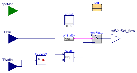
Information
The model calculates the water mass flow rate that is determined by the internal controller.
In CHPs that use this type of internal control the cooling water mass flow rate is
controlled to optimize engine performance and heat recovery.
In the main model of the CHP unit
Buildings.Fluid.CHPs.ThermalElectricalFollowing,
this optimum water mass flow rate is specified as the set point signal for the external pump controller.
Implementation
The mass flow rate is computed as a biquadratic function of the net power output of
the system and the water inlet temperature. Note that
this implementation is a truncated version of the empirical correlation proposed
in Beausoleil-Morrison (2007) which includes terms of higher order (up to four).
References
Beausoleil-Morrison, Ian and Kelly, Nick, 2007. Specifications for modelling fuel cell
and combustion-based residential cogeneration device within whole-building simulation
programs, Section III.
[Report]
Extends from Modelica.Blocks.Icons.Block (Basic graphical layout of input/output block).
Parameters
| Type | Name | Default | Description |
|---|
| Generic | per | redeclare parameter Building... | Performance data |
Connectors
| Type | Name | Description |
|---|
| input ModeTypeInput | opeMod | Operation mode |
| input RealInput | PEle | Electric power [W] |
| input RealInput | TWatIn | Water inlet temperature [K] |
| output RealOutput | mWatSet_flow | Water mass flow rate set point [kg/s] |
Modelica definition
 Buildings.Fluid.CHPs.BaseClasses.AssertFuelFlow
 Buildings.Fluid.CHPs.BaseClasses.AssertWaterFlow
 Buildings.Fluid.CHPs.BaseClasses.AssertWaterTemperature
 Buildings.Fluid.CHPs.BaseClasses.Controller
 Buildings.Fluid.CHPs.BaseClasses.EfficiencyCurve
 Buildings.Fluid.CHPs.BaseClasses.EnergyConversion
 Buildings.Fluid.CHPs.BaseClasses.EnergyConversionNormal
 Buildings.Fluid.CHPs.BaseClasses.EnergyConversionWarmUp
 Buildings.Fluid.CHPs.BaseClasses.EngineTemperature
 Buildings.Fluid.CHPs.BaseClasses.FilterPower
 Buildings.Fluid.CHPs.BaseClasses.PowerConsumption
 Buildings.Fluid.CHPs.BaseClasses.WarmUpLeaving
 Buildings.Fluid.CHPs.BaseClasses.WaterFlowControl