Buildings.Examples.VAVReheat.Validation
Collection of validation models
Information
This package contains validation models for the classes in Buildings.Examples.VAVReheat.
Note that most validation models contain simple input data which may not be realistic, but for which the correct output can be obtained through an analytic solution. The examples plot various outputs, which have been verified against these solutions. These model outputs are stored as reference data and used for continuous validation whenever models in the library change.
Extends from Modelica.Icons.ExamplesPackage (Icon for packages containing runnable examples).
Package Content
| Name | Description |
|---|---|
| Validation of detailed model that is at steady state with constant weather data |
 Buildings.Examples.VAVReheat.Validation.Guideline36SteadyState
Validation of detailed model that is at steady state with constant weather data

Information
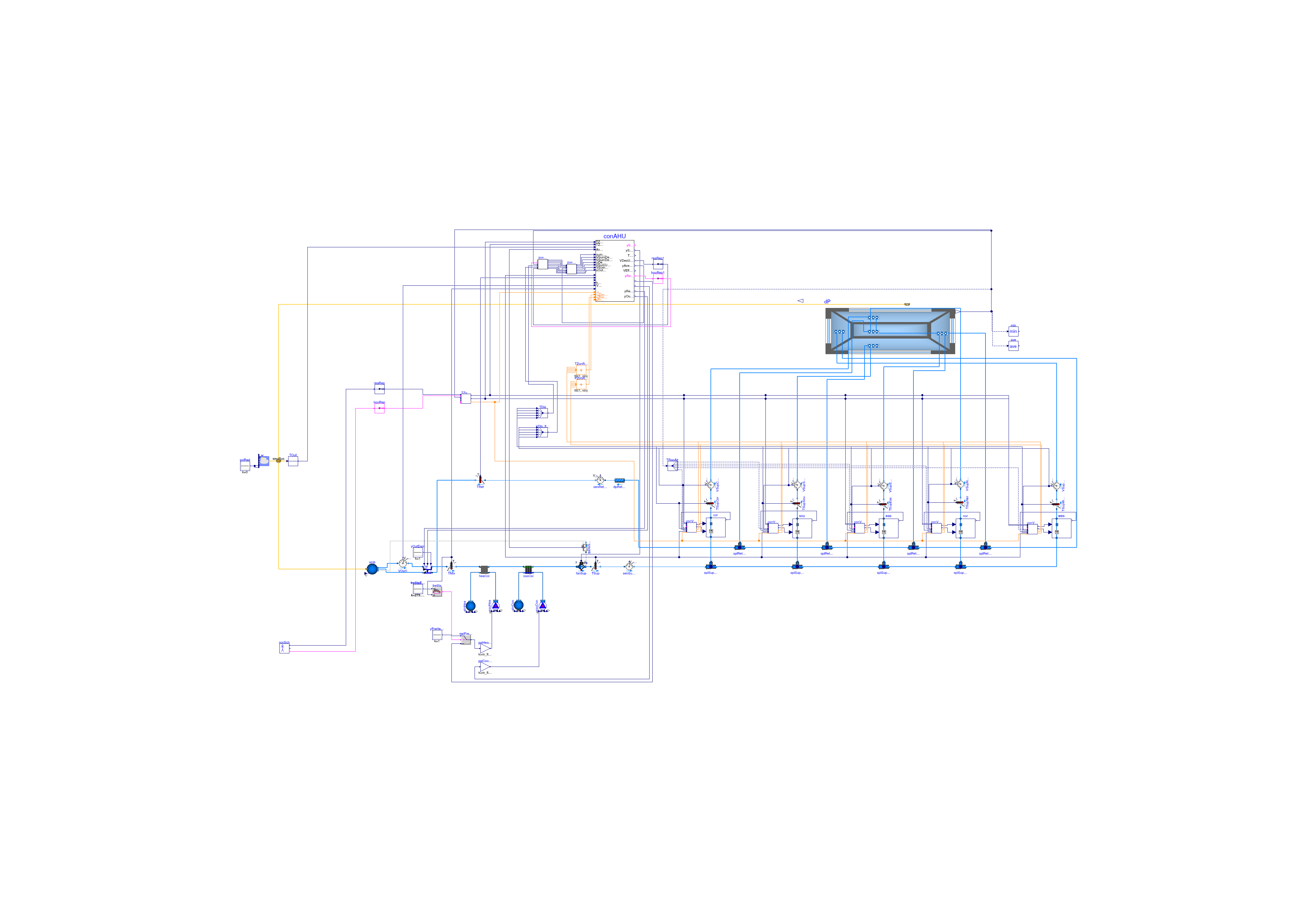
This model validates that the detailed model of multiple rooms and an HVAC system starts at and remains at exactly 20°C room air temperature if there is no solar radiation, constant outdoor conditions, no internal gains and no HVAC operation.
Extends from Buildings.Examples.VAVReheat.Guideline36 (Variable air volume flow system with terminal reheat and five thermal zones).
Parameters
| Type | Name | Default | Description |
|---|---|---|---|
| Volume | VRooCor | AFloCor*flo.hRoo | Room volume corridor [m3] |
| Volume | VRooSou | AFloSou*flo.hRoo | Room volume south [m3] |
| Volume | VRooNor | AFloNor*flo.hRoo | Room volume north [m3] |
| Volume | VRooEas | AFloEas*flo.hRoo | Room volume east [m3] |
| Volume | VRooWes | AFloWes*flo.hRoo | Room volume west [m3] |
| Area | AFloCor | flo.cor.AFlo | Floor area corridor [m2] |
| Area | AFloSou | flo.sou.AFlo | Floor area south [m2] |
| Area | AFloNor | flo.nor.AFlo | Floor area north [m2] |
| Area | AFloEas | flo.eas.AFlo | Floor area east [m2] |
| Area | AFloWes | flo.wes.AFlo | Floor area west [m2] |
| Area | AFlo[numZon] | {flo.cor.AFlo,flo.sou.AFlo,f... | Floor area of each zone [m2] |
| MassFlowRate | mCor_flow_nominal | 6*VRooCor*conv | Design mass flow rate core [kg/s] |
| MassFlowRate | mSou_flow_nominal | 6*VRooSou*conv | Design mass flow rate perimeter 1 [kg/s] |
| MassFlowRate | mEas_flow_nominal | 9*VRooEas*conv | Design mass flow rate perimeter 2 [kg/s] |
| MassFlowRate | mNor_flow_nominal | 6*VRooNor*conv | Design mass flow rate perimeter 3 [kg/s] |
| MassFlowRate | mWes_flow_nominal | 7*VRooWes*conv | Design mass flow rate perimeter 4 [kg/s] |
| MassFlowRate | m_flow_nominal | 0.7*(mCor_flow_nominal + mSo... | Nominal mass flow rate [kg/s] |
| Angle | lat | 41.98*3.14159/180 | Latitude [rad] |
| Temperature | THeaOn | 293.15 | Heating setpoint during on [K] |
| Temperature | THeaOff | 285.15 | Heating setpoint during off [K] |
| Temperature | TCooOn | 297.15 | Cooling setpoint during on [K] |
| Temperature | TCooOff | 303.15 | Cooling setpoint during off [K] |
| PressureDifference | dpBuiStaSet | 12 | Building static pressure [Pa] |
| Real | yFanMin | 0.1 | Minimum fan speed |
| Boolean | allowFlowReversal | true | = false to simplify equations, assuming, but not enforcing, no flow reversal |
| Boolean | use_windPressure | false | Set to true to enable wind pressure |
| VolumeFlowRate | VPriSysMax_flow | m_flow_nominal/1.2 | Maximum expected system primary airflow rate at design stage [m3/s] |
| VolumeFlowRate | minZonPriFlo[numZon] | {mCor_flow_nominal,mSou_flow... | Minimum expected zone primary flow rate [m3/s] |
| Time | samplePeriod | 120 | Sample period of component, set to the same value as the trim and respond that process yPreSetReq [s] |
| PressureDifference | dpDisRetMax | 40 | Maximum return fan discharge static pressure setpoint [Pa] |
| Experimental (may be changed in future releases) | |||
| Boolean | sampleModel | false | Set to true to time-sample the model, which can give shorter simulation time if there is already time sampling in the system model |
Connectors
| Type | Name | Description |
|---|---|---|
| Bus | weaBus | Weather Data Bus |
