Buildings.Controls.OBC.CDL.Logical.Validation
Collection of models that validate the logical blocks of the CDL
Information
This package contains models that validate the blocks in Buildings.Controls.OBC.CDL.Logical.
The examples plot various outputs, which have been verified against analytical solutions. These model outputs are stored as reference data to allow continuous validation whenever models in the library change.
Package Content
| Name | Description |
|---|---|
| Validation model for the And block | |
| Validation model for the And3 block | |
| Validation model for the Change block. | |
| Validation model for the Edge block | |
| Validation model for the falling edge block | |
| Validation model for the IntegerSwitch block | |
| Validation model for the Latch block | |
| Validation model for the LogicalSwitch block | |
| Model to validate the application of MultiAnd block | |
| Model to validate the application of MultiOr block | |
| Validation model for the Nand block | |
| Validation model for the Nor block | |
| Validation model for the Not block | |
| Validation model for the OnOffController block | |
| Validation model for the Or block | |
| Validation model for the Or3 block | |
| Validation model for the Switch block | |
| Validation model for the Timer block | |
| Validation model for the Toggle block | |
| Validation model for the TriggeredTrapezoid block | |
| Validation model for the TrueDelay block | |
| Validation model for the TrueFalseHold block | |
| Validation model for the TrueHoldWithReset block | |
| Validation model for the Xor block | |
| Validation model for the zero crossing block |
 Buildings.Controls.OBC.CDL.Logical.Validation.And
Validation model for the And block
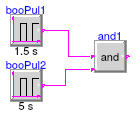
Information
Validation test for the block Buildings.Controls.OBC.CDL.Logical.And.
Modelica definition
 Buildings.Controls.OBC.CDL.Logical.Validation.And3
Validation model for the And3 block
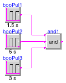
Information
Validation test for the block Buildings.Controls.OBC.CDL.Logical.And3.
Modelica definition
 Buildings.Controls.OBC.CDL.Logical.Validation.Change
Validation model for the Change block.
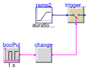
Information
Validation test for the block Buildings.Controls.OBC.CDL.Logical.Change.
Modelica definition
 Buildings.Controls.OBC.CDL.Logical.Validation.Edge
Validation model for the Edge block
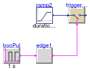
Information
Validation test for the block Buildings.Controls.OBC.CDL.Logical.Edge.
Modelica definition
 Buildings.Controls.OBC.CDL.Logical.Validation.FallingEdge
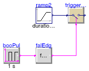
Validation model for the falling edge block
Information
Validation test for the block Buildings.Controls.OBC.CDL.Logical.FallingEdge.
Modelica definition
 Buildings.Controls.OBC.CDL.Logical.Validation.IntegerSwitch
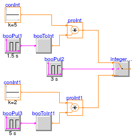
Validation model for the IntegerSwitch block
Information
Validation test for the block Buildings.Controls.OBC.CDL.Logical.IntegerSwitch.
The input u2 is the switch input: If u2 = true,
then output y = u1;
else output y = u3.
Modelica definition
 Buildings.Controls.OBC.CDL.Logical.Validation.Latch
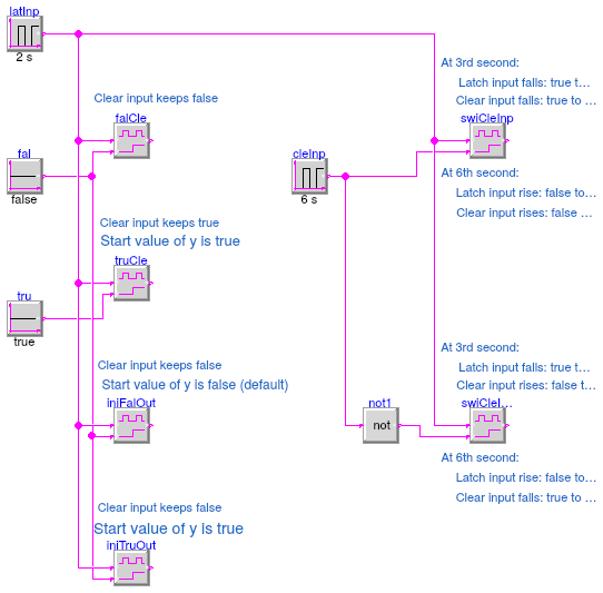
Validation model for the Latch block
Information
Validation test for the block Buildings.Controls.OBC.CDL.Logical.Latch.
Modelica definition
 Buildings.Controls.OBC.CDL.Logical.Validation.LogicalSwitch
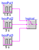
Validation model for the LogicalSwitch block
Information
Validation test for the block Buildings.Controls.OBC.CDL.Logical.LogicalSwitch.
The input u2 is the switch input: If u2 = true,
then output y = u1;
else output y = u3.
Modelica definition
 Buildings.Controls.OBC.CDL.Logical.Validation.MultiAnd
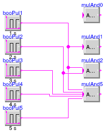
Model to validate the application of MultiAnd block
Information
Validation test for the block Buildings.Controls.OBC.CDL.Logical.MultiAnd.
The input signals are configured as follows:
- input u1 has a period of 1 s and a width of 0.5 s.
- input u2 has a period of 2 s and a width of 0.5 s.
- input u3 has a period of 3 s and a width of 0.5 s.
- input u4 has a period of 4 s and a width of 0.5 s.
- input u5 has a period of 5 s and a width of 0.5 s.
Modelica definition
 Buildings.Controls.OBC.CDL.Logical.Validation.MultiOr
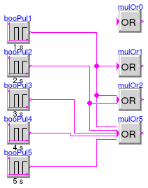
Model to validate the application of MultiOr block
Information
Validation test for the block Buildings.Controls.OBC.CDL.Logical.MultiOr.
The input signals are configured as follows:
- input u1 has a period of 1 s and a width of 0.5 s.
- input u2 has a period of 2 s and a width of 0.5 s.
- input u3 has a period of 3 s and a width of 0.5 s.
- input u4 has a period of 4 s and a width of 0.5 s.
- input u5 has a period of 5 s and a width of 0.5 s.
Modelica definition
 Buildings.Controls.OBC.CDL.Logical.Validation.Nand
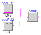
Validation model for the Nand block
Information
Validation test for the block Buildings.Controls.OBC.CDL.Logical.Nand.
Modelica definition
 Buildings.Controls.OBC.CDL.Logical.Validation.Nor
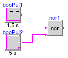
Validation model for the Nor block
Information
Validation test for the block Buildings.Controls.OBC.CDL.Logical.Nor.
Modelica definition
 Buildings.Controls.OBC.CDL.Logical.Validation.Not
Validation model for the Not block

Information
Validation test for the block Buildings.Controls.OBC.CDL.Logical.Not.
Modelica definition
 Buildings.Controls.OBC.CDL.Logical.Validation.OnOffController
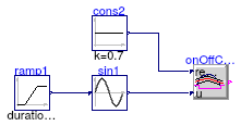
Validation model for the OnOffController block
Information
Validation test for the block Buildings.Controls.OBC.CDL.Logical.OnOffController.
Modelica definition
 Buildings.Controls.OBC.CDL.Logical.Validation.Or
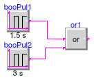
Validation model for the Or block
Information
Validation test for the block Buildings.Controls.OBC.CDL.Logical.Or.
Modelica definition
 Buildings.Controls.OBC.CDL.Logical.Validation.Or3
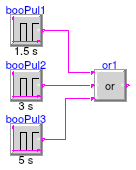
Validation model for the Or3 block
Information
Validation test for the block Buildings.Controls.OBC.CDL.Logical.Or3.
Modelica definition
 Buildings.Controls.OBC.CDL.Logical.Validation.Switch
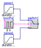
Validation model for the Switch block
Information
Validation test for the block Buildings.Controls.OBC.CDL.Logical.Switch.
Modelica definition
 Buildings.Controls.OBC.CDL.Logical.Validation.Timer
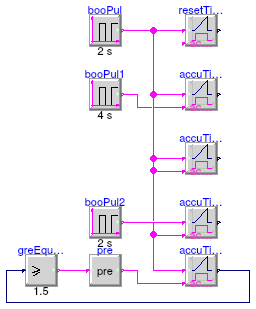
Validation model for the Timer block
Information
Validation test for the block Buildings.Controls.OBC.CDL.Logical.Timer.
Modelica definition
 Buildings.Controls.OBC.CDL.Logical.Validation.Toggle
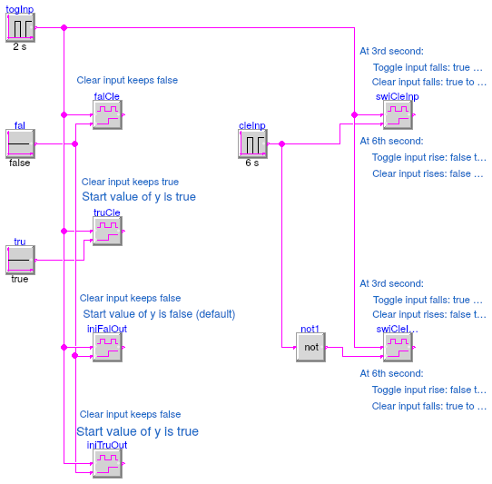
Validation model for the Toggle block
Information
Validation test for the block Buildings.Controls.OBC.CDL.Logical.Toggle.
Modelica definition
 Buildings.Controls.OBC.CDL.Logical.Validation.TriggeredTrapezoid
Validation model for the TriggeredTrapezoid block

Information
Validation test for the block Buildings.Controls.OBC.CDL.Logical.TriggeredTrapezoid.
Modelica definition
 Buildings.Controls.OBC.CDL.Logical.Validation.TrueDelay
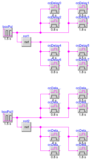
Validation model for the TrueDelay block
Information
Validation test for the block Buildings.Controls.OBC.CDL.Logical.TrueDelay.
Modelica definition
 Buildings.Controls.OBC.CDL.Logical.Validation.TrueFalseHold
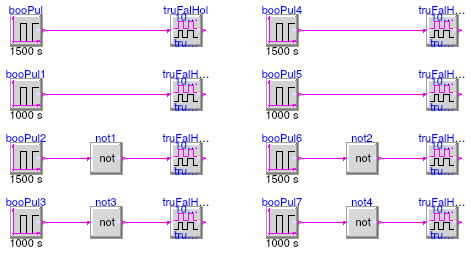
Validation model for the TrueFalseHold block
Information
Validation test for the block Buildings.Controls.OBC.CDL.Logical.TrueFalseHold.
The validation uses different instances to validate different hold trueHoldDurations, different lengths of the input pulse, and different initial values for the input signal.
Modelica definition
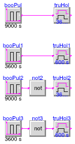
 Buildings.Controls.OBC.CDL.Logical.Validation.TrueHoldWithReset
Validation model for the TrueHoldWithReset block
Information
Validation test for the block Buildings.Controls.OBC.CDL.Logical.TrueHoldWithReset.
The validation uses different instances to validate different hold durations, different lengths of the input pulse, and different initial values for the input signal.
Modelica definition
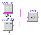
 Buildings.Controls.OBC.CDL.Logical.Validation.Xor
Validation model for the Xor block
Information
Validation test for the block Buildings.Controls.OBC.CDL.Logical.Xor.
Modelica definition
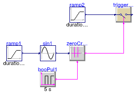
 Buildings.Controls.OBC.CDL.Logical.Validation.ZeroCrossing
Validation model for the zero crossing block
Information
Validation test for the block Buildings.Controls.OBC.CDL.Logical.ZeroCrossing.
