Subsequences for economizer control
Information
This package contains subsequences for single zone VAV AHU economizer control.
Package Content
| Name |
Description |
 Enable Enable
|
Single zone VAV AHU economizer enable/disable switch |
 Limits Limits
|
Single zone VAV AHU minimum outdoor air control - damper position limits |
 Modulation Modulation
|
Outdoor and return air damper position modulation sequence for single zone VAV AHU |
 Validation Validation
|
Collection of validation models |
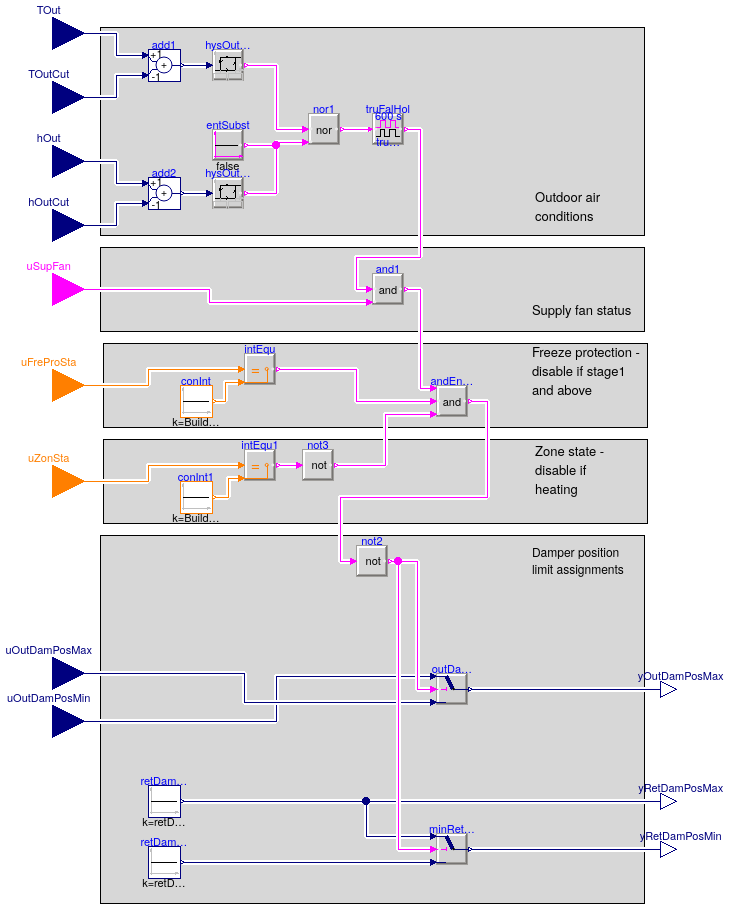
Single zone VAV AHU economizer enable/disable switch
Information
This is a single zone VAV AHU economizer enable/disable sequence
based on ASHRAE G36 PART5.5 and PART5.A.17. Additional
conditions included in the sequence are:
The economizer is disabled whenever the outdoor air conditions
exceed the economizer high limit setpoint.
This sequence allows for all device types listed in
ASHRAE 90.1-2013 and Title 24-2013.
In addition, the economizer is disabled without a delay whenever any of the
following is true:
- supply fan is off,
-
zone state is
heating,
-
freeze protection stage is not
0.
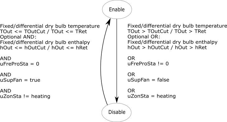
The following state machine chart illustrates the transitions between enabling and disabling:
Parameters
| Type | Name | Default | Description |
|---|
| Conditional |
| Boolean | use_enthalpy | true | Set to true to evaluate outdoor air (OA) enthalpy in addition to temperature |
| Advanced |
| Hysteresis |
| TemperatureDifference | delTOutHis | 1 | Delta between the temperature hysteresis high and low limit [K] |
| SpecificEnergy | delEntHis | 1000 | Delta between the enthalpy hysteresis high and low limits [J/kg] |
| Commissioning |
| Physical damper position limits |
| Real | retDamPhyPosMax | 1 | Physically fixed maximum position of the return air damper [1] |
| Real | retDamPhyPosMin | 0 | Physically fixed minimum position of the return air damper [1] |
Connectors
| Type | Name | Description |
|---|
| input RealInput | TOut | Outdoor air temperature [K] |
| input RealInput | hOut | Outdoor air enthalpy [J/kg] |
| input RealInput | TOutCut | OA temperature high limit cutoff. For differential dry bulb temeprature condition use return air temperature measurement [K] |
| input RealInput | hOutCut | OA enthalpy high limit cutoff. For differential enthalpy use return air enthalpy measurement [J/kg] |
| input RealInput | uOutDamPosMin | Minimum outdoor air damper position, get from damper position limits sequence [1] |
| input RealInput | uOutDamPosMax | Maximum outdoor air damper position, get from damper position limits sequence [1] |
| input BooleanInput | uSupFan | Supply fan on/off status signal |
| input IntegerInput | uZonSta | Zone state status signal |
| input IntegerInput | uFreProSta | Freeze protection stage status signal |
| output RealOutput | yOutDamPosMax | Maximum outdoor air damper position [1] |
| output RealOutput | yRetDamPosMin | Minimum return air damper position [1] |
| output RealOutput | yRetDamPosMax | Maximum return air damper position [1] |
Modelica definition
block Enable
parameter Boolean use_enthalpy = true
;
parameter Modelica.SIunits.TemperatureDifference delTOutHis=1
;
parameter Modelica.SIunits.SpecificEnergy delEntHis=1000
;
parameter Real retDamPhyPosMax(
final min=0,
final max=1,
final unit="1") = 1
;
parameter Real retDamPhyPosMin(
final min=0,
final max=1,
final unit="1") = 0
;
Buildings.Controls.OBC.CDL.Interfaces.RealInput TOut(
final unit="K",
final quantity = "ThermodynamicTemperature")
;
Buildings.Controls.OBC.CDL.Interfaces.RealInput hOut(
final unit="J/kg",
final quantity="SpecificEnergy")
if use_enthalpy
;
Buildings.Controls.OBC.CDL.Interfaces.RealInput TOutCut(
final unit="K",
final quantity = "ThermodynamicTemperature")
;
Buildings.Controls.OBC.CDL.Interfaces.RealInput hOutCut(
final unit="J/kg",
final quantity="SpecificEnergy")
if use_enthalpy
;
Buildings.Controls.OBC.CDL.Interfaces.RealInput uOutDamPosMin(
final unit="1",
final min=0,
final max=1)
;
Buildings.Controls.OBC.CDL.Interfaces.RealInput uOutDamPosMax(
final unit="1",
final min=0,
final max=1)
;
Buildings.Controls.OBC.CDL.Interfaces.BooleanInput uSupFan
;
Buildings.Controls.OBC.CDL.Interfaces.IntegerInput uZonSta
;
Buildings.Controls.OBC.CDL.Interfaces.IntegerInput uFreProSta
;
Buildings.Controls.OBC.CDL.Interfaces.RealOutput yOutDamPosMax(
final min=0,
final max=1,
final unit="1")
;
Buildings.Controls.OBC.CDL.Interfaces.RealOutput yRetDamPosMin(
final min=retDamPhyPosMin,
final max=retDamPhyPosMax,
final unit="1")
;
Buildings.Controls.OBC.CDL.Interfaces.RealOutput yRetDamPosMax(
final min=retDamPhyPosMin,
final max=retDamPhyPosMax,
final unit="1")
;
Buildings.Controls.OBC.CDL.Logical.And3 andEnaDis
;
Buildings.Controls.OBC.CDL.Logical.TrueFalseHold truFalHol(
trueHoldDuration=600) ;
protected
final parameter Modelica.SIunits.Temperature TOutHigLimCutHig = 0
;
final parameter Real TOutHigLimCutLow = TOutHigLimCutHig - delTOutHis
;
final parameter Modelica.SIunits.SpecificEnergy hOutHigLimCutHig = 0
;
final parameter Real hOutHigLimCutLow = hOutHigLimCutHig - delEntHis
;
Buildings.Controls.OBC.CDL.Logical.Sources.Constant entSubst(
final k=false)
if not use_enthalpy
;
Buildings.Controls.OBC.CDL.Continuous.Sources.Constant retDamPhyPosMinSig(
final k=retDamPhyPosMin)
;
Buildings.Controls.OBC.CDL.Continuous.Sources.Constant retDamPhyPosMaxSig(
final k=retDamPhyPosMax)
;
Buildings.Controls.OBC.CDL.Continuous.Hysteresis hysOutTem(
final uHigh=TOutHigLimCutHig,
final uLow=TOutHigLimCutLow)
;
Buildings.Controls.OBC.CDL.Continuous.Hysteresis hysOutEnt(
final uLow=hOutHigLimCutLow,
final uHigh=hOutHigLimCutHig)
if use_enthalpy
;
Buildings.Controls.OBC.CDL.Continuous.Add add2(
final k2=-1)
if use_enthalpy
;
Buildings.Controls.OBC.CDL.Continuous.Add add1(
final k2=-1)
;
Buildings.Controls.OBC.CDL.Logical.Switch outDamSwitch ;
Buildings.Controls.OBC.CDL.Logical.Switch minRetDamSwitch
;
Buildings.Controls.OBC.CDL.Logical.Nor nor1 ;
Buildings.Controls.OBC.CDL.Logical.Not not2 ;
Buildings.Controls.OBC.CDL.Logical.And and1 ;
Buildings.Controls.OBC.CDL.Integers.Sources.Constant conInt(
final k=Buildings.Controls.OBC.ASHRAE.G36_PR1.Types.FreezeProtectionStages.stage0);
Buildings.Controls.OBC.CDL.Integers.Equal intEqu
;
Buildings.Controls.OBC.CDL.Integers.Sources.Constant conInt1(
final k=Buildings.Controls.OBC.ASHRAE.G36_PR1.Types.ZoneStates.heating);
Buildings.Controls.OBC.CDL.Integers.Equal intEqu1
;
Buildings.Controls.OBC.CDL.Logical.Not not3 ;
equation
connect(outDamSwitch.y, yOutDamPosMax);
connect(TOut, add1.u1);
connect(TOutCut, add1.u2);
connect(add1.y, hysOutTem.u);
connect(hOut, add2.u1);
connect(hOutCut, add2.u2);
connect(add2.y, hysOutEnt.u);
connect(hysOutTem.y, nor1.u1);
connect(hysOutEnt.y, nor1.u2);
connect(entSubst.y, nor1.u2);
connect(uOutDamPosMin, outDamSwitch.u1);
connect(uOutDamPosMax, outDamSwitch.u3);
connect(nor1.y, truFalHol.u);
connect(andEnaDis.y, not2.u);
connect(minRetDamSwitch.y, yRetDamPosMin);
connect(truFalHol.y, and1.u1);
connect(and1.y, andEnaDis.u1);
connect(uSupFan, and1.u2);
connect(retDamPhyPosMaxSig.y, minRetDamSwitch.u1);
connect(retDamPhyPosMinSig.y, minRetDamSwitch.u3);
connect(retDamPhyPosMaxSig.y, yRetDamPosMax);
connect(not2.y, minRetDamSwitch.u2);
connect(not2.y, outDamSwitch.u2);
connect(conInt.y,intEqu. u2);
connect(conInt1.y,intEqu1. u2);
connect(intEqu1.y,not3. u);
connect(uZonSta, intEqu1.u1);
connect(uFreProSta, intEqu.u1);
connect(intEqu.y, andEnaDis.u2);
connect(not3.y, andEnaDis.u3);
end Enable;
Single zone VAV AHU minimum outdoor air control - damper position limits
Information
This block implements the single zone VAV AHU minimum outdoor air control with a single
common damper for minimum outdoor air and economizer functions based on outdoor airflow
setpoint (VOutMinSet_flow) and supply fan speed (uSupFanSpe),
designed in line with ASHRAE Guidline 36, PART5.P.4.d.
The controller is enabled when the supply fan is proven on (uSupFan=true),
the AHU operation mode uOpeMod is Occupied, and Freeze protection stage
uFreProSta is 1 or smaller. Otherwise the damper position limits are set to
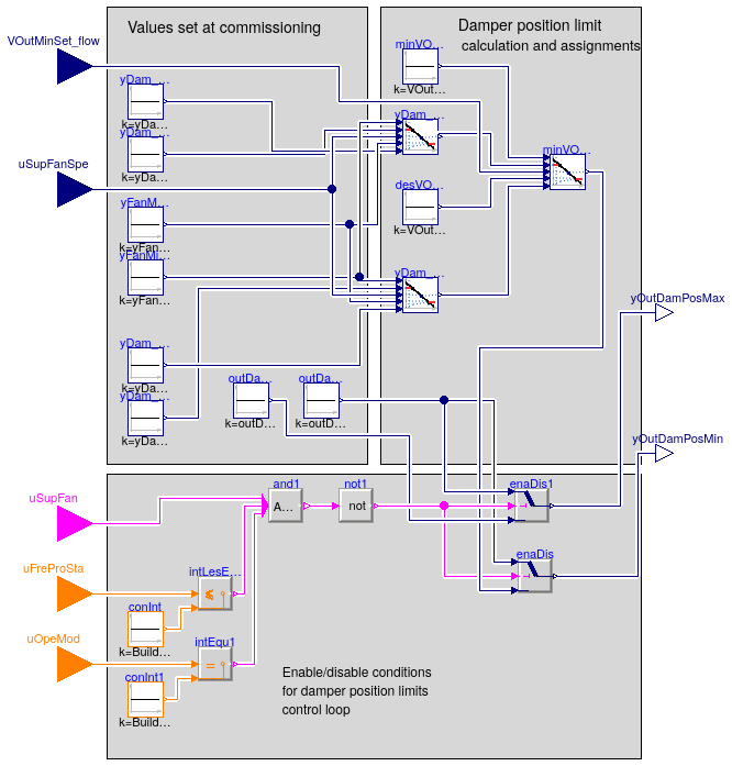
their corresponding maximum and minimum physical or at commissioning fixed limits, as illustrated below:

If limit modulation is enabled, the outdoor air damper position yOutDamPosMin is computed as
follows:
-
Calculate outdoor air damper position
yDam_VOutMin_curSpe
which ensures minimum outdoor airflow rate VOutMin_flow
at current supply fan speed uSupFanSpe as a linear
interpolation between the following values set at commissioning:
- minimum damper position at minimum fan speed for minimum outdoor airflow
yDam_VOutMin_minSpe and
-
minimum damper position at maximum fan speed for minimum outdoor airflow
yDam_VOutMin_maxSpe.
-
Calculate outdoor air damper position
yDam_VOutDes_curSpe
which ensures design outdoor airflow rate VOutDes_flow at
current supply fan speed uSupFanSpe, as a linear
interpolation between the following values set at commissioning:
-
minimum damper position at minimum fan speed for design outdoor airflow
yDam_VOutDes_minSpe and
-
minimum damper position at maximum fan speed for design outdoor airflow
yDam_VOutDes_maxSpe.
-
Calculate outdoor air damper position
yOutDamPosMin
which ensures outdoor airflow setpoint VOutMinSet_flow
at current supply fan speed uSupFanSpe as a linear interpolation
between yDam_VOutMin_curSpe and yDam_VOutDes_curSpe, proportional to ratios of
VOutMinSet_flow to VOutDes_flow and VOutMin_flow.
The chart below illustrates the OA damper position limit calculation:

Parameters
| Type | Name | Default | Description |
|---|
| Commissioning |
| Damper position limits |
| Real | yFanMin | 0.1 | Minimum supply fan operation speed [1] |
| Real | yFanMax | 1 | Maximum supply fan operation speed [1] |
| Real | yDam_VOutMin_minSpe | 0.4 | OA damper position to supply minimum outdoor airflow at minimum fan speed [1] |
| Real | yDam_VOutMin_maxSpe | 0.3 | OA damper position to supply minimum outdoor airflow at maximum fan speed [1] |
| Real | yDam_VOutDes_minSpe | 0.9 | OA damper position to supply design outdoor airflow at minimum fan speed [1] |
| Real | yDam_VOutDes_maxSpe | 0.8 | OA damper position to supply design outdoor airflow at maximum fan speed [1] |
| VolumeFlowRate | VOutMin_flow | | Calculated minimum outdoor airflow rate [m3/s] |
| VolumeFlowRate | VOutDes_flow | | Calculated design outdoor airflow rate [m3/s] |
| Physical damper position limits |
| Real | outDamPhyPosMax | 1 | Physically fixed maximum position of the outdoor air (OA) damper [1] |
| Real | outDamPhyPosMin | 0 | Physically fixed minimum position of the outdoor air damper [1] |
Connectors
| Type | Name | Description |
|---|
| input RealInput | uSupFanSpe | Supply fan speed [1] |
| input RealInput | VOutMinSet_flow | Minimum outdoor airflow setpoint [m3/s] |
| input IntegerInput | uOpeMod | AHU operation mode status signal |
| input IntegerInput | uFreProSta | Freeze protection status signal |
| input BooleanInput | uSupFan | Supply fan status signal |
| output RealOutput | yOutDamPosMin | Minimum outdoor air damper position limit [1] |
| output RealOutput | yOutDamPosMax | Maximum outdoor air damper position limit [1] |
Modelica definition
block Limits
parameter Real yFanMin(
final min=0,
final max=1,
final unit="1") = 0.1 ;
parameter Real yFanMax(
final min=0,
final max=1,
final unit="1") = 1 ;
parameter Real yDam_VOutMin_minSpe(
final min=outDamPhyPosMin,
final max=outDamPhyPosMax,
final unit="1") = 0.4
;
parameter Real yDam_VOutMin_maxSpe(
final min=outDamPhyPosMin,
final max=outDamPhyPosMax,
final unit="1") = 0.3
;
parameter Real yDam_VOutDes_minSpe(
final min=yDam_VOutMin_minSpe,
final max=outDamPhyPosMax,
final unit="1") = 0.9
;
parameter Real yDam_VOutDes_maxSpe(
final min=yDam_VOutMin_maxSpe,
final max=outDamPhyPosMax,
final unit="1") = 0.8
;
parameter Modelica.SIunits.VolumeFlowRate VOutMin_flow
;
parameter Modelica.SIunits.VolumeFlowRate VOutDes_flow
;
parameter Real outDamPhyPosMax(
final min=0,
final max=1,
final unit="1") = 1
;
parameter Real outDamPhyPosMin(
final min=0,
final max=1,
final unit="1") = 0
;
Buildings.Controls.OBC.CDL.Interfaces.RealInput uSupFanSpe(
final min=0,
final max=1,
final unit="1")
;
Buildings.Controls.OBC.CDL.Interfaces.RealInput VOutMinSet_flow(
final unit="m3/s",
final quantity="VolumeFlowRate",
final min=VOutMin_flow,
final max=VOutDes_flow)
;
Buildings.Controls.OBC.CDL.Interfaces.IntegerInput uOpeMod
;
Buildings.Controls.OBC.CDL.Interfaces.IntegerInput uFreProSta
;
Buildings.Controls.OBC.CDL.Interfaces.BooleanInput uSupFan
;
Buildings.Controls.OBC.CDL.Interfaces.RealOutput yOutDamPosMin(
final min=outDamPhyPosMin,
final max=outDamPhyPosMax,
final unit="1")
;
Buildings.Controls.OBC.CDL.Interfaces.RealOutput yOutDamPosMax(
final min=outDamPhyPosMin,
final max=outDamPhyPosMax,
final unit="1")
;
protected
Buildings.Controls.OBC.CDL.Continuous.Sources.Constant yFanMinSig(
final k=yFanMin) ;
Buildings.Controls.OBC.CDL.Continuous.Sources.Constant outDamPhyPosMinSig(
final k=outDamPhyPosMin)
;
Buildings.Controls.OBC.CDL.Continuous.Sources.Constant outDamPhyPosMaxSig(
final k=outDamPhyPosMax)
;
Buildings.Controls.OBC.CDL.Continuous.Sources.Constant yFanMaxSig(
final k=yFanMax) ;
Buildings.Controls.OBC.CDL.Continuous.Sources.Constant yDam_VOutMin_minSpeSig(
final k=yDam_VOutMin_minSpe)
;
Buildings.Controls.OBC.CDL.Continuous.Sources.Constant yDam_VOutDes_minSpeSig(
final k=yDam_VOutDes_minSpe)
;
Buildings.Controls.OBC.CDL.Continuous.Sources.Constant yDam_VOutMin_maxSpeSig(
final k=yDam_VOutMin_maxSpe)
;
Buildings.Controls.OBC.CDL.Continuous.Sources.Constant yDam_VOutDes_maxSpeSig(
final k=yDam_VOutDes_maxSpe)
;
Buildings.Controls.OBC.CDL.Continuous.Sources.Constant minVOutSig(
final k=VOutMin_flow) ;
Buildings.Controls.OBC.CDL.Continuous.Sources.Constant desVOutSig(
final k=VOutDes_flow) ;
Buildings.Controls.OBC.CDL.Continuous.Line yDam_VOutMin_curSpe(
final limitBelow=true,
final limitAbove=true)
;
Buildings.Controls.OBC.CDL.Continuous.Line yDam_VOutDes_curSpe(
final limitBelow=true,
final limitAbove=true)
;
Buildings.Controls.OBC.CDL.Continuous.Line minVOutSetCurFanSpePos(
final limitBelow=true,
final limitAbove=true)
;
Buildings.Controls.OBC.CDL.Logical.Switch enaDis
;
Buildings.Controls.OBC.CDL.Logical.MultiAnd and1(
final nu=3) ;
Buildings.Controls.OBC.CDL.Logical.Not not1 ;
Buildings.Controls.OBC.CDL.Logical.Switch enaDis1
;
Buildings.Controls.OBC.CDL.Integers.Sources.Constant conInt(
final k=Buildings.Controls.OBC.ASHRAE.G36_PR1.Types.FreezeProtectionStages.stage1)
;
Buildings.Controls.OBC.CDL.Integers.LessEqual intLesEqu
;
Buildings.Controls.OBC.CDL.Integers.Sources.Constant conInt1(
final k=Buildings.Controls.OBC.ASHRAE.G36_PR1.Types.OperationModes.occupied)
;
Buildings.Controls.OBC.CDL.Integers.Equal intEqu1 ;
equation
connect(minVOutSig.y, minVOutSetCurFanSpePos.x1);
connect(desVOutSig.y, minVOutSetCurFanSpePos.x2);
connect(yDam_VOutMin_curSpe.y, minVOutSetCurFanSpePos.f1);
connect(yDam_VOutDes_curSpe.y, minVOutSetCurFanSpePos.f2);
connect(enaDis.y, yOutDamPosMin);
connect(yDam_VOutDes_minSpeSig.y, yDam_VOutDes_curSpe.f1);
connect(yDam_VOutDes_maxSpeSig.y, yDam_VOutDes_curSpe.f2);
connect(yDam_VOutMin_minSpeSig.y, yDam_VOutMin_curSpe.f1);
connect(yDam_VOutMin_maxSpeSig.y, yDam_VOutMin_curSpe.f2);
connect(uSupFanSpe, yDam_VOutMin_curSpe.u);
connect(yFanMaxSig.y, yDam_VOutMin_curSpe.x2);
connect(yFanMinSig.y, yDam_VOutMin_curSpe.x1);
connect(yFanMinSig.y, yDam_VOutDes_curSpe.x1);
connect(yFanMaxSig.y, yDam_VOutDes_curSpe.x2);
connect(VOutMinSet_flow, minVOutSetCurFanSpePos.u);
connect(uSupFanSpe, yDam_VOutDes_curSpe.u);
connect(and1.y,not1. u);
connect(not1.y, enaDis.u2);
connect(outDamPhyPosMinSig.y, enaDis.u1);
connect(minVOutSetCurFanSpePos.y, enaDis.u3);
connect(outDamPhyPosMinSig.y, enaDis1.u1);
connect(outDamPhyPosMaxSig.y, enaDis1.u3);
connect(enaDis1.y, yOutDamPosMax);
connect(not1.y, enaDis1.u2);
connect(uSupFan, and1.u[1]);
connect(uOpeMod, intEqu1.u1);
connect(conInt1.y, intEqu1.u2);
connect(intLesEqu.y, and1.u[2]);
connect(intEqu1.y, and1.u[3]);
connect(intLesEqu.u2, conInt.y);
connect(uFreProSta, intLesEqu.u1);
end Limits;
Outdoor and return air damper position modulation sequence for single zone VAV AHU
Information
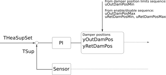
This is a single zone VAV AHU economizer modulation block. It calculates
the outdoor and return air damper positions based on the single zone VAV AHU
supply air temperature control loop signal. Economizer dampers are modulated
based on the calculated heating supply air temperature setpoint.
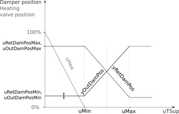
The implementation is in line with ASHRAE
Guidline 36 (G36), PART5.P.3.b. Damper positions are linearly mapped to
the supply air control loop signal. This is a final sequence in the
composite single zone VAV AHU economizer control sequence. Damper position
limits, which are the inputs to the sequence, are the outputs of
Buildings.Controls.OBC.ASHRAE.G36_PR1.AHUs.SingleZone.VAV.Economizers.Subsequences.Limits and
Buildings.Controls.OBC.ASHRAE.G36_PR1.AHUs.SingleZone.VAV.Economizers.Subsequences.Enable
sequences.
When the economizer is enabled, the PI controller modulates the damper
positions. Return and outdoor damper are not interlocked. When the economizer is disabled,
the damper positions are set to the minimum outdoor air damper position limits.
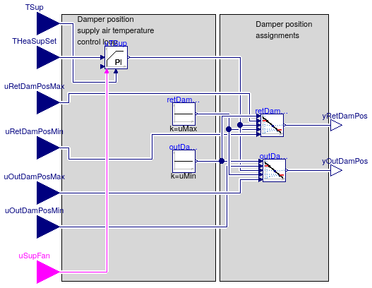
The control charts below show the input-output structure and an economizer damper
modulation sequence assuming a well configured controller. Control diagram:
Single zone AHU economizer modulation control chart:
Parameters
| Type | Name | Default | Description |
|---|
| SimpleController | controllerType | Buildings.Controls.OBC.CDL.T... | Type of controller |
| Real | k | 1 | Gain of controller [1/K] |
| Time | Ti | 300 | Time constant of modulation controller integrator block [s] |
| Time | Td | 0.1 | Time constant of derivative block for cooling control loop signal [s] |
| Real | uMin | 0 | Lower limit of controller output uTSup at which the dampers are at their limits |
| Real | uMax | 1 | Upper limit of controller output uTSup at which the dampers are at their limits |
Connectors
| Type | Name | Description |
|---|
| input RealInput | TSup | Measured supply air temperature [K] |
| input RealInput | THeaSupSet | Supply air temperature heating setpoint [K] |
| input BooleanInput | uSupFan | Supply fan status |
| input RealInput | uOutDamPosMin | Minimum economizer damper position limit as returned by the damper position limits sequence [1] |
| input RealInput | uOutDamPosMax | Maximum economizer damper position limit as returned by the economizer enable-disable sequence.
If the economizer is disabled, this value equals uOutDamPosMin [1] |
| input RealInput | uRetDamPosMin | Minimum return air damper position limit as returned by the economizer enable-disable sequence [1] |
| input RealInput | uRetDamPosMax | Maximum return air damper position limit as returned by the economizer enable-disable sequence [1] |
| output RealOutput | yOutDamPos | Economizer damper position [1] |
| output RealOutput | yRetDamPos | Return air damper position [1] |
Modelica definition
block Modulation
parameter Buildings.Controls.OBC.CDL.Types.SimpleController controllerType=
Buildings.Controls.OBC.CDL.Types.SimpleController.PI
;
parameter Real k(
final unit="1/K") = 1 ;
parameter Modelica.SIunits.Time Ti=300
;
parameter Modelica.SIunits.Time Td=0.1
;
parameter Real uMin=0
;
parameter Real uMax=1
;
Buildings.Controls.OBC.CDL.Interfaces.RealInput TSup(
final unit="K",
final quantity = "ThermodynamicTemperature")
;
Buildings.Controls.OBC.CDL.Interfaces.RealInput THeaSupSet(
final unit="K",
final quantity = "ThermodynamicTemperature") ;
Buildings.Controls.OBC.CDL.Interfaces.BooleanInput uSupFan ;
Buildings.Controls.OBC.CDL.Interfaces.RealInput uOutDamPosMin(
final min=0,
final max=1,
final unit="1")
;
Buildings.Controls.OBC.CDL.Interfaces.RealInput uOutDamPosMax(
final min=0,
final max=1,
final unit="1")
;
Buildings.Controls.OBC.CDL.Interfaces.RealInput uRetDamPosMin(
final min=0,
final max=1,
final unit="1")
;
Buildings.Controls.OBC.CDL.Interfaces.RealInput uRetDamPosMax(
final min=0,
final max=1,
final unit="1")
;
Buildings.Controls.OBC.CDL.Interfaces.RealOutput yOutDamPos(
final min=0,
final max=1,
final unit="1") ;
Buildings.Controls.OBC.CDL.Interfaces.RealOutput yRetDamPos(
final min=0,
final max=1,
final unit="1") ;
Buildings.Controls.OBC.CDL.Continuous.LimPID uTSup(
final controllerType=controllerType,
final k=k,
final Ti=Ti,
final Td=Td,
final yMax=uMax,
final yMin=uMin,
reset=Buildings.Controls.OBC.CDL.Types.Reset.Parameter)
;
protected
Buildings.Controls.OBC.CDL.Continuous.Sources.Constant outDamMinLimSig(
final k=uMin) ;
Buildings.Controls.OBC.CDL.Continuous.Sources.Constant retDamMaxLimSig(
final k=uMax) ;
Buildings.Controls.OBC.CDL.Continuous.Line outDamPos(
final limitBelow=true,
final limitAbove=true)
;
Buildings.Controls.OBC.CDL.Continuous.Line retDamPos(
final limitBelow=true,
final limitAbove=true)
;
equation
connect(TSup, uTSup.u_m);
connect(outDamPos.y, yOutDamPos);
connect(retDamPos.y, yRetDamPos);
connect(retDamMaxLimSig.y,retDamPos. x2);
connect(uTSup.y, retDamPos.u);
connect(uTSup.y, outDamPos.u);
connect(uRetDamPosMax,retDamPos. f1);
connect(uOutDamPosMin, outDamPos.f1);
connect(outDamMinLimSig.y, outDamPos.x1);
connect(THeaSupSet, uTSup.u_s);
connect(uRetDamPosMin,retDamPos. f2);
connect(uOutDamPosMax, outDamPos.f2);
connect(retDamMaxLimSig.y, outDamPos.x2);
connect(outDamMinLimSig.y, retDamPos.x1);
connect(uSupFan, uTSup.trigger);
end Modulation;
 Buildings.Controls.OBC.ASHRAE.G36_PR1.AHUs.SingleZone.VAV.Economizers.Subsequences.Enable
 Buildings.Controls.OBC.ASHRAE.G36_PR1.AHUs.SingleZone.VAV.Economizers.Subsequences.Limits
 Buildings.Controls.OBC.ASHRAE.G36_PR1.AHUs.SingleZone.VAV.Economizers.Subsequences.Modulation