Buildings.Fluid.FixedResistances
Package with models for fixed flow resistances
Information
This package contains component models for fixed flow resistances. By fixed flow resistance, we mean resistances that do not change the flow coefficient
k = m ⁄ √ΔP.
For models of valves and air dampers, see Buildings.Fluid.Actuators. For models of flow resistances as part of the building constructions, see Buildings.Airflow.Multizone.
The model Buildings.Fluid.FixedResistances.PressureDrop is a fixed flow resistance that takes as parameter a nominal flow rate and a nominal pressure drop. The actual resistance is scaled using the above equation.
The model Buildings.Fluid.FixedResistances.HydraulicDiameter is a fixed flow resistance that takes as parameter a nominal flow rate and a hydraulic diameter. The actual resistance is scaled using the above equation.
The model Buildings.Fluid.FixedResistances.LosslessPipe is an ideal pipe segment with no pressure drop. It is primarily used in models in which the above pressure drop model need to be replaced by a model with no pressure drop.
The model Buildings.Fluid.FixedResistances.Junction can be used to model flow splitters or flow merges.
Extends from Modelica.Icons.VariantsPackage (Icon for package containing variants).
Package Content
| Name | Description |
|---|---|
| Fixed flow resistance with hydraulic diameter and m_flow as parameter | |
| Flow splitter with fixed resistance at each port | |
| Pipe with no flow friction and no heat transfer | |
| Pipe with finite volume discretization along flow path | |
| Fixed flow resistance with dp and m_flow as parameter | |
| Collection of models that illustrate model use and test models | |
| Collection of validation models | |
 Buildings.Fluid.FixedResistances.HydraulicDiameter
Fixed flow resistance with hydraulic diameter and m_flow as parameter

Information
This is a model of a flow resistance with a fixed flow coefficient. The mass flow rate is computed as
ṁ = k √ΔP,
where
k is a constant and
ΔP is the pressure drop.
The constant k is equal to
k=m_flow_nominal/sqrt(dp_nominal),
where m_flow_nominal is a parameter.
Assumptions
In the region
abs(m_flow) < m_flow_turbulent,
the square root is replaced by a differentiable function
with finite slope.
The value of m_flow_turbulent is
computed as
m_flow_turbulent = eta_nominal*dh/4*π*ReC,
where
eta_nominal is the dynamic viscosity, obtained from
the medium model. The parameter
dh is the hydraulic diameter and
ReC=4000 is the critical Reynolds number, which both
can be set by the user.
Important parameters
By default, the pressure drop at nominal flow rate is computed as
dp_nominal = fac * dpStraightPipe_nominal,
where dpStraightPipe_nominal is a parameter that is automatically computed
based on the
nominal mass flow rate, hydraulic diameter, pipe roughness and medium properties.
The hydraulic diameter dh is by default
computed based on the flow velocity v_nominal and the nominal
mass flow rate m_flow_nominal. Hence, users should change the
default values of dh or v_nominal
if they are not applicable for their model.
The factor fac takes into account additional resistances such as
for bends. The default value of 2 can be changed by the user.
The parameter from_dp is used to determine
whether the mass flow rate is computed as a function of the
pressure drop (if from_dp=true), or vice versa.
This setting can affect the size of the nonlinear system of equations.
If the parameter linearized is set to true,
then the pressure drop is computed as a linear function of the
mass flow rate.
Setting allowFlowReversal=false can lead to simpler
equations. However, this should only be set to false
if one can guarantee that the flow never reverses its direction.
This can be difficult to guarantee, as pressure imbalance after
the initialization, or due to medium expansion and contraction,
can lead to reverse flow.
If the parameter
show_T is set to true,
then the model will compute the
temperature at its ports. Note that this can lead to state events
when the mass flow rate approaches zero,
which can increase computing time.
Notes
For more detailed models that compute the actual flow friction,
models from the package
Modelica.Fluid
can be used and combined with models from the
Buildings library.
For a model that uses dp_nominal as a parameter rather than
geoemetric data, use
Buildings.Fluid.FixedResistances.PressureDrop.
Implementation
The pressure drop is computed by calling a function in the package Buildings.Fluid.BaseClasses.FlowModels, This package contains regularized implementations of the equation
m = sign(Δp) k √ Δp
and its inverse function.
To decouple the energy equation from the mass equations, the pressure drop is a function of the mass flow rate, and not the volume flow rate. This leads to simpler equations.
Extends from Buildings.Fluid.FixedResistances.PressureDrop (Fixed flow resistance with dp and m_flow as parameter).
Parameters
| Type | Name | Default | Description |
|---|---|---|---|
| replaceable package Medium | PartialMedium | Medium in the component | |
| Length | dh | sqrt(4*m_flow_nominal/rho_de... | Hydraulic diameter (assuming a round cross section area) [m] |
| Length | length | Length of the pipe [m] | |
| Real | ReC | 4000 | Reynolds number where transition to turbulent starts |
| Length | roughness | 2.5e-5 | Absolute roughness of pipe, with a default for a smooth steel pipe (dummy if use_roughness = false) [m] |
| Real | fac | 2 | Factor to take into account resistance of bends etc., fac=dp_nominal/dpStraightPipe_nominal |
| Nominal condition | |||
| MassFlowRate | m_flow_nominal | Nominal mass flow rate [kg/s] | |
| PressureDifference | dp_nominal | fac*dpStraightPipe_nominal | Pressure drop at nominal mass flow rate [Pa] |
| Velocity | v_nominal | if rho_default < 500 then 1.... | Velocity at m_flow_nominal (used to compute default value for hydraulic diameter dh) [m/s] |
| Transition to laminar | |||
| Real | deltaM | eta_default*dh/4*Modelica.Co... | Fraction of nominal mass flow rate where transition to turbulent occurs |
| Assumptions | |||
| Boolean | allowFlowReversal | true | = false to simplify equations, assuming, but not enforcing, no flow reversal |
| Advanced | |||
| Diagnostics | |||
| Boolean | show_T | false | = true, if actual temperature at port is computed |
| Boolean | from_dp | false | = true, use m_flow = f(dp) else dp = f(m_flow) |
| Boolean | homotopyInitialization | true | = true, use homotopy method |
| Boolean | linearized | false | = true, use linear relation between m_flow and dp for any flow rate |
Connectors
| Type | Name | Description |
|---|---|---|
| FluidPort_a | port_a | Fluid connector a (positive design flow direction is from port_a to port_b) |
| FluidPort_b | port_b | Fluid connector b (positive design flow direction is from port_a to port_b) |
Modelica definition
 Buildings.Fluid.FixedResistances.Junction
Flow splitter with fixed resistance at each port
Information
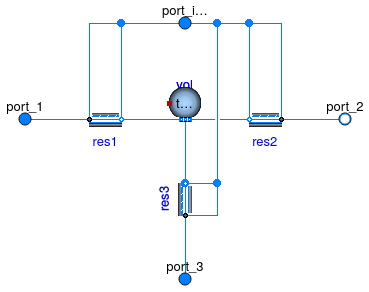
Model of a flow junction with an optional fixed resistance in each flow leg and an optional mixing volume at the junction.
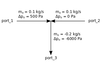
The pressure drop is implemented using the model Buildings.Fluid.FixedResistances.PressureDrop. If its nominal pressure drop is set to zero, then the pressure drop model will be removed. For example, the pressure drop declaration
  m_flow_nominal={ 0.1, 0.1,  -0.2},
  dp_nominal =   {500,    0, -6000}
would model a flow mixer that has the nominal flow rates and associated pressure drops
as shown in the figure below. Note that port_3 is set to negative values.
The negative values indicate that at the nominal conditions, fluid is leaving the component.
If
energyDynamics <> Modelica.Fluid.Types.Dynamics.SteadyState,
then at the flow junction, a fluid volume is modeled.
The fluid volume is implemented using the model
Buildings.Fluid.Delays.DelayFirstOrder.
The fluid volume has the size
V = sum(abs(m_flow_nominal[:])/3)*tau/rho_nominal
where tau is a parameter and rho_nominal is the density
of the medium in the volume at nominal condition.
Setting energyDynamics=Modelica.Fluid.Types.Dynamics.FixedInitial
can help reducing the size of the nonlinear
system of equations.
Extends from Buildings.Fluid.BaseClasses.PartialThreeWayResistance (Flow splitter with partial resistance model at each port).
Parameters
| Type | Name | Default | Description |
|---|---|---|---|
| replaceable package Medium | PartialMedium | Medium in the component | |
| Nominal condition | |||
| MassFlowRate | m_flow_nominal[3] | Mass flow rate. Set negative at outflowing ports. [kg/s] | |
| Pressure | dp_nominal[3] | Pressure drop at nominal mass flow rate, set to zero or negative number at outflowing ports. [Pa] | |
| Transition to laminar | |||
| Real | deltaM | 0.3 | Fraction of nominal mass flow rate where transition to turbulent occurs |
| Dynamics | |||
| Equations | |||
| Dynamics | energyDynamics | Modelica.Fluid.Types.Dynamic... | Type of energy balance: dynamic (3 initialization options) or steady state |
| Dynamics | massDynamics | energyDynamics | Type of mass balance: dynamic (3 initialization options) or steady state |
| MassFlowRate | mDyn_flow_nominal | sum(abs(m_flow_nominal[:])/3) | Nominal mass flow rate for dynamic momentum and energy balance [kg/s] |
| Nominal condition | |||
| Time | tau | 10 | Time constant at nominal flow for dynamic energy and momentum balance [s] |
| Initialization | |||
| AbsolutePressure | p_start | Medium.p_default | Start value of pressure [Pa] |
| Temperature | T_start | Medium.T_default | Start value of temperature [K] |
| MassFraction | X_start[Medium.nX] | Medium.X_default | Start value of mass fractions m_i/m [kg/kg] |
| ExtraProperty | C_start[Medium.nC] | fill(0, Medium.nC) | Start value of trace substances |
| ExtraProperty | C_nominal[Medium.nC] | fill(1E-2, Medium.nC) | Nominal value of trace substances. (Set to typical order of magnitude.) |
| Advanced | |||
| Boolean | from_dp | true | = true, use m_flow = f(dp) else dp = f(m_flow) |
| PortFlowDirection | portFlowDirection_1 | Modelica.Fluid.Types.PortFlo... | Flow direction for port_1 |
| PortFlowDirection | portFlowDirection_2 | Modelica.Fluid.Types.PortFlo... | Flow direction for port_2 |
| PortFlowDirection | portFlowDirection_3 | Modelica.Fluid.Types.PortFlo... | Flow direction for port_3 |
| Boolean | linearized | false | = true, use linear relation between m_flow and dp for any flow rate |
| Boolean | homotopyInitialization | true | = true, use homotopy method |
Connectors
| Type | Name | Description |
|---|---|---|
| FluidPort_a | port_1 | First port, typically inlet |
| FluidPort_b | port_2 | Second port, typically outlet |
| FluidPort_a | port_3 | Third port, can be either inlet or outlet |
Modelica definition
 Buildings.Fluid.FixedResistances.LosslessPipe
Pipe with no flow friction and no heat transfer

Information
Model of a pipe with no flow resistance, no heat loss and no transport delay.
This model can be used to replace a replaceable pipe model
in flow legs in which no friction should be modeled.
This is for example done in the outlet port of the
base class for three way valves,
Buildings.Fluid.Actuators.BaseClasses.PartialThreeWayValve.
Extends from Buildings.Fluid.Interfaces.PartialTwoPortInterface (Partial model transporting fluid between two ports without storing mass or energy).
Parameters
| Type | Name | Default | Description |
|---|---|---|---|
| replaceable package Medium | PartialMedium | Medium in the component | |
| Nominal condition | |||
| MassFlowRate | m_flow_nominal | Nominal mass flow rate [kg/s] | |
| Assumptions | |||
| Boolean | allowFlowReversal | true | = false to simplify equations, assuming, but not enforcing, no flow reversal |
| Advanced | |||
| MassFlowRate | m_flow_small | 1E-4*abs(m_flow_nominal) | Small mass flow rate for regularization of zero flow [kg/s] |
| Diagnostics | |||
| Boolean | show_T | false | = true, if actual temperature at port is computed |
Connectors
| Type | Name | Description |
|---|---|---|
| FluidPort_a | port_a | Fluid connector a (positive design flow direction is from port_a to port_b) |
| FluidPort_b | port_b | Fluid connector b (positive design flow direction is from port_a to port_b) |
Modelica definition
 Buildings.Fluid.FixedResistances.Pipe
Pipe with finite volume discretization along flow path
Information
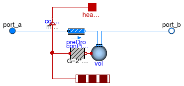
Model of a pipe with flow resistance and optional heat exchange with environment.
Heat loss calculation
There are two possible configurations:
-
If
useMultipleHeatPorts=false(default option), the pipe uses a single heat port for the heat exchange with the environment. Note that if the heat port is unconnected, then all volumes are still connected through the heat conduction elementsconPipWal. Therefore, they exchange a small amount of heat, which is not physical. To avoid this, setuseMultipleHeatPorts=true. -
If
useMultipleHeatPorts=true, then one heat port for each segment of the pipe is used for the heat exchange with the environment. If the heat port is unconnected, then the pipe has no heat loss.
Pressure drop calculation
The default value for the parameter diameter is computed such that the flow velocity
is equal to v_nominal=0.15 for a mass flow rate of m_flow_nominal.
Both parameters, diameter and v_nominal, can be overwritten
by the user.
The default value for dp_nominal is two times the pressure drop that the pipe
would have if it were straight with no fittings.
The factor of two that takes into account the pressure loss of fittings can be overwritten.
These fittings could also be explicitly modeled outside of this component using models from
the package
Modelica.Fluid.Fittings.
For mass flow rates other than m_flow_nominal, the model
Buildings.Fluid.FixedResistances.PressureDrop is used to
compute the pressure drop.
For a steady-state model of a flow resistance, use Buildings.Fluid.FixedResistances.PressureDrop instead of this model.
Extends from Buildings.Fluid.FixedResistances.BaseClasses.Pipe (Model of a pipe with finite volume discretization along the flow path).
Parameters
| Type | Name | Default | Description |
|---|---|---|---|
| replaceable package Medium | PartialMedium | Medium in the component | |
| Integer | nSeg | 10 | Number of volume segments |
| Length | thicknessIns | Thickness of insulation [m] | |
| ThermalConductivity | lambdaIns | Heat conductivity of insulation [W/(m.K)] | |
| Length | diameter | sqrt(4*m_flow_nominal/rho_de... | Pipe diameter (without insulation) [m] |
| Length | length | Length of the pipe [m] | |
| Velocity | v_nominal | 0.15 | Velocity at m_flow_nominal (used to compute default diameter) [m/s] |
| Length | roughness | 2.5e-5 | Absolute roughness of pipe, with a default for a smooth steel pipe (dummy if use_roughness = false) [m] |
| Boolean | useMultipleHeatPorts | false | = true to use one heat port for each segment of the pipe, false to use a single heat port for the entire pipe |
| Nominal condition | |||
| MassFlowRate | m_flow_nominal | Nominal mass flow rate [kg/s] | |
| PressureDifference | dp_nominal | 2*dpStraightPipe_nominal | Pressure difference [Pa] |
| Dynamics | |||
| Equations | |||
| Dynamics | energyDynamics | Modelica.Fluid.Types.Dynamic... | Type of energy balance: dynamic (3 initialization options) or steady state |
| Dynamics | massDynamics | energyDynamics | Type of mass balance: dynamic (3 initialization options) or steady state |
| Real | mSenFac | 1 | Factor for scaling the sensible thermal mass of the volume |
| Initialization | |||
| AbsolutePressure | p_start | Medium.p_default | Start value of pressure [Pa] |
| Temperature | T_start | Medium.T_default | Start value of temperature [K] |
| MassFraction | X_start[Medium.nX] | Medium.X_default | Start value of mass fractions m_i/m [kg/kg] |
| ExtraProperty | C_start[Medium.nC] | fill(0, Medium.nC) | Start value of trace substances |
| ExtraProperty | C_nominal[Medium.nC] | fill(1E-2, Medium.nC) | Nominal value of trace substances. (Set to typical order of magnitude.) |
| Assumptions | |||
| Boolean | allowFlowReversal | true | = false to simplify equations, assuming, but not enforcing, no flow reversal |
| Advanced | |||
| MassFlowRate | m_flow_small | 1E-4*abs(m_flow_nominal) | Small mass flow rate for regularization of zero flow [kg/s] |
| Boolean | homotopyInitialization | true | = true, use homotopy method |
| Flow resistance | |||
| Boolean | from_dp | false | = true, use m_flow = f(dp) else dp = f(m_flow) |
| Boolean | linearizeFlowResistance | false | = true, use linear relation between m_flow and dp for any flow rate |
| Real | deltaM | 0.1 | Fraction of nominal flow rate where flow transitions to laminar |
| Real | ReC | 4000 | Reynolds number where transition to turbulent starts |
Connectors
| Type | Name | Description |
|---|---|---|
| FluidPort_a | port_a | Fluid connector a (positive design flow direction is from port_a to port_b) |
| FluidPort_b | port_b | Fluid connector b (positive design flow direction is from port_a to port_b) |
| HeatPort_a | heatPort | Single heat port that connects to outside of pipe wall (default, enabled when useMultipleHeatPorts=false) |
| HeatPorts_a | heatPorts[nSeg] | Multiple heat ports that connect to outside of pipe wall (enabled if useMultipleHeatPorts=true) |
Modelica definition
 Buildings.Fluid.FixedResistances.PressureDrop
Fixed flow resistance with dp and m_flow as parameter

Information
Model of a flow resistance with a fixed flow coefficient. The mass flow rate is
ṁ = k √ΔP,
where
k is a constant and
ΔP is the pressure drop.
The constant k is equal to
k=m_flow_nominal/sqrt(dp_nominal),
where m_flow_nominal and dp_nominal
are parameters.
Assumptions
In the region
abs(m_flow) < m_flow_turbulent,
the square root is replaced by a differentiable function
with finite slope.
The value of m_flow_turbulent is
computed as
m_flow_turbulent = deltaM * abs(m_flow_nominal),
where deltaM=0.3 and
m_flow_nominal are parameters that can be set by the user.
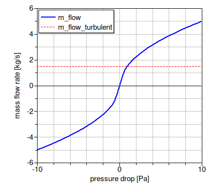
The figure below shows the pressure drop for the parameters
m_flow_nominal=5 kg/s,
dp_nominal=10 Pa and
deltaM=0.3.
Important parameters
The parameter from_dp is used to determine
whether the mass flow rate is computed as a function of the
pressure drop (if from_dp=true), or vice versa.
This setting can affect the size of the nonlinear system of equations.
If the parameter linearized is set to true,
then the pressure drop is computed as a linear function of the
mass flow rate.
Setting allowFlowReversal=false can lead to simpler
equations. However, this should only be set to false
if one can guarantee that the flow never reverses its direction.
This can be difficult to guarantee, as pressure imbalance after
the initialization, or due to medium expansion and contraction,
can lead to reverse flow.
If the parameter
show_T is set to true,
then the model will compute the
temperature at its ports. Note that this can lead to state events
when the mass flow rate approaches zero,
which can increase computing time.
Notes
For more detailed models that compute the actual flow friction,
models from the package
Modelica.Fluid
can be used and combined with models from the
Buildings library.
For a model that uses the hydraulic parameter and flow velocity at nominal conditions as a parameter, use Buildings.Fluid.FixedResistances.HydraulicDiameter.
Implementation
The pressure drop is computed by calling a function in the package Buildings.Fluid.BaseClasses.FlowModels, This package contains regularized implementations of the equation
m = sign(Δp) k √ Δp
and its inverse function.
To decouple the energy equation from the mass equations, the pressure drop is a function of the mass flow rate, and not the volume flow rate. This leads to simpler equations.
Extends from Buildings.Fluid.BaseClasses.PartialResistance (Partial model for a hydraulic resistance).
Parameters
| Type | Name | Default | Description |
|---|---|---|---|
| replaceable package Medium | PartialMedium | Medium in the component | |
| MassFlowRate | m_flow_turbulent | if computeFlowResistance the... | Turbulent flow if |m_flow| >= m_flow_turbulent [kg/s] |
| Nominal condition | |||
| MassFlowRate | m_flow_nominal | Nominal mass flow rate [kg/s] | |
| PressureDifference | dp_nominal | Pressure drop at nominal mass flow rate [Pa] | |
| Transition to laminar | |||
| Real | deltaM | 0.3 | Fraction of nominal mass flow rate where transition to turbulent occurs |
| Assumptions | |||
| Boolean | allowFlowReversal | true | = false to simplify equations, assuming, but not enforcing, no flow reversal |
| Advanced | |||
| Diagnostics | |||
| Boolean | show_T | false | = true, if actual temperature at port is computed |
| Boolean | from_dp | false | = true, use m_flow = f(dp) else dp = f(m_flow) |
| Boolean | homotopyInitialization | true | = true, use homotopy method |
| Boolean | linearized | false | = true, use linear relation between m_flow and dp for any flow rate |
Connectors
| Type | Name | Description |
|---|---|---|
| FluidPort_a | port_a | Fluid connector a (positive design flow direction is from port_a to port_b) |
| FluidPort_b | port_b | Fluid connector b (positive design flow direction is from port_a to port_b) |