Variable air volume flow system with terminal reheat and five thermal zones
Information
Extends from Modelica.Icons.ExamplesPackage (Icon for packages containing runnable examples).
Package Content
| Name |
Description |
 ASHRAE2006 ASHRAE2006
|
Variable air volume flow system with terminal reheat and five thermal zones |
| Guideline36
|
Variable air volume flow system with terminal reheat and five thermal zones |
 Controls Controls
|
Package with controller models |
| ThermalZones
|
Package with models for the thermal zones |
 BaseClasses BaseClasses
|
Package with base classes for Buildings.Examples.VAVReheat |
Variable air volume flow system with terminal reheat and five thermal zones
Information
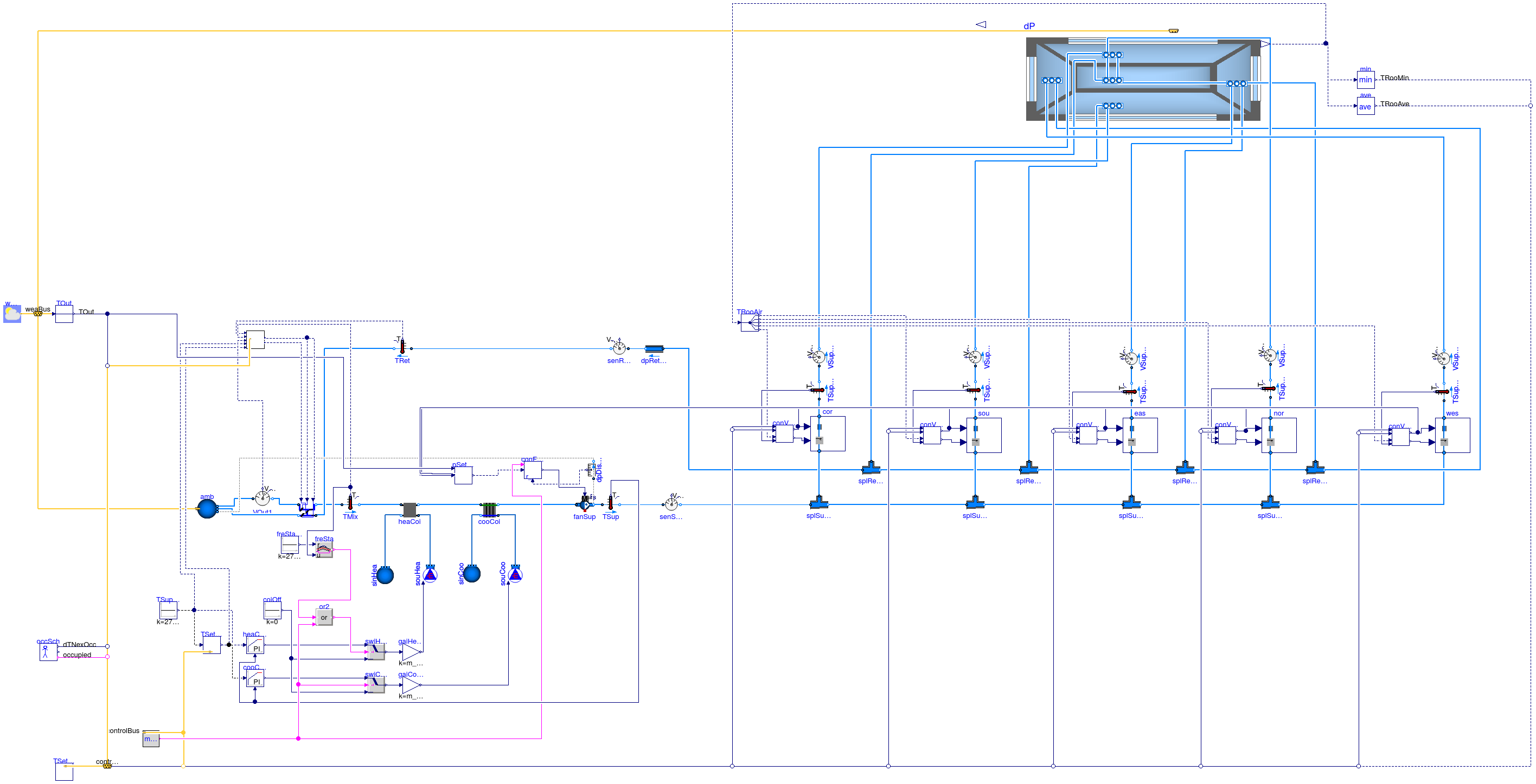
This model consist of an HVAC system, a building envelope model and a model
for air flow through building leakage and through open doors.
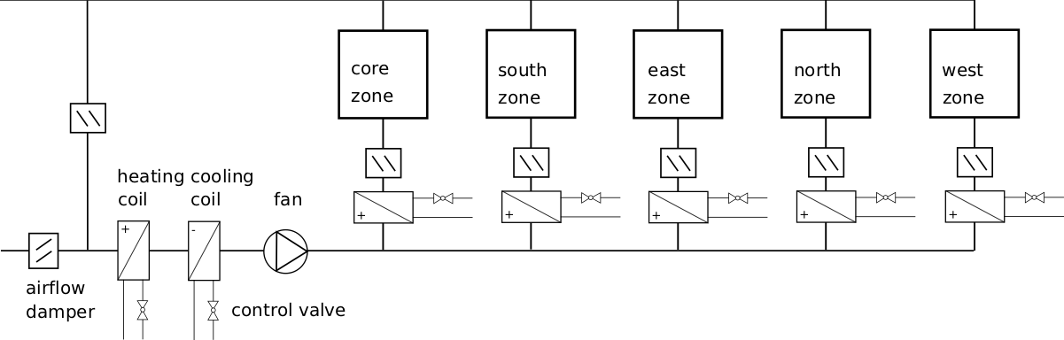
The HVAC system is a variable air volume (VAV) flow system with economizer
and a heating and cooling coil in the air handler unit. There is also a
reheat coil and an air damper in each of the five zone inlet branches.
The figure below shows the schematic diagram of the HVAC system
See the model
Buildings.Examples.VAVReheat.BaseClasses.PartialOpenLoop
for a description of the HVAC system and the building envelope.
The control is an implementation of the control sequence
VAV 2A2-21232 of the Sequences of Operation for
Common HVAC Systems (ASHRAE, 2006). In this control sequence, the
supply fan speed is regulated based on the duct static pressure.
The return fan controller tracks the supply fan air flow rate.
The duct static pressure is adjusted
so that at least one VAV damper is 90% open. The economizer dampers
are modulated to track the setpoint for the mixed air dry bulb temperature.
Priority is given to maintain a minimum outside air volume flow rate.
In each zone, the VAV damper is adjusted to meet the room temperature
setpoint for cooling, or fully opened during heating.
The room temperature setpoint for heating is tracked by varying
the water flow rate through the reheat coil. There is also a
finite state machine that transitions the mode of operation of
the HVAC system between the modes
occupied, unoccupied off, unoccupied night set back,
unoccupied warm-up and unoccupied pre-cool.
In the VAV model, all air flows are computed based on the
duct static pressure distribution and the performance curves of the fans.
Local loop control is implemented using proportional and proportional-integral
controllers, while the supervisory control is implemented
using a finite state machine.
A similar model but with a different control sequence can be found in
Buildings.Examples.VAVReheat.Guideline36.
References
ASHRAE.
Sequences of Operation for Common HVAC Systems.
ASHRAE, Atlanta, GA, 2006.
Extends from Modelica.Icons.Example (Icon for runnable examples), Buildings.Examples.VAVReheat.BaseClasses.PartialOpenLoop (Partial model of variable air volume flow system with terminal reheat and five thermal zones).
Parameters
| Type | Name | Default | Description |
|---|
| Volume | VRooCor | AFloCor*flo.hRoo | Room volume corridor [m3] |
| Volume | VRooSou | AFloSou*flo.hRoo | Room volume south [m3] |
| Volume | VRooNor | AFloNor*flo.hRoo | Room volume north [m3] |
| Volume | VRooEas | AFloEas*flo.hRoo | Room volume east [m3] |
| Volume | VRooWes | AFloWes*flo.hRoo | Room volume west [m3] |
| Area | AFloCor | flo.cor.AFlo | Floor area corridor [m2] |
| Area | AFloSou | flo.sou.AFlo | Floor area south [m2] |
| Area | AFloNor | flo.nor.AFlo | Floor area north [m2] |
| Area | AFloEas | flo.eas.AFlo | Floor area east [m2] |
| Area | AFloWes | flo.wes.AFlo | Floor area west [m2] |
| Area | AFlo[numZon] | {flo.cor.AFlo,flo.sou.AFlo,f... | Floor area of each zone [m2] |
| MassFlowRate | mCor_flow_nominal | 6*VRooCor*conv | Design mass flow rate core [kg/s] |
| MassFlowRate | mSou_flow_nominal | 6*VRooSou*conv | Design mass flow rate perimeter 1 [kg/s] |
| MassFlowRate | mEas_flow_nominal | 9*VRooEas*conv | Design mass flow rate perimeter 2 [kg/s] |
| MassFlowRate | mNor_flow_nominal | 6*VRooNor*conv | Design mass flow rate perimeter 3 [kg/s] |
| MassFlowRate | mWes_flow_nominal | 7*VRooWes*conv | Design mass flow rate perimeter 4 [kg/s] |
| MassFlowRate | m_flow_nominal | 0.7*(mCor_flow_nominal + mSo... | Nominal mass flow rate [kg/s] |
| Angle | lat | 41.98*3.14159/180 | Latitude [rad] |
| Temperature | THeaOn | 293.15 | Heating setpoint during on [K] |
| Temperature | THeaOff | 285.15 | Heating setpoint during off [K] |
| Temperature | TCooOn | 297.15 | Cooling setpoint during on [K] |
| Temperature | TCooOff | 303.15 | Cooling setpoint during off [K] |
| PressureDifference | dpBuiStaSet | 12 | Building static pressure [Pa] |
| Real | yFanMin | 0.1 | Minimum fan speed |
| Boolean | allowFlowReversal | true | = false to simplify equations, assuming, but not enforcing, no flow reversal |
| Boolean | use_windPressure | true | Set to true to enable wind pressure |
| Experimental (may be changed in future releases) |
| Boolean | sampleModel | true | Set to true to time-sample the model, which can give shorter simulation time if there is already time sampling in the system model |
Connectors
| Type | Name | Description |
|---|
| Bus | weaBus | Weather Data Bus |
| ControlBus | controlBus | |
Modelica definition
model ASHRAE2006
extends Modelica.Icons.Example;
extends Buildings.Examples.VAVReheat.BaseClasses.PartialOpenLoop(heaCoi(
show_T=true), cooCoi(show_T=true));
Modelica.Blocks.Sources.Constant TSupSetHea(y(
final quantity="ThermodynamicTemperature",
final unit="K",
displayUnit="degC",
min=0), k=273.15 + 10) ;
Controls.FanVFD conFanSup(xSet_nominal(displayUnit="Pa") = 410, r_N_min=
yFanMin) ;
Controls.ModeSelector modeSelector;
Controls.ControlBus controlBus;
Controls.Economizer conEco(
dT=1,
VOut_flow_min=0.3*m_flow_nominal/1.2,
Ti=600,
k=0.1) ;
Controls.RoomTemperatureSetpoint TSetRoo(
final THeaOn=THeaOn,
final THeaOff=THeaOff,
final TCooOn=TCooOn,
final TCooOff=TCooOff);
Controls.DuctStaticPressureSetpoint pSetDuc(
nin=5,
controllerType=Modelica.Blocks.Types.SimpleController.PI,
pMin=50) ;
Controls.CoolingCoilTemperatureSetpoint TSetCoo ;
Controls.RoomVAV conVAVCor ;
Controls.RoomVAV conVAVSou ;
Controls.RoomVAV conVAVEas ;
Controls.RoomVAV conVAVNor ;
Controls.RoomVAV conVAVWes ;
Buildings.Controls.Continuous.LimPID heaCoiCon(
yMax=1,
yMin=0,
Td=60,
initType=Modelica.Blocks.Types.InitPID.InitialState,
controllerType=Modelica.Blocks.Types.SimpleController.PI,
k=0.02,
Ti=300) ;
Buildings.Controls.Continuous.LimPID cooCoiCon(
reverseAction=true,
Td=60,
initType=Modelica.Blocks.Types.InitPID.InitialState,
yMax=1,
yMin=0,
controllerType=Modelica.Blocks.Types.SimpleController.PI,
Ti=600,
k=0.1) ;
Buildings.Controls.OBC.CDL.Logical.Switch swiHeaCoi ;
Buildings.Controls.OBC.CDL.Logical.Switch swiCooCoi ;
Buildings.Controls.OBC.CDL.Continuous.Sources.Constant coiOff(k=0) ;
Buildings.Controls.OBC.CDL.Logical.Or or2;
equation
connect(TSupSetHea.y, heaCoiCon.u_s);
connect(fanSup.port_b, dpDisSupFan.port_a);
connect(controlBus, modeSelector.cb);
connect(min.y, controlBus.TRooMin);
connect(ave.y, controlBus.TRooAve);
connect(TRet.T, conEco.TRet);
connect(TMix.T, conEco.TMix);
connect(conEco.TSupHeaSet, TSupSetHea.y);
connect(TSetRoo.controlBus, controlBus);
connect(dpDisSupFan.p_rel, conFanSup.u_m);
connect(pSetDuc.y, conFanSup.u);
connect(TSetCoo.TSet, cooCoiCon.u_s);
connect(TSetCoo.TSet, conEco.TSupCooSet);
connect(TSupSetHea.y, TSetCoo.TSetHea);
connect(modeSelector.cb, TSetCoo.controlBus);
connect(conEco.VOut_flow, VOut1.V_flow);
connect(conEco.yOA, eco.yOut);
connect(conVAVCor.TRoo, TRooAir.y5[1]);
connect(conVAVSou.TRoo, TRooAir.y1[1]);
connect(TRooAir.y2[1], conVAVEas.TRoo);
connect(TRooAir.y3[1], conVAVNor.TRoo);
connect(TRooAir.y4[1], conVAVWes.TRoo);
connect(conVAVCor.yDam, pSetDuc.u[1]);
connect(conVAVSou.yDam, pSetDuc.u[2]);
connect(pSetDuc.u[3], conVAVEas.yDam);
connect(conVAVNor.yDam, pSetDuc.u[4]);
connect(conVAVCor.TDis, TSupCor.T);
connect(TSupSou.T, conVAVSou.TDis);
connect(TSupEas.T, conVAVEas.TDis);
connect(TSupNor.T, conVAVNor.TDis);
connect(TSupWes.T, conVAVWes.TDis);
connect(conVAVWes.yDam, pSetDuc.u[5]);
connect(cor.yVAV, conVAVCor.yDam);
connect(cor.yVal, conVAVCor.yVal);
connect(conVAVSou.yDam, sou.yVAV);
connect(conVAVSou.yVal, sou.yVal);
connect(conVAVEas.yVal, eas.yVal);
connect(conVAVEas.yDam, eas.yVAV);
connect(conVAVNor.yDam, nor.yVAV);
connect(conVAVNor.yVal, nor.yVal);
connect(conVAVCor.TRooHeaSet, controlBus.TRooSetHea);
connect(conVAVCor.TRooCooSet, controlBus.TRooSetCoo);
connect(conVAVSou.TRooHeaSet, controlBus.TRooSetHea);
connect(conVAVSou.TRooCooSet, controlBus.TRooSetCoo);
connect(conVAVEas.TRooHeaSet, controlBus.TRooSetHea);
connect(conVAVEas.TRooCooSet, controlBus.TRooSetCoo);
connect(conVAVNor.TRooHeaSet, controlBus.TRooSetHea);
connect(conVAVNor.TRooCooSet, controlBus.TRooSetCoo);
connect(conVAVWes.TRooHeaSet, controlBus.TRooSetHea);
connect(conVAVWes.TRooCooSet, controlBus.TRooSetCoo);
connect(conVAVWes.yVal, wes.yVal);
connect(wes.yVAV, conVAVWes.yDam);
connect(occSch.tNexOcc, controlBus.dTNexOcc);
connect(occSch.occupied, controlBus.occupied);
connect(pSetDuc.TOut, TOut.y);
connect(TOut.y, controlBus.TOut);
connect(conEco.controlBus, controlBus);
connect(modeSelector.yFan, conFanSup.uFan);
connect(conFanSup.y, fanSup.y);
connect(modeSelector.yFan, swiCooCoi.u2);
connect(swiCooCoi.u1, cooCoiCon.y);
connect(swiHeaCoi.u1, heaCoiCon.y);
connect(coiOff.y, swiCooCoi.u3);
connect(coiOff.y, swiHeaCoi.u3);
connect(TSup.T, cooCoiCon.u_m);
connect(TSup.T, heaCoiCon.u_m);
connect(gaiHeaCoi.u, swiHeaCoi.y);
connect(gaiCooCoi.u, swiCooCoi.y);
connect(eco.yExh, conEco.yOA);
connect(eco.yRet, conEco.yRet);
connect(freSta.y, or2.u1);
connect(or2.u2, modeSelector.yFan);
connect(or2.y, swiHeaCoi.u2);
end ASHRAE2006;
Variable air volume flow system with terminal reheat and five thermal zones
Information
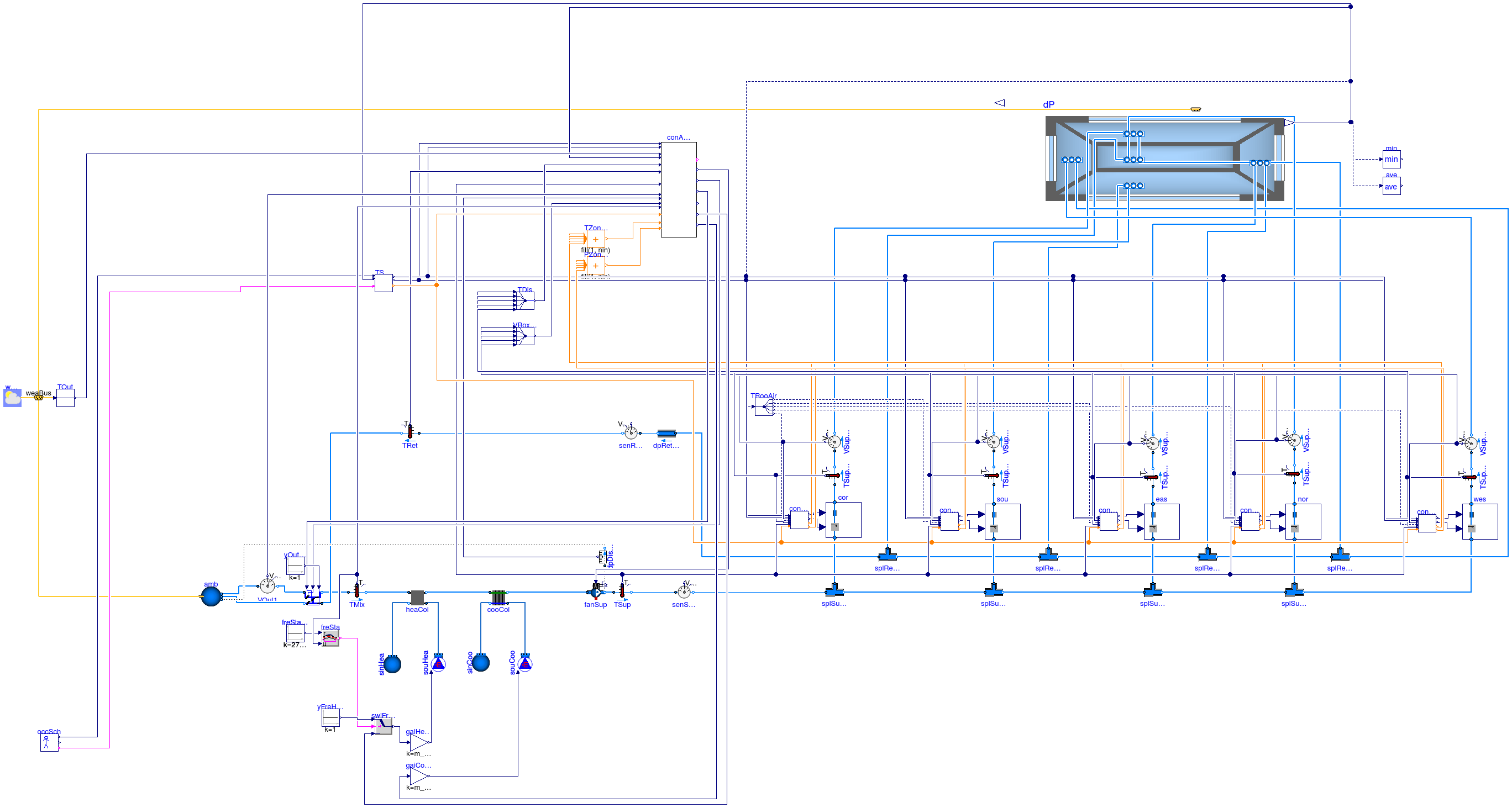
This model consist of an HVAC system, a building envelope model and a model
for air flow through building leakage and through open doors.
The HVAC system is a variable air volume (VAV) flow system with economizer
and a heating and cooling coil in the air handler unit. There is also a
reheat coil and an air damper in each of the five zone inlet branches.
See the model
Buildings.Examples.VAVReheat.BaseClasses.PartialOpenLoop
for a description of the HVAC system and the building envelope.
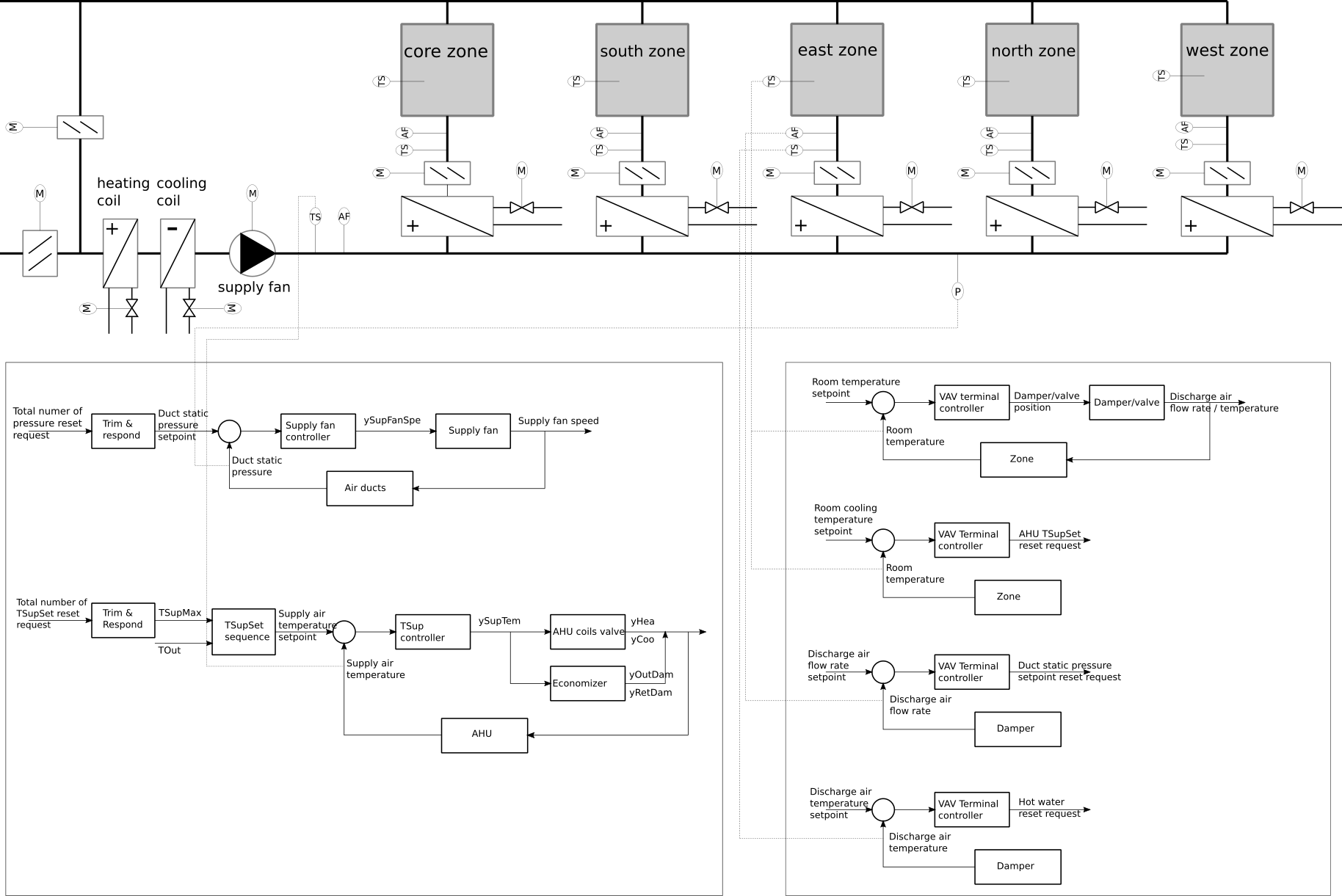
The control is based on ASHRAE Guideline 36, and implemented
using the sequences from the library
Buildings.Controls.OBC.ASHRAE.G36_PR1 for
multi-zone VAV systems with economizer. The schematic diagram of the HVAC and control
sequence is shown in the figure below.
A similar model but with a different control sequence can be found in
Buildings.Examples.VAVReheat.ASHRAE2006.
Note that this model, because of the frequent time sampling,
has longer computing time than
Buildings.Examples.VAVReheat.ASHRAE2006.
The reason is that the time integrator cannot make large steps
because it needs to set a time step each time the control samples
its input.
Extends from Modelica.Icons.Example (Icon for runnable examples), Buildings.Examples.VAVReheat.BaseClasses.PartialOpenLoop (Partial model of variable air volume flow system with terminal reheat and five thermal zones).
Parameters
| Type | Name | Default | Description |
|---|
| Volume | VRooCor | AFloCor*flo.hRoo | Room volume corridor [m3] |
| Volume | VRooSou | AFloSou*flo.hRoo | Room volume south [m3] |
| Volume | VRooNor | AFloNor*flo.hRoo | Room volume north [m3] |
| Volume | VRooEas | AFloEas*flo.hRoo | Room volume east [m3] |
| Volume | VRooWes | AFloWes*flo.hRoo | Room volume west [m3] |
| Area | AFloCor | flo.cor.AFlo | Floor area corridor [m2] |
| Area | AFloSou | flo.sou.AFlo | Floor area south [m2] |
| Area | AFloNor | flo.nor.AFlo | Floor area north [m2] |
| Area | AFloEas | flo.eas.AFlo | Floor area east [m2] |
| Area | AFloWes | flo.wes.AFlo | Floor area west [m2] |
| Area | AFlo[numZon] | {flo.cor.AFlo,flo.sou.AFlo,f... | Floor area of each zone [m2] |
| MassFlowRate | mCor_flow_nominal | 6*VRooCor*conv | Design mass flow rate core [kg/s] |
| MassFlowRate | mSou_flow_nominal | 6*VRooSou*conv | Design mass flow rate perimeter 1 [kg/s] |
| MassFlowRate | mEas_flow_nominal | 9*VRooEas*conv | Design mass flow rate perimeter 2 [kg/s] |
| MassFlowRate | mNor_flow_nominal | 6*VRooNor*conv | Design mass flow rate perimeter 3 [kg/s] |
| MassFlowRate | mWes_flow_nominal | 7*VRooWes*conv | Design mass flow rate perimeter 4 [kg/s] |
| MassFlowRate | m_flow_nominal | 0.7*(mCor_flow_nominal + mSo... | Nominal mass flow rate [kg/s] |
| Angle | lat | 41.98*3.14159/180 | Latitude [rad] |
| Temperature | THeaOn | 293.15 | Heating setpoint during on [K] |
| Temperature | THeaOff | 285.15 | Heating setpoint during off [K] |
| Temperature | TCooOn | 297.15 | Cooling setpoint during on [K] |
| Temperature | TCooOff | 303.15 | Cooling setpoint during off [K] |
| PressureDifference | dpBuiStaSet | 12 | Building static pressure [Pa] |
| Real | yFanMin | 0.1 | Minimum fan speed |
| Boolean | allowFlowReversal | true | = false to simplify equations, assuming, but not enforcing, no flow reversal |
| Boolean | use_windPressure | true | Set to true to enable wind pressure |
| VolumeFlowRate | maxSysPriFlo | m_flow_nominal/1.2 | Maximum expected system primary airflow rate at design stage [m3/s] |
| VolumeFlowRate | minZonPriFlo[numZon] | {mCor_flow_nominal,mSou_flow... | Minimum expected zone primary flow rate [m3/s] |
| Time | samplePeriod | 120 | Sample period of component, set to the same value as the trim and respond that process yPreSetReq [s] |
| PressureDifference | dpDisRetMax | 40 | Maximum return fan discharge static pressure setpoint [Pa] |
| Experimental (may be changed in future releases) |
| Boolean | sampleModel | true | Set to true to time-sample the model, which can give shorter simulation time if there is already time sampling in the system model |
Connectors
| Type | Name | Description |
|---|
| Bus | weaBus | Weather Data Bus |
Modelica definition
model Guideline36
extends Modelica.Icons.Example;
extends Buildings.Examples.VAVReheat.BaseClasses.PartialOpenLoop;
parameter Modelica.SIunits.VolumeFlowRate maxSysPriFlo=m_flow_nominal/1.2 ;
parameter Modelica.SIunits.VolumeFlowRate minZonPriFlo[numZon]={
mCor_flow_nominal,mSou_flow_nominal,mEas_flow_nominal,mNor_flow_nominal,
mWes_flow_nominal}/1.2 ;
parameter Modelica.SIunits.Time samplePeriod=120 ;
parameter Modelica.SIunits.PressureDifference dpDisRetMax=40 ;
Buildings.Controls.OBC.ASHRAE.G36_PR1.TerminalUnits.Controller conVAVCor(
V_flow_nominal=mCor_flow_nominal/1.2,
AFlo=AFloCor,
final samplePeriod=samplePeriod) ;
Buildings.Controls.OBC.ASHRAE.G36_PR1.TerminalUnits.Controller conVAVSou(
V_flow_nominal=mSou_flow_nominal/1.2,
AFlo=AFloSou,
final samplePeriod=samplePeriod) ;
Buildings.Controls.OBC.ASHRAE.G36_PR1.TerminalUnits.Controller conVAVEas(
V_flow_nominal=mEas_flow_nominal/1.2,
AFlo=AFloEas,
final samplePeriod=samplePeriod) ;
Buildings.Controls.OBC.ASHRAE.G36_PR1.TerminalUnits.Controller conVAVNor(
V_flow_nominal=mNor_flow_nominal/1.2,
AFlo=AFloNor,
final samplePeriod=samplePeriod) ;
Buildings.Controls.OBC.ASHRAE.G36_PR1.TerminalUnits.Controller conVAVWes(
V_flow_nominal=mWes_flow_nominal/1.2,
AFlo=AFloWes,
final samplePeriod=samplePeriod) ;
Buildings.Controls.OBC.ASHRAE.G36_PR1.AHUs.MultiZone.Controller conAHU(
numZon=numZon,
maxSysPriFlo=maxSysPriFlo,
minZonPriFlo=minZonPriFlo,
AFlo=AFlo,
yFanMin=yFanMin,
pMaxSet=410) ;
Buildings.Controls.OBC.ASHRAE.G36_PR1.TerminalUnits.ModeAndSetPoints TSetZon(
THeaOn=THeaOn,
THeaOff=THeaOff,
TCooOff=TCooOff,
numZon=numZon) ;
Modelica.Blocks.Routing.Multiplex5 TDis ;
Modelica.Blocks.Routing.Multiplex5 VBox_flow ;
Buildings.Controls.OBC.CDL.Integers.MultiSum TZonResReq(nin=5) ;
Buildings.Controls.OBC.CDL.Integers.MultiSum PZonResReq(nin=5) ;
Buildings.Controls.OBC.CDL.Continuous.Sources.Constant yOutDam(k=1) ;
Buildings.Controls.OBC.CDL.Logical.Switch swiFreSta ;
Buildings.Controls.OBC.CDL.Continuous.Sources.Constant freStaSetPoi1(k=273.15 +
3) ;
Buildings.Controls.OBC.CDL.Continuous.Sources.Constant yFreHeaCoi(
final k=1) ;
equation
connect(fanSup.port_b, dpDisSupFan.port_a);
connect(conVAVCor.TRoo, TRooAir.y5[1]);
connect(conVAVSou.TRoo, TRooAir.y1[1]);
connect(TRooAir.y2[1], conVAVEas.TRoo);
connect(TRooAir.y3[1], conVAVNor.TRoo);
connect(TRooAir.y4[1], conVAVWes.TRoo);
connect(conVAVCor.TDis, TSupCor.T);
connect(TSupSou.T, conVAVSou.TDis);
connect(TSupEas.T, conVAVEas.TDis);
connect(TSupNor.T, conVAVNor.TDis);
connect(TSupWes.T, conVAVWes.TDis);
connect(cor.yVAV, conVAVCor.yDam);
connect(cor.yVal, conVAVCor.yVal);
connect(conVAVSou.yDam, sou.yVAV);
connect(conVAVSou.yVal, sou.yVal);
connect(conVAVEas.yVal, eas.yVal);
connect(conVAVEas.yDam, eas.yVAV);
connect(conVAVNor.yDam, nor.yVAV);
connect(conVAVNor.yVal, nor.yVal);
connect(conVAVCor.TRooHeaSet, TSetZon.THeaSet[1]);
connect(conVAVCor.TRooCooSet, TSetZon.TCooSet[1]);
connect(conVAVSou.TRooHeaSet, TSetZon.THeaSet[2]);
connect(conVAVSou.TRooCooSet, TSetZon.TCooSet[2]);
connect(conVAVEas.TRooHeaSet, TSetZon.THeaSet[3]);
connect(conVAVEas.TRooCooSet, TSetZon.TCooSet[3]);
connect(conVAVNor.TRooHeaSet, TSetZon.THeaSet[4]);
connect(conVAVNor.TRooCooSet, TSetZon.TCooSet[4]);
connect(conVAVWes.TRooHeaSet, TSetZon.THeaSet[5]);
connect(conVAVWes.TRooCooSet, TSetZon.TCooSet[5]);
connect(conVAVWes.yVal, wes.yVal);
connect(wes.yVAV, conVAVWes.yDam);
connect(TSetZon.uOcc, occSch.occupied);
connect(occSch.tNexOcc, TSetZon.tNexOcc);
connect(TSetZon.TZon, flo.TRooAir);
connect(conAHU.THeaSet, TSetZon.THeaSet[1]);
connect(conAHU.TCooSet, TSetZon.TCooSet[1]);
connect(conAHU.TZon, flo.TRooAir);
connect(conAHU.TOut, TOut.y);
connect(TRet.T, conAHU.TOutCut);
connect(conAHU.TSup, TSup.T);
connect(dpDisSupFan.p_rel, conAHU.ducStaPre);
connect(conAHU.uOpeMod, TSetZon.yOpeMod);
connect(conAHU.TDis, TDis.y);
connect(conAHU.VBox_flow, VBox_flow.y);
connect(conVAVCor.uOpeMod, TSetZon.yOpeMod);
connect(conVAVSou.uOpeMod, TSetZon.yOpeMod);
connect(conVAVEas.uOpeMod, TSetZon.yOpeMod);
connect(conVAVNor.uOpeMod, TSetZon.yOpeMod);
connect(conVAVWes.uOpeMod, TSetZon.yOpeMod);
connect(conAHU.uZonTemResReq, TZonResReq.y);
connect(conVAVCor.yZonTemResReq, TZonResReq.u[1]);
connect(conVAVSou.yZonTemResReq, TZonResReq.u[2]);
connect(conVAVEas.yZonTemResReq, TZonResReq.u[3]);
connect(conVAVNor.yZonTemResReq, TZonResReq.u[4]);
connect(conVAVWes.yZonTemResReq, TZonResReq.u[5]);
connect(conVAVCor.yZonPreResReq, PZonResReq.u[1]);
connect(conVAVSou.yZonPreResReq, PZonResReq.u[2]);
connect(conVAVEas.yZonPreResReq, PZonResReq.u[3]);
connect(conVAVNor.yZonPreResReq, PZonResReq.u[4]);
connect(conVAVWes.yZonPreResReq, PZonResReq.u[5]);
connect(conAHU.uZonPreResReq, PZonResReq.y);
connect(VSupCor_flow.V_flow, VBox_flow.u1[1]);
connect(VSupSou_flow.V_flow, VBox_flow.u2[1]);
connect(VSupEas_flow.V_flow, VBox_flow.u3[1]);
connect(VSupNor_flow.V_flow, VBox_flow.u4[1]);
connect(VSupWes_flow.V_flow, VBox_flow.u5[1]);
connect(TSupCor.T, TDis.u1[1]);
connect(TSupSou.T, TDis.u2[1]);
connect(TSupEas.T, TDis.u3[1]);
connect(TSupNor.T, TDis.u4[1]);
connect(TSupWes.T, TDis.u5[1]);
connect(conAHU.yOutDamPos, eco.yOut);
connect(conVAVCor.VDis, VSupCor_flow.V_flow);
connect(VSupSou_flow.V_flow, conVAVSou.VDis);
connect(VSupEas_flow.V_flow, conVAVEas.VDis);
connect(VSupNor_flow.V_flow, conVAVNor.VDis);
connect(VSupWes_flow.V_flow, conVAVWes.VDis);
connect(TSup.T, conVAVCor.TSupAHU);
connect(TSup.T, conVAVSou.TSupAHU);
connect(TSup.T, conVAVEas.TSupAHU);
connect(TSup.T, conVAVNor.TSupAHU);
connect(TSup.T, conVAVWes.TSupAHU);
connect(VOut1.V_flow, conAHU.VOut_flow);
connect(fanSup.y, conAHU.ySupFanSpe);
connect(conAHU.yCoo, gaiCooCoi.u);
connect(conAHU.TMix, TMix.T);
connect(conAHU.yRetDamPos, eco.yRet);
connect(yOutDam.y, eco.yExh);
connect(conAHU.yHea, swiFreSta.u3);
connect(swiFreSta.y, gaiHeaCoi.u);
connect(freSta.y, swiFreSta.u2);
connect(yFreHeaCoi.y, swiFreSta.u1);
end Guideline36;
 Buildings.Examples.VAVReheat.ASHRAE2006