Output setpoints for AHU control
Information
This package contains sequences generating setpoints for VAV AHU control.
Extends from Modelica.Icons.Package (Icon for standard packages).
Package Content
| Name |
Description |
 ExhaustDamper ExhaustDamper
|
Control of actuated exhaust air dampers without fans |
 OutsideAirFlow OutsideAirFlow
|
Output the minimum outdoor airflow rate setpoint for systems with multiple zones |
 ReturnFanDirectPressure ReturnFanDirectPressure
|
Return fan control with direct building pressure control |
 VAVSupplyFan VAVSupplyFan
|
Block to control multi zone VAV AHU supply fan |
 VAVSupplySignals VAVSupplySignals
|
Multizone VAV AHU coil valve positions |
 VAVSupplyTemperature VAVSupplyTemperature
|
Supply air temperature setpoint for multi zone system |
 Validation Validation
|
Collection of validation models |
Control of actuated exhaust air dampers without fans
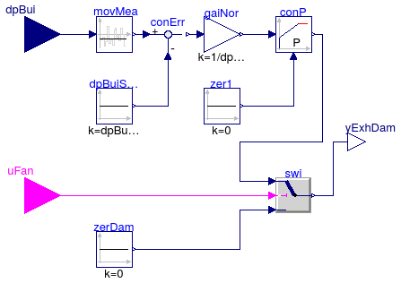
Information
Control sequence for actuated exhaust damper yExhDamPos
without fans. It is implemented according to ASHRAE Guidline 35 (G36), PART5.N.8.
(for multi zone VAV AHU), PART5.P.6 and PART3.2B.3 (for single zone VAV AHU).
Multi zone VAV AHU: Control of actuated exhaust dampers without fans (PART5.N.8)
- The exhaust damper is enabled when the associated supply fan is proven on
uSupFan = true, and disabled otherwise.
- When enabled, a P-only control loop modulates the exhaust damper to maintain
a building static pressure of
uBuiPre, which is by default 12 Pa (0.05 inchWC).
-
When
uSupFan = false, the damper is closed.
Parameters
| Type | Name | Default | Description |
|---|
| PressureDifference | dpBuiSet | 12 | Building static pressure difference relative to ambient (positive to pressurize the building) [Pa] |
| Exhaust damper P-control parameter |
| Real | k | 0.5 | Gain, applied to building pressure control error normalized with dpBuiSet [1] |
Connectors
| Type | Name | Description |
|---|
| input RealInput | dpBui | Building static pressure difference, relative to ambient (positive if pressurized) [Pa] |
| input BooleanInput | uFan | Supply fan status |
| output RealOutput | yExhDam | Exhaust damper control signal (0: closed, 1: open) [1] |
Modelica definition
block ExhaustDamper
parameter Modelica.SIunits.PressureDifference dpBuiSet(
displayUnit="Pa",
max=30) = 12 ;
parameter Real k(
min=0,
unit="1") = 0.5 ;
Buildings.Controls.OBC.CDL.Interfaces.RealInput dpBui(
final unit="Pa",
displayUnit="Pa") ;
Buildings.Controls.OBC.CDL.Interfaces.BooleanInput uFan ;
Buildings.Controls.OBC.CDL.Interfaces.RealOutput yExhDam(
final unit="1",
min=0,
max=1) ;
Buildings.Controls.OBC.CDL.Continuous.MovingMean movMea(delta=300) ;
Buildings.Controls.OBC.CDL.Continuous.Feedback conErr(
u1(
final unit="Pa", displayUnit="Pa"),
u2(
final unit="Pa", displayUnit="Pa"),
y(
final unit="Pa", displayUnit="Pa")) ;
Buildings.Controls.OBC.CDL.Continuous.LimPID conP(
final controllerType=Buildings.Controls.OBC.CDL.Types.SimpleController.P,
final k=k,
yMax=1,
yMin=0) ;
Buildings.Controls.OBC.CDL.Logical.Switch swi ;
protected
Buildings.Controls.OBC.CDL.Continuous.Sources.Constant zerDam(
final k=0) ;
Buildings.Controls.OBC.CDL.Continuous.Sources.Constant dpBuiSetPoi1(
final k=
dpBuiSet) ;
Buildings.Controls.OBC.CDL.Continuous.Gain gaiNor(
final k=1/dpBuiSet) ;
Buildings.Controls.OBC.CDL.Continuous.Sources.Constant zer1(
final k=0) ;
equation
connect(uFan, swi.u2);
connect(zerDam.y, swi.u3);
connect(swi.y, yExhDam);
connect(dpBui, movMea.u);
connect(movMea.y, conErr.u1);
connect(conErr.y, gaiNor.u);
connect(gaiNor.y, conP.u_s);
connect(dpBuiSetPoi1.y, conErr.u2);
connect(zer1.y, conP.u_m);
connect(conP.y, swi.u1);
end ExhaustDamper;
Output the minimum outdoor airflow rate setpoint for systems with multiple zones
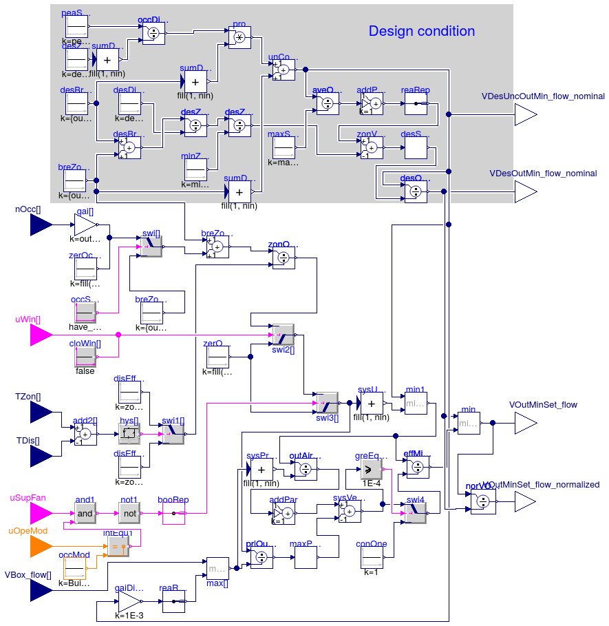
Information
This atomic sequence sets the minimum outdoor airflow setpoint for compliance
with the ventilation rate procedure of ASHRAE 62.1-2013. The implementation
is according to ASHRAE Guidline 36 (G36), PART5.N.3.a, PART5.B.2.b,
PART3.1-D.2.a.
The calculation is done using the steps below.
Step 1: Minimum breathing zone outdoor airflow required breZon
- The area component of the breathing zone outdoor airflow:
breZonAre = AFlo*outAirPerAre.
- The population component of the breathing zone outdoor airflow:
breZonPop = occCou*outAirPerPer.
The number of occupant occCou in each zone can be retrieved
directly from occupancy sensor nOcc if the sensor exists
(have_occSen=true), or using the default occupant density
occDen to find it AFlo*occDen. The occupant
density can be found from Table 6.2.2.1 in ASHRAE Standard 62.1-2013.
For design purpose, use design zone population desZonPop to find
out the minimum requirement at the ventilation-design condition.
Step 2: Zone air-distribution effectiveness zonDisEff
Table 6.2.2.2 in ASHRAE 62.1-2013 lists some typical values for setting the
effectiveness. Depending on difference between zone space temperature
TZon and discharge air temperature (after the reheat coil) TDis, Warm-air
effectiveness zonDisEffHea or Cool-air effectiveness
zonDisEffCoo should be applied.
Step 3: Minimum required zone outdoor airflow zonOutAirRate
For each zone in any mode other than occupied mode and for zones that have
window switches and the window is open, zonOutAirRate shall be
zero.
Otherwise, the required zone outdoor airflow zonOutAirRate
shall be calculated as follows:
If the zone is populated, or if there is no occupancy sensor:
-
If discharge air temperature at the terminal unit is less than or equal to
zone space temperature:
zonOutAirRate = (breZonAre+breZonPop)/disEffCoo.
-
If discharge air temperature at the terminal unit is greater than zone space
temperature:
zonOutAirRate = (breZonAre+breZonPop)/disEffHea
If the zone has an occupancy sensor and is unpopulated:
-
If discharge air temperature at the terminal unit is less than or equal to
zone space temperature:
zonOutAirRate = breZonAre/disEffCoo
-
If discharge air temperature at the terminal unit is greater than zone
space temperature:
zonOutAirRate = breZonAre/disEffHea
Step 4: Outdoor air fraction for each zone priOutAirFra
The zone outdoor air fraction:
priOutAirFra = zonOutAirRate/VBox_flow
where,
VBox_flow is measured from zone VAV box.
For design purpose, the design zone outdoor air fraction
desZonPriOutAirRate
is found by
desZonPriOutAirRate = desZonOutAirRate/minZonFlo
where
minZonFlo is the minimum expected zone primary flow rate and
desZonOutAirRate is required design zone outdoor airflow rate.
Step 5: Occupancy diversity fractionoccDivFra
For actual system operation, the system population equals the sum of zone population,
so
occDivFra=1. It has no impact on the calculation of uncorrected
outdoor airflow
sysUncOutAir.
For design purpose, find
occDivFra based on the peak system population
peaSysPopulation and the sum of design population
desZonPopulation
for all zones:
occDivFra = peaSysPopulation/sum(desZonPopulation)
Step 6: Uncorrected outdoor airflow unCorOutAirInk,
sysUncOutAir
unCorOutAirInk = occDivFra*sum(breZonPop)+sum(breZonAre)
Step 7: System primary airflow sysPriAirRate
The system primary airflow equals to the sum of discharge airflow rate measured
from each VAV box
VBox_flow.
For design purpose, a highest expected system primary airflow
maxSysPriFlow
should be applied. It usually is usually estimated with load-diversity factor,
e.g. 0.7. (Stanke, 2010)
Step 8: Outdoor air fraction
The average outdoor air fraction should be found as following:
outAirFra = sysUncOutAir/sysPriAirRate
For design purpose, it should be found as:
aveOutAirFra = unCorOutAirInk/maxSysPriFlow
Step 9: Zone ventilation efficiency zonVenEff (for design purpose)
zonVenEff[i] = 1 + aveOutAirFra + desZonPriOutAirRate[i]
where the
desZonPriOutAirRate is design zone outdoor airflow fraction.
Step 10: System ventilation efficiency
In actual system operation, the system ventilation efficiency
sysVenEff:
sysVenEff = 1 + outAirFra + MAX(priOutAirFra[i])
Design system ventilation efficiency
desSysVenEff:
desSysVenEff = MIN(zonVenEff[i])
Step 11: Minimum required system outdoor air intake flow
The minimum required system outdoor air intake flow should be the uncorrected
outdoor air intake
sysUncOutAir divided by the system ventilation
efficiency
sysVenEff, but should not be larger than the design
outdoor air rate
desOutAirInt.
effMinOutAirInt = MIN(sysUncOutAir/sysVenEff, desOutAirInt)
where the design outdoor air rate
desOutAirInt should be:
desOutAirInt = unCorOutAirInk/desSysVenEff
References
ANSI/ASHRAE Standard 62.1-2013,
Ventilation for Acceptable Indoor Air Quality.
Stanke, D., 2010. Dynamic Reset for Multiple-Zone Systems. ASHRAE Journal, March
2010.
Parameters
| Type | Name | Default | Description |
|---|
| Integer | numZon | | Total number of zones that the system serves |
| Boolean | have_occSen | true | Set to true if zones have occupancy sensor |
| Boolean | have_winSen | true | Set to true if zones have window status sensor |
| Real | occDen[numZon] | fill(0.05, numZon) | Default number of person in unit area [1/m2] |
| Real | zonDisEffHea[numZon] | fill(0.8, numZon) | Zone air distribution effectiveness during heating [1] |
| Real | zonDisEffCoo[numZon] | fill(1.0, numZon) | Zone air distribution effectiveness during cooling [1] |
| Nominal condition |
| Real | outAirPerAre[numZon] | fill(3e-4, numZon) | Outdoor air rate per unit area [m3/(s.m2)] |
| VolumeFlowRate | outAirPerPer[numZon] | fill(2.5e-3, numZon) | Outdoor air rate per person [m3/s] |
| Area | AFlo[numZon] | | Floor area of each zone [m2] |
| Real | desZonDisEff[numZon] | fill(1.0, numZon) | Design zone air distribution effectiveness [1] |
| Real | desZonPop[numZon] | {occDen[i]*AFlo[i] for i in ... | Design zone population during peak occupancy [1] |
| VolumeFlowRate | maxSysPriFlo | | Maximum expected system primary airflow at design stage [m3/s] |
| VolumeFlowRate | minZonPriFlo[numZon] | | Minimum expected zone primary flow rate [m3/s] |
| Real | peaSysPop | 1.2*sum({occDen[iZon]*AFlo[i... | Peak system population [1] |
| Advanced |
| Real | uLow | -0.5 | If zone space temperature minus supply air temperature is less than uLow,
then it should use heating supply air distribution effectiveness [K] |
| Real | uHig | 0.5 | If zone space temperature minus supply air temperature is more than uHig,
then it should use cooling supply air distribution effectiveness [K] |
Connectors
| Type | Name | Description |
|---|
| input RealInput | nOcc[numZon] | Number of occupants [1] |
| input RealInput | VBox_flow[numZon] | Primary airflow rate to the ventilation zone from the air handler, including outdoor air and recirculated air [m3/s] |
| input RealInput | TZon[numZon] | Measured zone air temperature [K] |
| input RealInput | TDis[numZon] | Measured discharge air temperature [K] |
| input IntegerInput | uOpeMod | AHU operation mode status signal |
| input BooleanInput | uSupFan | Supply fan status, true if on, false if off |
| input BooleanInput | uWin[numZon] | Window status, true if open, false if closed |
| output RealOutput | VDesOutMin_flow_nominal | Design minimum outdoor airflow rate [m3/s] |
| output RealOutput | VDesUncOutMin_flow_nominal | Design uncorrected minimum outdoor airflow rate [m3/s] |
| output RealOutput | VOutMinSet_flow | Effective minimum outdoor airflow setpoint [m3/s] |
| output RealOutput | VOutMinSet_flow_normalized | Effective minimum outdoor airflow setpoint, normalized by VDesOutMin_flow_nominal [1] |
Modelica definition
block OutsideAirFlow
parameter Integer numZon(min=2) ;
parameter Real outAirPerAre[numZon](
each final unit="m3/(s.m2)") =
fill(3e-4,
numZon) ;
parameter Modelica.SIunits.VolumeFlowRate outAirPerPer[numZon]=
fill(2.5e-3,
numZon) ;
parameter Modelica.SIunits.Area AFlo[numZon] ;
parameter Boolean have_occSen=true ;
parameter Boolean have_winSen=true ;
parameter Real occDen[numZon](
each final unit="1/m2") =
fill(0.05, numZon) ;
parameter Real zonDisEffHea[numZon](
each final unit="1") =
fill(0.8, numZon) ;
parameter Real zonDisEffCoo[numZon](
each final unit="1") =
fill(1.0, numZon) ;
parameter Real desZonDisEff[numZon](
each unit="1") =
fill(1.0, numZon) ;
parameter Real desZonPop[numZon](
min={occDen[i]*AFlo[i]
for i
in 1:numZon},
each unit="1") = {occDen[i]*AFlo[i]
for i
in 1:numZon} ;
parameter Real uLow(
final unit="K",
displayUnit="K",
quantity="ThermodynamicTemperature") = -0.5 ;
parameter Real uHig(
final unit="K",
displayUnit="K",
quantity="ThermodynamicTemperature") = 0.5 ;
parameter Modelica.SIunits.VolumeFlowRate maxSysPriFlo ;
parameter Modelica.SIunits.VolumeFlowRate minZonPriFlo[numZon] ;
parameter Real peaSysPop(unit="1") = 1.2*
sum({occDen[iZon]*AFlo[iZon]
for
iZon
in 1:numZon}) ;
Buildings.Controls.OBC.CDL.Interfaces.RealInput nOcc[numZon](
each final unit="1")
if have_occSen ;
Buildings.Controls.OBC.CDL.Interfaces.RealInput VBox_flow[numZon](
min=0,
each final unit="m3/s",
each quantity="VolumeFlowRate") ;
Buildings.Controls.OBC.CDL.Interfaces.RealInput TZon[numZon](
each final unit="K",
each quantity="ThermodynamicTemperature") ;
Buildings.Controls.OBC.CDL.Interfaces.RealInput TDis[numZon](
each final unit="K",
each quantity="ThermodynamicTemperature") ;
Buildings.Controls.OBC.CDL.Interfaces.IntegerInput uOpeMod ;
Buildings.Controls.OBC.CDL.Interfaces.BooleanInput uSupFan ;
Buildings.Controls.OBC.CDL.Interfaces.BooleanInput uWin[numZon]
if
have_winSen ;
Buildings.Controls.OBC.CDL.Interfaces.RealOutput VDesOutMin_flow_nominal(
min=0,
final unit="m3/s",
quantity="VolumeFlowRate") ;
Buildings.Controls.OBC.CDL.Interfaces.RealOutput VDesUncOutMin_flow_nominal(
min=0,
final unit="m3/s",
quantity="VolumeFlowRate") ;
Buildings.Controls.OBC.CDL.Interfaces.RealOutput VOutMinSet_flow(
min=0,
final unit="m3/s",
quantity="VolumeFlowRate") ;
CDL.Interfaces.RealOutput VOutMinSet_flow_normalized(
final unit="1") ;
protected
Buildings.Controls.OBC.CDL.Continuous.Add breZon[numZon] ;
Buildings.Controls.OBC.CDL.Continuous.Gain gai[numZon](
final k=outAirPerPer)
if have_occSen ;
Buildings.Controls.OBC.CDL.Logical.Switch swi[numZon] ;
Buildings.Controls.OBC.CDL.Logical.Switch swi1[numZon] ;
Buildings.Controls.OBC.CDL.Continuous.Division zonOutAirRate[numZon] ;
Buildings.Controls.OBC.CDL.Logical.Not not1 ;
Buildings.Controls.OBC.CDL.Logical.Switch swi2[numZon] ;
Buildings.Controls.OBC.CDL.Logical.Switch swi3[numZon] ;
Buildings.Controls.OBC.CDL.Continuous.Max max[numZon] ;
Buildings.Controls.OBC.CDL.Continuous.Division priOutAirFra[numZon] ;
Buildings.Controls.OBC.CDL.Continuous.MultiSum sysUncOutAir(
final nin=numZon)
;
Buildings.Controls.OBC.CDL.Continuous.MultiSum sysPriAirRate(
final nin=numZon)
;
Buildings.Controls.OBC.CDL.Continuous.Division outAirFra ;
Buildings.Controls.OBC.CDL.Continuous.AddParameter addPar(
final p=1,
final k=1)
;
Buildings.Controls.OBC.CDL.Continuous.Add sysVenEff(
final k2=-1) ;
Buildings.Controls.OBC.CDL.Continuous.Division effMinOutAirInt ;
Buildings.Controls.OBC.CDL.Continuous.Add desBreZon[numZon] ;
Buildings.Controls.OBC.CDL.Continuous.Division desZonOutAirRate[numZon] ;
Buildings.Controls.OBC.CDL.Continuous.Division desZonPriOutAirRate[numZon] ;
Buildings.Controls.OBC.CDL.Continuous.MultiSum sumDesZonPop(
final nin=numZon)
;
Buildings.Controls.OBC.CDL.Continuous.Division occDivFra ;
Buildings.Controls.OBC.CDL.Continuous.MultiSum sumDesBreZonPop(
final nin=
numZon) ;
Buildings.Controls.OBC.CDL.Continuous.MultiSum sumDesBreZonAre(
final nin=
numZon) ;
Buildings.Controls.OBC.CDL.Continuous.Add unCorOutAirInk ;
Buildings.Controls.OBC.CDL.Continuous.Product pro ;
Buildings.Controls.OBC.CDL.Continuous.Division aveOutAirFra ;
Buildings.Controls.OBC.CDL.Continuous.AddParameter addPar1(
final p=1,
final k
=1) ;
Buildings.Controls.OBC.CDL.Continuous.Add zonVenEff[numZon](
each final k2=-1)
;
Buildings.Controls.OBC.CDL.Continuous.Add add2[numZon](
each final k1=+1,
each final k2=-1) ;
Buildings.Controls.OBC.CDL.Continuous.Division desOutAirInt ;
Buildings.Controls.OBC.CDL.Continuous.MultiMin desSysVenEff(nin=numZon) ;
Buildings.Controls.OBC.CDL.Continuous.MultiMax maxPriOutAirFra(nin=numZon) ;
Buildings.Controls.OBC.CDL.Continuous.Min min ;
Buildings.Controls.OBC.CDL.Continuous.Min min1 ;
Buildings.Controls.OBC.CDL.Continuous.Hysteresis hys[numZon](
each uLow=uLow,
each uHigh=uHig,
each pre_y_start=true) ;
Buildings.Controls.OBC.CDL.Logical.Sources.Constant occSen[numZon](
each
final k=have_occSen) ;
Buildings.Controls.OBC.CDL.Integers.Sources.Constant occMod(k=Buildings.Controls.OBC.ASHRAE.G36_PR1.Types.OperationModes.occupied)
;
Buildings.Controls.OBC.CDL.Continuous.Sources.Constant desDisEff[numZon](k=
desZonDisEff) ;
Buildings.Controls.OBC.CDL.Continuous.Sources.Constant minZonFlo[numZon](k=
minZonPriFlo) ;
Buildings.Controls.OBC.CDL.Continuous.Sources.Constant breZonAre[numZon](k={
outAirPerAre[i]*AFlo[i]
for i
in 1:numZon}) ;
Buildings.Controls.OBC.CDL.Continuous.Sources.Constant breZonPop[numZon](k={
outAirPerPer[i]*AFlo[i]*occDen[i]
for i
in 1:numZon}) ;
Buildings.Controls.OBC.CDL.Continuous.Sources.Constant disEffHea[numZon](k=
zonDisEffHea) ;
Buildings.Controls.OBC.CDL.Continuous.Sources.Constant disEffCoo[numZon](k=
zonDisEffCoo) ;
Buildings.Controls.OBC.CDL.Continuous.Sources.Constant desZonPopulation[
numZon](k=desZonPop) ;
Buildings.Controls.OBC.CDL.Continuous.Sources.Constant zerOutAir[numZon](k=
fill(0, numZon)) ;
Buildings.Controls.OBC.CDL.Continuous.Sources.Constant desBreZonPer[numZon](k
={outAirPerPer[i]*desZonPop[i]
for i
in 1:numZon}) ;
Buildings.Controls.OBC.CDL.Continuous.Sources.Constant peaSysPopulation(k=
peaSysPop) ;
Buildings.Controls.OBC.CDL.Continuous.Sources.Constant maxSysPriFlow(k=
maxSysPriFlo) ;
Buildings.Controls.OBC.CDL.Routing.BooleanReplicator booRep(nout=numZon) ;
Buildings.Controls.OBC.CDL.Routing.RealReplicator reaRep(nout=numZon) ;
Buildings.Controls.OBC.CDL.Integers.Equal intEqu1 ;
Buildings.Controls.OBC.CDL.Logical.And and1 ;
Buildings.Controls.OBC.CDL.Continuous.Gain gaiDivZer(
final k=1E-3) ;
Buildings.Controls.OBC.CDL.Routing.RealReplicator reaRepDivZer(
final nout=
numZon) ;
Buildings.Controls.OBC.CDL.Logical.Switch swi4 ;
Buildings.Controls.OBC.CDL.Continuous.Sources.Constant conOne(k=1) ;
Buildings.Controls.OBC.CDL.Continuous.GreaterEqualThreshold greEquThr(
threshold=1E-4) ;
Buildings.Controls.OBC.CDL.Continuous.Sources.Constant zerOcc[numZon](k=
fill(0,
numZon))
if not have_occSen ;
Buildings.Controls.OBC.CDL.Logical.Sources.Constant cloWin[numZon](
each
final k=false)
if not have_winSen ;
CDL.Continuous.Division norVOutMin ;
equation
connect(breZonAre.y, breZon.u1);
connect(gai.y, swi.u1);
connect(breZonPop.y, swi.u3);
connect(gai.u, nOcc);
connect(swi.y, breZon.u2);
connect(disEffCoo.y, swi1.u1);
connect(disEffHea.y, swi1.u3);
connect(breZon.y, zonOutAirRate.u1);
connect(swi1.y, zonOutAirRate.u2);
connect(uWin, swi2.u2);
connect(zerOutAir.y, swi2.u1);
connect(zonOutAirRate.y, swi2.u3);
connect(swi2.y, swi3.u3);
connect(zerOutAir.y, swi3.u1);
connect(swi3.y, priOutAirFra.u1);
connect(swi3.y, sysUncOutAir.u);
connect(breZonAre.y, desBreZon.u2);
connect(desBreZonPer.y, desBreZon.u1);
connect(desDisEff.y, desZonOutAirRate.u2);
connect(desBreZon.y, desZonOutAirRate.u1);
connect(desZonOutAirRate.y, desZonPriOutAirRate.u1);
connect(minZonFlo.y, desZonPriOutAirRate.u2);
connect(desZonPopulation.y, sumDesZonPop.u);
connect(desBreZonPer.y, sumDesBreZonPop.u);
connect(breZonAre.y, sumDesBreZonAre.u);
connect(desZonPriOutAirRate.y, zonVenEff.u2);
connect(swi.u2, occSen.y);
connect(TDis, add2.u2);
connect(TZon, add2.u1);
connect(add2.y, hys.u);
connect(hys.y, swi1.u2);
connect(max.y, priOutAirFra.u2);
connect(max.y, sysPriAirRate.u);
connect(priOutAirFra.y, maxPriOutAirFra.u);
connect(sysPriAirRate.y, outAirFra.u2);
connect(maxPriOutAirFra.yMax, sysVenEff.u2);
connect(sumDesZonPop.y, occDivFra.u2);
connect(peaSysPopulation.y, occDivFra.u1);
connect(sumDesBreZonPop.y, pro.u2);
connect(pro.y, unCorOutAirInk.u1);
connect(sumDesBreZonAre.y, unCorOutAirInk.u2);
connect(unCorOutAirInk.y, aveOutAirFra.u1);
connect(maxSysPriFlow.y, aveOutAirFra.u2);
connect(aveOutAirFra.y, addPar1.u);
connect(zonVenEff.y, desSysVenEff.u);
connect(unCorOutAirInk.y, desOutAirInt.u1);
connect(desSysVenEff.yMin, desOutAirInt.u2);
connect(min1.y, effMinOutAirInt.u1);
connect(sysUncOutAir.y, min1.u2);
connect(min1.y, outAirFra.u1);
connect(unCorOutAirInk.y, min1.u1);
connect(desOutAirInt.y, min.u1);
connect(unCorOutAirInk.y, VDesUncOutMin_flow_nominal);
connect(desOutAirInt.y, VDesOutMin_flow_nominal);
connect(occDivFra.y, pro.u1);
connect(not1.y, booRep.u);
connect(booRep.y, swi3.u2);
connect(addPar1.y, reaRep.u);
connect(reaRep.y, zonVenEff.u1);
connect(uOpeMod, intEqu1.u1);
connect(occMod.y, intEqu1.u2);
connect(not1.u, and1.y);
connect(uSupFan, and1.u1);
connect(intEqu1.y, and1.u2);
connect(max.u2, VBox_flow);
connect(reaRepDivZer.y, max.u1);
connect(gaiDivZer.y, reaRepDivZer.u);
connect(gaiDivZer.u, unCorOutAirInk.y);
connect(sysVenEff.y, swi4.u1);
connect(swi4.y, effMinOutAirInt.u2);
connect(outAirFra.y, addPar.u);
connect(addPar.y, sysVenEff.u1);
connect(greEquThr.y, swi4.u2);
connect(conOne.y, swi4.u3);
connect(sysVenEff.y, greEquThr.u);
connect(zerOcc.y, swi.u1);
connect(cloWin.y, swi2.u2);
connect(VOutMinSet_flow, min.y);
connect(effMinOutAirInt.y, min.u2);
connect(norVOutMin.u1, min.y);
connect(desOutAirInt.y, norVOutMin.u2);
connect(norVOutMin.y, VOutMinSet_flow_normalized);
end OutsideAirFlow;
Return fan control with direct building pressure control
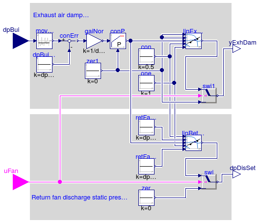
Information
Setpoint for return fan discharge pressure and exhaust air damper
for a multi zone VAV AHU according to ASHRAE guideline G36,
PART5.N.10 (return fan control with direct building pressure).
-
Return fan operates whenever associated supply fan is proven on and is
off otherwise.
-
Return fan is controlled to maintain return fan discharge static pressure
at setpoint dpBuiSet.
-
Exhaust damper is only enabled when the associated supply and return
fans are proven on (uFan=true) and the minimum outdoor air damper is open
(to be controlled in a separate sequence).
The exhaust dampers is closed when the fan is disabled.
-
The building static pressure is time averaged with a sliding 5-minute window
to dampen fluctuations. The averaged value shall be displayed and is used
for control.
-
When the exhaust damper is enabled, a control loop modulates the exhaust damper
in sequence with the return fan static pressure setpoint as shown in the figure
below to maintain the building pressure equal to dpBuiSet,
which is by default 12 Pa (0.05 inches).
The output signal of the building pressure control is as follows:
-
From 0 to 0.5, the building pressure control loop modulates the exhaust
dampers from
yExhDam = 0 (closed) to yExhDam = 1 (open).
-
From 0.5 to 1, the building pressure control loop resets the return fan
discharge static pressure setpoint from
dpDisMin
to dpDisMax. The dpDisMin and
dpDisMax are specified in Section G36 PART 3.2A.3.b.

Parameters
| Type | Name | Default | Description |
|---|
| PressureDifference | dpBuiSet | 12 | Building static pressure difference relative to ambient (positive to pressurize the building) [Pa] |
| PressureDifference | dpDisMin | 2.4 | Minimum return fan discharge static pressure difference setpoint [Pa] |
| PressureDifference | dpDisMax | 40 | Maximum return fan discharge static pressure setpoint [Pa] |
| Real | k | 1 | Gain, normalized using dpBuiSet [1] |
Connectors
| Type | Name | Description |
|---|
| input RealInput | dpBui | Building static pressure difference, relative to ambient (positive if pressurized) [Pa] |
| input BooleanInput | uFan | Fan on/off signal, true if fan is on |
| output RealOutput | dpDisSet | Return fan discharge static pressure setpoint [Pa] |
| output RealOutput | yExhDam | Exhaust damper control signal (0: closed, 1: open) [1] |
Modelica definition
block ReturnFanDirectPressure
parameter Modelica.SIunits.PressureDifference dpBuiSet(
displayUnit="Pa",
max=30) = 12 ;
parameter Modelica.SIunits.PressureDifference dpDisMin(
displayUnit="Pa",
final min=0,
final max=1000) = 2.4 ;
parameter Modelica.SIunits.PressureDifference dpDisMax(
displayUnit="Pa",
final min=0,
final max=1000) = 40 ;
parameter Real k(
final unit="1") = 1 ;
Buildings.Controls.OBC.CDL.Interfaces.RealInput dpBui(
final unit="Pa",
displayUnit="Pa") ;
Buildings.Controls.OBC.CDL.Interfaces.BooleanInput uFan ;
Buildings.Controls.OBC.CDL.Interfaces.RealOutput dpDisSet(
final unit="Pa",
displayUnit="Pa",
min=0) ;
Buildings.Controls.OBC.CDL.Interfaces.RealOutput yExhDam(
final unit="1",
min=0,
max=1) ;
Buildings.Controls.OBC.CDL.Continuous.Feedback conErr(
u1(
final unit="Pa", displayUnit="Pa"),
u2(
final unit="Pa", displayUnit="Pa"),
y(
final unit="Pa", displayUnit="Pa")) ;
Buildings.Controls.OBC.CDL.Continuous.MovingMean movMea(delta=300) ;
Buildings.Controls.OBC.CDL.Continuous.LimPID conP(
final controllerType=Buildings.Controls.OBC.CDL.Types.SimpleController.P,
final k=k,
yMax=1,
yMin=0) ;
Buildings.Controls.OBC.CDL.Continuous.Line linExhAirDam ;
Buildings.Controls.OBC.CDL.Continuous.Line linRetFanStaPre ;
Buildings.Controls.OBC.CDL.Logical.Switch swi1 ;
Buildings.Controls.OBC.CDL.Logical.Switch swi ;
protected
Buildings.Controls.OBC.CDL.Continuous.Sources.Constant dpBuiSetPoi(
final k=
dpBuiSet) ;
Buildings.Controls.OBC.CDL.Continuous.Sources.Constant retFanDisPreMin(
final
k=dpDisMin) ;
Buildings.Controls.OBC.CDL.Continuous.Sources.Constant retFanDisPreMax(
final
k=dpDisMax) ;
Buildings.Controls.OBC.CDL.Continuous.Sources.Constant zer(
final k=0) ;
Buildings.Controls.OBC.CDL.Continuous.Sources.Constant zer1(
final k=0) ;
Buildings.Controls.OBC.CDL.Continuous.Sources.Constant con(
final k=0.5) ;
Buildings.Controls.OBC.CDL.Continuous.Sources.Constant one(
final k=1) ;
Buildings.Controls.OBC.CDL.Continuous.Gain gaiNor(
final k=1/dpBuiSet) ;
equation
connect(movMea.u, dpBui);
connect(swi.u2, uFan);
connect(swi.u3, zer.y);
connect(zer1.y, linExhAirDam.x1);
connect(zer1.y, linExhAirDam.f1);
connect(con.y, linExhAirDam.x2);
connect(one.y, linExhAirDam.f2);
connect(con.y, linRetFanStaPre.x1);
connect(one.y, linRetFanStaPre.x2);
connect(retFanDisPreMin.y, linRetFanStaPre.f1);
connect(retFanDisPreMax.y, linRetFanStaPre.f2);
connect(linRetFanStaPre.y, swi.u1);
connect(uFan, swi1.u2);
connect(linExhAirDam.y, swi1.u1);
connect(swi1.y, yExhDam);
connect(zer1.y, swi1.u3);
connect(swi.y, dpDisSet);
connect(conP.y, linExhAirDam.u);
connect(conP.y, linRetFanStaPre.u);
connect(movMea.y, conErr.u1);
connect(dpBuiSetPoi.y, conErr.u2);
connect(conErr.y, gaiNor.u);
connect(gaiNor.y, conP.u_s);
connect(conP.u_m, zer1.y);
end ReturnFanDirectPressure;
Block to control multi zone VAV AHU supply fan
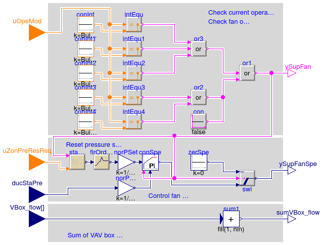
Information
Supply fan control for a multi zone VAV AHU according to
ASHRAE guideline G36, PART5.N.1 (Supply fan control).
a. Supply fan start/stop
- Supply fan shall run when system is in the Cool-down, Setup, or Occupied mode
- If there are any VAV-reheat boxes on perimeter zones, supply fan shall also
run when system is in Setback or Warmup mode;
- If the AHU does not serve dual duct boxes (
have_duaDucBox=true) or the AHU
does not have airflow measurement station (have_airFloMeaSta=false),
sum the current airflow rate from the VAV boxes and output to a software point.
b. Static pressure setpoint reset
Static pressure setpoint shall be reset using trim-respond logic using following
parameters as a starting point:
| Variable | Value | Definition |
|---|
| Device | AHU Supply Fan | Associated device |
| SP0 | 120 Pa (0.5 inches) | Initial setpoint |
| SPmin | 25 Pa (0.1 inches) | Minimum setpoint |
| SPmax | maxSet | Maximum setpoint |
| Td | 10 minutes | Delay timer |
| T | 2 minutes | Time step |
| I | 2 | Number of ignored requests |
| R | Zone static pressure reset requests | Number of requests |
| SPtrim | -12 Pa (-0.05 inches) | Trim amount |
| SPres | 15 Pa (+0.06 inches) | Respond amount |
| SPres_max | 32 Pa (+0.13 inches) | Maximum response per time interval |
c. Static pressure control
Supply fan speed is controlled with a PI controller to maintain duct static pressure at setpoint
when the fan is proven on. The setpoint for the PI controller and the measured
duct static pressure are normalized with the maximum design static presssure
maxSet.
Where the zone groups served by the system are small,
provide multiple sets of gains that are used in the control loop as a function
of a load indicator (such as supply fan airflow rate, the area of the zone groups
that are occupied, etc.).
Parameters
| Type | Name | Default | Description |
|---|
| System configuration |
| Integer | numZon | | Total number of served VAV boxes |
| Boolean | have_perZonRehBox | false | Check if there is any VAV-reheat boxes on perimeter zones |
| Boolean | have_duaDucBox | false | Check if the AHU serves dual duct boxes |
| Boolean | have_airFloMeaSta | false | Check if the AHU has AFMS (Airflow measurement station) |
| Trim and respond for pressure setpoint |
| PressureDifference | iniSet | 120 | Initial setpoint [Pa] |
| PressureDifference | minSet | 25 | Minimum setpoint [Pa] |
| PressureDifference | maxSet | | Maximum setpoint [Pa] |
| Time | delTim | 600 | Delay time after which trim and respond is activated [s] |
| Time | samplePeriod | 120 | Sample period [s] |
| Integer | numIgnReq | 2 | Number of ignored requests |
| PressureDifference | triAmo | -12.0 | Trim amount [Pa] |
| PressureDifference | resAmo | 15 | Respond amount (must be opposite in to triAmo) [Pa] |
| PressureDifference | maxRes | 32 | Maximum response per time interval (same sign as resAmo) [Pa] |
| Fan PID controller |
| SimpleController | controllerType | Buildings.Controls.OBC.CDL.T... | Type of controller |
| Real | k | 0.1 | Gain of controller, normalized using maxSet [1] |
| Time | Ti | 60 | Time constant of integrator block [s] |
| Time | Td | 0.1 | Time constant of derivative block [s] |
| Real | yFanMax | 1 | Maximum allowed fan speed [1] |
| Real | yFanMin | 0.1 | Lowest allowed fan speed if fan is on [1] |
Connectors
| Type | Name | Description |
|---|
| input IntegerInput | uOpeMod | System operation mode |
| input RealInput | ducStaPre | Measured duct static pressure [Pa] |
| input RealInput | VBox_flow[numZon] | VAV box airflow rate [m3/s] |
| input IntegerInput | uZonPreResReq | Zone static pressure reset requests |
| output BooleanOutput | ySupFan | Supply fan on status |
| output RealOutput | ySupFanSpe | Supply fan speed [1] |
| output RealOutput | sumVBox_flow | Sum of current airflow rates from VAV boxes [m3/s] |
Modelica definition
block VAVSupplyFan
parameter Integer numZon(min=2) ;
parameter Boolean have_perZonRehBox=false ;
parameter Boolean have_duaDucBox=false ;
parameter Boolean have_airFloMeaSta=false ;
parameter Modelica.SIunits.PressureDifference iniSet(displayUnit="Pa") = 120 ;
parameter Modelica.SIunits.PressureDifference minSet(displayUnit="Pa") = 25 ;
parameter Modelica.SIunits.PressureDifference maxSet(displayUnit="Pa") ;
parameter Modelica.SIunits.Time delTim=600 ;
parameter Modelica.SIunits.Time samplePeriod=120 ;
parameter Integer numIgnReq=2 ;
parameter Modelica.SIunits.PressureDifference triAmo(displayUnit="Pa") = -12.0
;
parameter Modelica.SIunits.PressureDifference resAmo(displayUnit="Pa") = 15 ;
parameter Modelica.SIunits.PressureDifference maxRes(displayUnit="Pa") = 32 ;
parameter Buildings.Controls.OBC.CDL.Types.SimpleController controllerType=
Buildings.Controls.OBC.CDL.Types.SimpleController.PI ;
parameter Real k(
final unit="1") = 0.1 ;
parameter Modelica.SIunits.Time Ti(min=0) = 60 ;
parameter Modelica.SIunits.Time Td(min=0) = 0.1 ;
parameter Real yFanMax(
min=0.1,
max=1,
unit="1") = 1 ;
parameter Real yFanMin(
min=0.1,
max=1,
unit="1") = 0.1 ;
Buildings.Controls.OBC.CDL.Interfaces.IntegerInput uOpeMod ;
Buildings.Controls.OBC.CDL.Interfaces.RealInput ducStaPre(
final unit="Pa",
quantity="PressureDifference") ;
Buildings.Controls.OBC.CDL.Interfaces.RealInput VBox_flow[numZon](
final unit="m3/s",
quantity="VolumeFlowRate")
if not (have_duaDucBox
or have_airFloMeaSta) ;
Buildings.Controls.OBC.CDL.Interfaces.IntegerInput uZonPreResReq ;
Buildings.Controls.OBC.CDL.Interfaces.BooleanOutput ySupFan ;
Buildings.Controls.OBC.CDL.Interfaces.RealOutput ySupFanSpe(
min=0,
max=1,
final unit="1") ;
Buildings.Controls.OBC.CDL.Interfaces.RealOutput sumVBox_flow(
final unit="m3/s",
quantity="VolumeFlowRate")
if not (have_duaDucBox
or have_airFloMeaSta) ;
Buildings.Controls.OBC.ASHRAE.G36_PR1.Generic.SetPoints.TrimAndRespond
staPreSetRes(
final iniSet=iniSet,
final minSet=minSet,
final maxSet=maxSet,
final delTim=delTim,
final samplePeriod=samplePeriod,
final numIgnReq=numIgnReq,
final triAmo=triAmo,
final resAmo=resAmo,
final maxRes=maxRes) ;
Buildings.Controls.OBC.CDL.Continuous.LimPID conSpe(
final controllerType=controllerType,
final k=k,
final Ti=Ti,
final Td=Td,
final yMax=yFanMax,
final yMin=yFanMin,
reset=Buildings.Controls.OBC.CDL.Types.Reset.Parameter,
y_reset=yFanMin) ;
protected
Buildings.Controls.OBC.CDL.Continuous.Sources.Constant zerSpe(k=0) ;
Buildings.Controls.OBC.CDL.Logical.Switch swi ;
Buildings.Controls.OBC.CDL.Continuous.MultiSum sum1(
final nin=numZon)
if not (
have_duaDucBox
or have_airFloMeaSta) ;
Buildings.Controls.OBC.CDL.Logical.Or or1 ;
Buildings.Controls.OBC.CDL.Logical.Or or2
if have_perZonRehBox ;
Buildings.Controls.OBC.CDL.Logical.Or3 or3 ;
Buildings.Controls.OBC.CDL.Logical.Sources.Constant con(k=false)
if not
have_perZonRehBox ;
Buildings.Controls.OBC.CDL.Integers.Sources.Constant conInt(k=Buildings.Controls.OBC.ASHRAE.G36_PR1.Types.OperationModes.coolDown)
;
Buildings.Controls.OBC.CDL.Integers.Sources.Constant conInt4(k=Buildings.Controls.OBC.ASHRAE.G36_PR1.Types.OperationModes.warmUp)
;
Buildings.Controls.OBC.CDL.Integers.Sources.Constant conInt1(k=Buildings.Controls.OBC.ASHRAE.G36_PR1.Types.OperationModes.setUp)
;
Buildings.Controls.OBC.CDL.Integers.Sources.Constant conInt2(k=Buildings.Controls.OBC.ASHRAE.G36_PR1.Types.OperationModes.occupied)
;
Buildings.Controls.OBC.CDL.Integers.Sources.Constant conInt3(k=Buildings.Controls.OBC.ASHRAE.G36_PR1.Types.OperationModes.setBack)
;
Buildings.Controls.OBC.CDL.Integers.Equal intEqu ;
Buildings.Controls.OBC.CDL.Integers.Equal intEqu1 ;
Buildings.Controls.OBC.CDL.Integers.Equal intEqu2 ;
Buildings.Controls.OBC.CDL.Integers.Equal intEqu3 ;
Buildings.Controls.OBC.CDL.Integers.Equal intEqu4 ;
CDL.Continuous.Gain norPSet(
final k=1/maxSet) ;
CDL.Continuous.Gain norPMea(
final k=1/maxSet) ;
CDL.Discrete.FirstOrderHold firOrdHol(
final samplePeriod=samplePeriod) ;
equation
connect(or2.y, or1.u2);
connect(or1.y, ySupFan);
connect(VBox_flow, sum1.u);
connect(sum1.y, sumVBox_flow);
connect(or1.y, staPreSetRes.uDevSta);
connect(or1.y, swi.u2);
connect(conSpe.y, swi.u1);
connect(zerSpe.y, swi.u3);
connect(swi.y, ySupFanSpe);
connect(uZonPreResReq, staPreSetRes.numOfReq);
connect(con.y, or1.u2);
connect(intEqu.y, or3.u1);
connect(intEqu2.y, or3.u3);
connect(intEqu1.y, or3.u2);
connect(conInt.y, intEqu.u2);
connect(conInt1.y, intEqu1.u2);
connect(conInt2.y, intEqu2.u2);
connect(conInt3.y, intEqu3.u2);
connect(conInt4.y, intEqu4.u2);
connect(uOpeMod, intEqu.u1);
connect(uOpeMod, intEqu1.u1);
connect(uOpeMod, intEqu2.u1);
connect(uOpeMod, intEqu3.u1);
connect(uOpeMod, intEqu4.u1);
connect(or3.y, or1.u1);
connect(intEqu3.y, or2.u1);
connect(intEqu4.y, or2.u2);
connect(norPSet.y, conSpe.u_s);
connect(ducStaPre, norPMea.u);
connect(norPMea.y, conSpe.u_m);
connect(norPSet.u, firOrdHol.y);
connect(staPreSetRes.y, firOrdHol.u);
connect(conSpe.trigger, or1.y);
end VAVSupplyFan;
Multizone VAV AHU coil valve positions
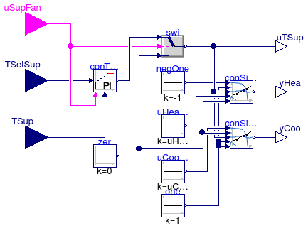
Information
Block that outputs the coil valve postions for VAV system with multiple zones,
implemented according to the ASHRAE Guideline G36, PART5.N.2
(Supply air temperature control).
The block also outputs the supply air temperature control signal
which is used to control the economizer if present.
Valves control
Supply air temperature shall be controlled to setpoint using a control loop whose
output is mapped to sequence the hot water valve (or modulating electric heating
coil if applicable) and chilled water valve.
Parameters
| Type | Name | Default | Description |
|---|
| SimpleController | controllerType | Buildings.Controls.OBC.CDL.T... | Type of controller for supply air temperature signal |
| Real | kTSup | 0.05 | Gain of controller for supply air temperature signal [1/K] |
| Time | TiTSup | 600 | Time constant of integrator block for supply temperature control signal [s] |
| Time | TdTSup | 0.1 | Time constant of derivative block for supply temperature control signal [s] |
| Real | uHeaMax | -0.25 | Upper limit of controller signal when heating coil is off. Require -1 < uHeaMax < uCooMin < 1. |
| Real | uCooMin | 0.25 | Lower limit of controller signal when cooling coil is off. Require -1 < uHeaMax < uCooMin < 1. |
Connectors
| Type | Name | Description |
|---|
| input RealInput | TSup | Measured supply air temperature [K] |
| input RealInput | TSetSup | Setpoint for supply air temperature [K] |
| input BooleanInput | uSupFan | Supply fan status |
| output RealOutput | yHea | Control signal for heating [1] |
| output RealOutput | yCoo | Control signal for cooling [1] |
| output RealOutput | uTSup | Supply temperature control signal [1] |
Modelica definition
block VAVSupplySignals
parameter Buildings.Controls.OBC.CDL.Types.SimpleController controllerType=
Buildings.Controls.OBC.CDL.Types.SimpleController.PI ;
parameter Real kTSup(
final unit="1/K") = 0.05 ;
parameter Modelica.SIunits.Time TiTSup=600 ;
parameter Modelica.SIunits.Time TdTSup=0.1 ;
parameter Real uHeaMax(min=-0.9) = -0.25 ;
parameter Real uCooMin(max=0.9) = 0.25 ;
Buildings.Controls.OBC.CDL.Interfaces.RealInput TSup(
final unit="K",
final
quantity="ThermodynamicTemperature") ;
Buildings.Controls.OBC.CDL.Interfaces.RealInput TSetSup(
final unit="K",
final quantity="ThermodynamicTemperature") ;
Buildings.Controls.OBC.CDL.Interfaces.BooleanInput uSupFan ;
Buildings.Controls.OBC.CDL.Interfaces.RealOutput yHea(
final min=0,
final max=1,
final unit="1") ;
Buildings.Controls.OBC.CDL.Interfaces.RealOutput yCoo(
final min=0,
final max=1,
final unit="1") ;
Buildings.Controls.OBC.CDL.Interfaces.RealOutput uTSup(
final max=1,
final unit="1",
final min=-1) ;
protected
Buildings.Controls.OBC.CDL.Continuous.LimPID conTSup(
final controllerType=controllerType,
final k=kTSup,
final Ti=TiTSup,
final Td=TdTSup,
final yMax=1,
final yMin=-1,
final y_reset=0,
final reverseAction=true,
final reset=Buildings.Controls.OBC.CDL.Types.Reset.Parameter) ;
Buildings.Controls.OBC.CDL.Logical.Switch swi;
Buildings.Controls.OBC.CDL.Continuous.Sources.Constant uHeaMaxCon(
final k=
uHeaMax) ;
Buildings.Controls.OBC.CDL.Continuous.Sources.Constant negOne(
final k=-1) ;
Buildings.Controls.OBC.CDL.Continuous.Sources.Constant uCooMinCon(
final k=
uCooMin) ;
Buildings.Controls.OBC.CDL.Continuous.Sources.Constant zer(
final k=0) ;
Buildings.Controls.OBC.CDL.Continuous.Sources.Constant one(
final k=1) ;
Buildings.Controls.OBC.CDL.Continuous.Line conSigCoo(
final limitBelow=true,
final limitAbove=false) ;
Buildings.Controls.OBC.CDL.Continuous.Line conSigHea(
final limitBelow=false,
final limitAbove=true) ;
equation
connect(zer.y, swi.u3);
connect(TSup, conTSup.u_m);
connect(negOne.y, conSigHea.x1);
connect(one.y, conSigHea.f1);
connect(swi.y, conSigHea.u);
connect(swi.y, conSigCoo.u);
connect(uHeaMaxCon.y, conSigHea.x2);
connect(zer.y, conSigHea.f2);
connect(uCooMinCon.y, conSigCoo.x1);
connect(zer.y, conSigCoo.f1);
connect(one.y, conSigCoo.x2);
connect(one.y, conSigCoo.f2);
connect(conSigHea.y, yHea);
connect(conSigCoo.y, yCoo);
connect(swi.y, uTSup);
connect(TSetSup, conTSup.u_s);
connect(uSupFan, swi.u2);
connect(conTSup.y, swi.u1);
connect(uSupFan, conTSup.trigger);
end VAVSupplySignals;
Supply air temperature setpoint for multi zone system
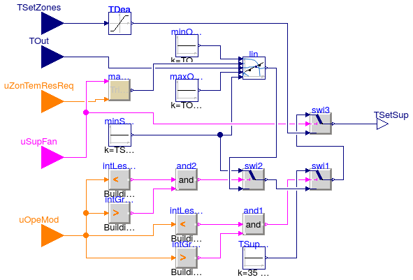
Information
Block that outputs the supply air temperature setpoint and the coil valve control
inputs for VAV system with multiple zones, implemented according to the ASHRAE
Guideline G36, PART5.N.2 (Supply air temperature control).
The control loop is enabled when the supply air fan uSupFan is proven on,
and disabled and the output set to Deadband otherwise.
The supply air temperature setpoint is computed as follows.
Setpoints for TSupMin, TSupMax,
TSupDes, TOutMin, TOutMax
The default range of outdoor air temperature (TOutMin=16°C,
TOutMax=21°C) used to reset the occupied mode TSetSup
was chosen to maximize economizer hours. It may be preferable to use a lower
range of outdoor air temperature (e.g. TOutMin=13°C,
TOutMax=18°C) to minimize fan energy.
The TSupMin variable is used during warm weather when little reheat
is expected to minimize fan energy. It should not be set too low or it may cause
excessive chilled water temperature reset requests which will reduce chiller
plant efficiency. It should be set no lower than the design coil leaving air
temperature.
The TSupMax variable is typically 18 °C in mild and dry climate,
16 °C or lower in humid climates. It should not typically be greater than
18 °C since this may lead to excessive fan energy that can offset the mechanical
cooling savings from economizer operation.
During occupied mode (opeMod=1)
The TSetSup shall be reset from TSupMin when the outdoor
air temperature is TOutMax and above, proportionally up to
TMax when the outdoor air temperature is TOutMin and
below. The TMax shall be reset using trim and respond logic between
TSupDes and TSupMax. Parameters suggested for the
trim and respond logic are shown in the table below. They require adjustment
during the commissioning and tuning phase.
| Variable | Value | Definition |
|---|
| Device | AHU Supply Fan | Associated device |
| SP0 | SPmax | Initial setpoint |
| SPmin | TSupDes | Minimum setpoint |
| SPmax | TSupMax | Maximum setpoint |
| Td | 10 minutes | Delay timer |
| T | 2 minutes | Time step |
| I | 2 | Number of ignored requests |
| R | Zone cooling requests | Number of requests |
| SPtrim | +0.1°C | Trim amount |
| SPres | -0.2°C | Respond amount |
| SPres_max | -0.6°C | Maximum response per time interval |

During Setup and Cool-down modes (opeMod=2, opeMod=3)
Supply air temperature setpoint TSetSup shall be TSupMin.
During Setback and Warmup modes (opeMod=4, opeMod=5)
Supply air temperature setpoint TSetSup shall be 35°C.
Valves control
Supply air temperature shall be controlled to setpoint using a control loop whose
output is mapped to sequence the hot water valve or modulating electric heating
coil (if applicable) or chilled water valves.
Parameters
| Type | Name | Default | Description |
|---|
| Temperatures |
| Temperature | TSupMin | 285.15 | Lowest cooling supply air temperature setpoint [K] |
| Temperature | TSupMax | 291.15 | Highest cooling supply air temperature setpoint. It is typically 18 degC (65 degF) in mild and dry climates, 16 degC (60 degF) or lower in humid climates [K] |
| Temperature | TSupDes | 286.15 | Nominal supply air temperature setpoint [K] |
| Temperature | TOutMin | 289.15 | Lower value of the outdoor air temperature reset range. Typically value is 16 degC (60 degF) [K] |
| Temperature | TOutMax | 294.15 | Higher value of the outdoor air temperature reset range. Typically value is 21 degC (70 degF) [K] |
| Trim and respond logic |
| Temperature | iniSet | maxSet | Initial setpoint [K] |
| Temperature | maxSet | TSupMax | Maximum setpoint [K] |
| Temperature | minSet | TSupDes | Minimum setpoint [K] |
| Time | delTim | 600 | Delay timer [s] |
| Time | samplePeriod | 120 | Sample period of component [s] |
| Integer | numIgnReq | 2 | Number of ignorable requests for TrimResponse logic |
| TemperatureDifference | triAmo | 0.1 | Trim amount [K] |
| TemperatureDifference | resAmo | -0.2 | Response amount [K] |
| TemperatureDifference | maxRes | -0.6 | Maximum response per time interval [K] |
Connectors
| Type | Name | Description |
|---|
| input RealInput | TOut | Outdoor air temperature [K] |
| input RealInput | TSetZones | Average of heating and cooling setpoint [K] |
| input BooleanInput | uSupFan | Supply fan status |
| input IntegerInput | uOpeMod | System operation mode |
| input IntegerInput | uZonTemResReq | Zone cooling supply air temperature reset request |
| output RealOutput | TSetSup | Setpoint for supply air temperature [K] |
Modelica definition
block VAVSupplyTemperature
parameter Modelica.SIunits.Temperature TSupMin=285.15 ;
parameter Modelica.SIunits.Temperature TSupMax=291.15 ;
parameter Modelica.SIunits.Temperature TSupDes=286.15 ;
parameter Modelica.SIunits.Temperature TOutMin=289.15 ;
parameter Modelica.SIunits.Temperature TOutMax=294.15 ;
parameter Modelica.SIunits.Temperature iniSet=maxSet ;
parameter Modelica.SIunits.Temperature maxSet=TSupMax ;
parameter Modelica.SIunits.Temperature minSet=TSupDes ;
parameter Modelica.SIunits.Time delTim=600 ;
parameter Modelica.SIunits.Time samplePeriod(min=1E-3) = 120 ;
parameter Integer numIgnReq=2 ;
parameter Modelica.SIunits.TemperatureDifference triAmo=0.1 ;
parameter Modelica.SIunits.TemperatureDifference resAmo=-0.2 ;
parameter Modelica.SIunits.TemperatureDifference maxRes=-0.6 ;
Buildings.Controls.OBC.CDL.Interfaces.RealInput TOut(
final unit="K", quantity
="ThermodynamicTemperature") ;
Buildings.Controls.OBC.CDL.Interfaces.RealInput TSetZones(
final unit="K",
quantity="ThermodynamicTemperature") ;
Buildings.Controls.OBC.CDL.Interfaces.BooleanInput uSupFan ;
Buildings.Controls.OBC.CDL.Interfaces.IntegerInput uOpeMod ;
Buildings.Controls.OBC.CDL.Interfaces.IntegerInput uZonTemResReq ;
Buildings.Controls.OBC.CDL.Interfaces.RealOutput TSetSup(
final unit="K",
quantity="ThermodynamicTemperature") ;
Buildings.Controls.OBC.ASHRAE.G36_PR1.Generic.SetPoints.TrimAndRespond
maxSupTemRes(
final delTim=delTim,
final iniSet=iniSet,
final minSet=minSet,
final maxSet=maxSet,
final samplePeriod=samplePeriod,
final numIgnReq=numIgnReq,
final triAmo=triAmo,
final resAmo=resAmo,
final maxRes=maxRes) ;
protected
Buildings.Controls.OBC.CDL.Continuous.Line lin ;
Buildings.Controls.OBC.CDL.Continuous.Sources.Constant minOutTem(k=TOutMin) ;
Buildings.Controls.OBC.CDL.Continuous.Sources.Constant maxOutTem(k=TOutMax) ;
Buildings.Controls.OBC.CDL.Continuous.Sources.Constant minSupTem(k=TSupMin) ;
Buildings.Controls.OBC.CDL.Logical.And and2 ;
Buildings.Controls.OBC.CDL.Logical.And and1 ;
Buildings.Controls.OBC.CDL.Continuous.Sources.Constant TSupWarUpSetBac(k=35 +
273.15) ;
Buildings.Controls.OBC.CDL.Logical.Switch swi1 ;
Buildings.Controls.OBC.CDL.Logical.Switch swi2 ;
Buildings.Controls.OBC.CDL.Continuous.Limiter TDea(uMax=24 + 273.15, uMin=21 +
273.15) ;
Buildings.Controls.OBC.CDL.Logical.Switch swi3 ;
Buildings.Controls.OBC.CDL.Integers.LessThreshold intLesThr(threshold=
Buildings.Controls.OBC.ASHRAE.G36_PR1.Types.OperationModes.warmUp) ;
Buildings.Controls.OBC.CDL.Integers.GreaterThreshold intGreThr(threshold=
Buildings.Controls.OBC.ASHRAE.G36_PR1.Types.OperationModes.occupied) ;
Buildings.Controls.OBC.CDL.Integers.LessThreshold intLesThr1(threshold=
Buildings.Controls.OBC.ASHRAE.G36_PR1.Types.OperationModes.unoccupied) ;
Buildings.Controls.OBC.CDL.Integers.GreaterThreshold intGreThr1(threshold=
Buildings.Controls.OBC.ASHRAE.G36_PR1.Types.OperationModes.setUp) ;
equation
connect(minOutTem.y, lin.x1);
connect(TOut, lin.u);
connect(maxOutTem.y, lin.x2);
connect(minSupTem.y, lin.f2);
connect(and1.y, swi1.u2);
connect(TSupWarUpSetBac.y, swi1.u1);
connect(and2.y, swi2.u2);
connect(minSupTem.y, swi2.u1);
connect(swi2.y, swi1.u3);
connect(TSetZones, TDea.u);
connect(uSupFan, swi3.u2);
connect(swi1.y, swi3.u1);
connect(TDea.y, swi3.u3);
connect(intLesThr1.y, and1.u1);
connect(intGreThr1.y, and1.u2);
connect(intLesThr.y, and2.u1);
connect(intGreThr.y, and2.u2);
connect(uOpeMod, intLesThr.u);
connect(uOpeMod, intGreThr.u);
connect(uOpeMod, intLesThr1.u);
connect(uOpeMod, intGreThr1.u);
connect(lin.y, swi2.u3);
connect(uZonTemResReq, maxSupTemRes.numOfReq);
connect(uSupFan, maxSupTemRes.uDevSta);
connect(maxSupTemRes.y, lin.f1);
connect(swi3.y, TSetSup);
end VAVSupplyTemperature;
 Buildings.Controls.OBC.ASHRAE.G36_PR1.AHUs.MultiZone.SetPoints.ExhaustDamper
 Buildings.Controls.OBC.ASHRAE.G36_PR1.AHUs.MultiZone.SetPoints.OutsideAirFlow
 Buildings.Controls.OBC.ASHRAE.G36_PR1.AHUs.MultiZone.SetPoints.ReturnFanDirectPressure
 Buildings.Controls.OBC.ASHRAE.G36_PR1.AHUs.MultiZone.SetPoints.VAVSupplyFan
 Buildings.Controls.OBC.ASHRAE.G36_PR1.AHUs.MultiZone.SetPoints.VAVSupplySignals
 Buildings.Controls.OBC.ASHRAE.G36_PR1.AHUs.MultiZone.SetPoints.VAVSupplyTemperature