Buildings.Controls.Continuous.Examples
Collection of models that illustrate model use and test models
Information
This package contains examples for the use of models that can be found in Buildings.Controls.Continuous.
Extends from Modelica.Icons.ExamplesPackage (Icon for packages containing runnable examples).
Package Content
| Name | Description |
|---|---|
| Test model for PID controller with optional reverse action | |
| Example that demonstrates the controller output reset | |
| Example model for block that outputs the number of requests | |
| Example model for off timer | |
| Example model for PID controller with hysteresis | |
| Example model for PID controller with hysteresis and timer | |
| Example model for signal ranker |
 Buildings.Controls.Continuous.Examples.LimPID
Test model for PID controller with optional reverse action
Information
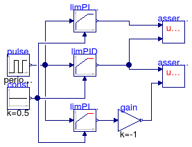
This model tests the implementation of the
PID controller with optional reverse action.
The model limPIDOri is the original
implementation of the controller from the Modelica
Standard Library. The models limPID
and limPIDRev are the implementations
from the Buildings library. The model
limPIDRev is parameterized to have
reverse action.
The assertion blocks test whether the results
of all three controllers are identical.
Extends from Modelica.Icons.Example (Icon for runnable examples).
Modelica definition
Buildings.Controls.Continuous.Examples.LimPIDWithReset
Example that demonstrates the controller output reset
Information
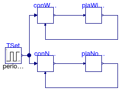
Example that demonstrates the effect of the integrator reset. The top model has the reset of the controller output enabled. By plotting the controller error, one sees that the integrator reset improves the closed loop performance slightly. Note, however, that both controllers have an integrator anti-windup and hence the integrator reset has limited benefits.
Extends from Modelica.Icons.Example (Icon for runnable examples).
Modelica definition
Buildings.Controls.Continuous.Examples.NumberOfRequests
Example model for block that outputs the number of requests
Information
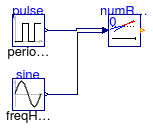
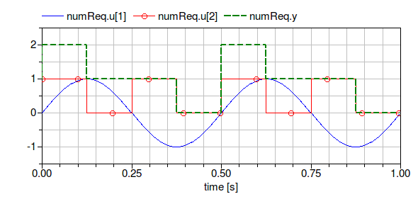
Example that demonstrates the use of the block Buildings.Controls.Continuous.NumberOfRequests. The parameters of the block are such that the output is incremented for each input signal that is strictly larger than 0. The figure below shows the inputs and the output of the block.
Extends from Modelica.Icons.Example (Icon for runnable examples).
Modelica definition
Buildings.Controls.Continuous.Examples.OffTimer
Example model for off timer
Information
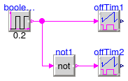
Example that demonstrates the use of the model
Buildings.Controls.Continuous.OffTimer.
The input to the two timers are alternating boolean values.
Whenever the input becomes false(=0), the timer is reset.
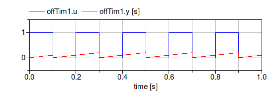
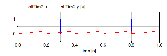
The figures below show the input and output of the blocks.
Extends from Modelica.Icons.Example (Icon for runnable examples).
Modelica definition
Buildings.Controls.Continuous.Examples.PIDHysteresis
Example model for PID controller with hysteresis
Information
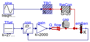
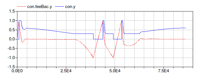
Example that demonstrates the use of the PID controller
with hysteresis. The control objective is to keep
the temperature of the energy storage cap
at 40°C.
The controller con is parameterized to
switch on if the control error is bigger than
eon=1.
The output of the controller remains above ymin=0.3 until the control
error is smaller than eoff=-1, at which
time the controller outputs y=0 until the
control error is again bigger than 1.
The figure below shows the control error
con.feeBac.y and the control signal
con.y.
Extends from Modelica.Icons.Example (Icon for runnable examples).
Modelica definition
Buildings.Controls.Continuous.Examples.PIDHysteresisTimer
Example model for PID controller with hysteresis and timer
Information
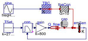
Example that demonstrates the use of the PID controller
with hysteresis and off timer.
The example is identical to
Buildings.Controls.Continuous.Examples.PIDHysteresis,
except that the controller also has an off timer.
This timer keeps the control signal at y=0
for a period of minOffTime=1000 seconds.
This may be used to avoid short-cycling if the load is small
and the system has little heat capacity.
The figure below shows the control error
con.feeBac.y and the control signal
con.y.

Extends from Modelica.Icons.Example (Icon for runnable examples).
Modelica definition
Buildings.Controls.Continuous.Examples.SignalRanker
Example model for signal ranker
Information
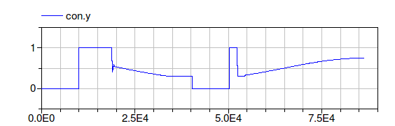
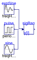
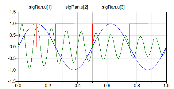
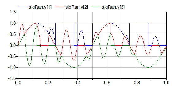
Example that demonstrates the use of the signal ranker model.
The figure below shows the input and output signals of the block.
Note that
sigRan.y[1] ≥ sigRan.y[2] ≥ sigRan.y[3].
Extends from Modelica.Icons.Example (Icon for runnable examples).
Modelica definition
 Buildings.Controls.Continuous.Examples.LimPIDWithReset.Plant
Plant model
Information
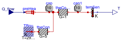
Plant model for Buildings.Controls.Continuous.Examples.LimPIDWithReset. consisting of a simple heat transfer model.
Implementation
To compare the effect of the controller output reset, the plant and control models have been implemented in separate blocks so they can be instantiated twice in the system model with the appropriate control settings.
Extends from Modelica.Blocks.Icons.Block (Basic graphical layout of input/output block).
Connectors
| Type | Name | Description |
|---|---|---|
| input RealInput | Q_flow | Heat flow rate added to system [W] |
| output RealOutput | T | Controlled temperature [K] |
Modelica definition
 Buildings.Controls.Continuous.Examples.LimPIDWithReset.Controller
PID controller with optional output reset
Information
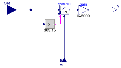
Controller model for Buildings.Controls.Continuous.Examples.LimPIDWithReset.
The controller is reset whenever the input signal becomes bigger than 30°C.
Implementation
To compare the effect of the controller output reset, the plant and control models have been implemented in separate blocks so they can be instantiated twice in the system model with the appropriate control settings.
Extends from Modelica.Blocks.Icons.Block (Basic graphical layout of input/output block).
Parameters
| Type | Name | Default | Description |
|---|---|---|---|
| Reset | reset | Buildings.Types.Reset.Disabled | Type of controller output reset |
Connectors
| Type | Name | Description |
|---|---|---|
| input RealInput | TSet | Temperature set point [K] |
| input RealInput | u_m | Measured temperature [K] |
| output RealOutput | y | Control signal |