Collection of models that illustrate model use and test models
Information
This package contains examples for the use of models that can be found in
Buildings.Fluid.FMI.Adaptors.
Extends from Modelica.Icons.ExamplesPackage (Icon for packages containing runnable examples).
Package Content
| Name |
Description |
 ThermalZoneHVACNoExhaust ThermalZoneHVACNoExhaust
|
Example of a thermal zone and an HVAC system both exposed using the FMI adaptor |
 ThermalZoneHVACWithExhaust ThermalZoneHVACWithExhaust
|
Example of a thermal zone and an HVAC system both exposed using the FMI adaptor |
Example of a thermal zone and an HVAC system both exposed using the FMI adaptor

Information
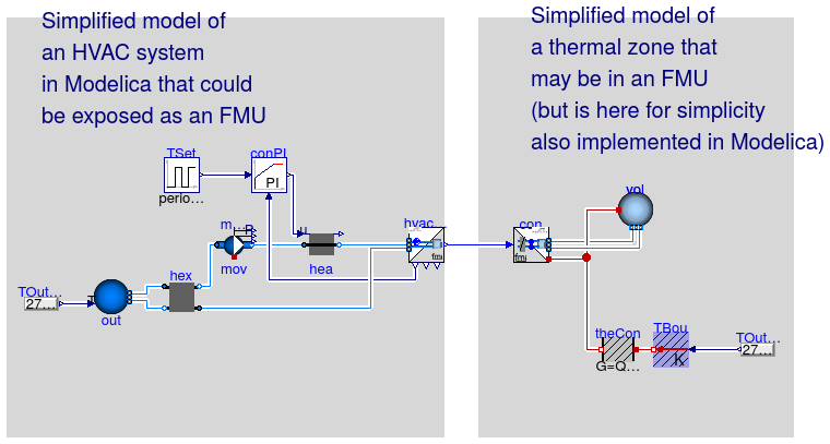
This example demonstrates how to
use the adaptors
Buildings.Fluid.FMI.Adaptors.HVAC
and
Buildings.Fluid.FMI.Adaptors.ThermalZone
On the left hand side is an HVAC system with supply and return air stream.
These are all connected to the adaptor.
On the right of the adaptor is a simple room model, approximated by a volume with
first order dynamics and heat loss to the ambient.
Note that the there is zero net air flow into and out of the volume vol
because the adaptor hvacAda conserves mass. Hence, any infiltration or
exfiltration needs to be
connected to the adaptor hvacAda, rather than the volume vol.
Extends from Modelica.Icons.Example (Icon for runnable examples).
Parameters
| Type | Name | Default | Description |
|---|
| replaceable package MediumA | Buildings.Media.Air | Medium for air |
| HeatFlowRate | Q_flow_nominal | 30*6*6 | Nominal heat loss of the room [W] |
| Volume | VRoo | 6*6*2.7 | Room volume [m3] |
| MassFlowRate | m_flow_nominal | VRoo*2*1.2/3600 | Nominal mass flow rate [kg/s] |
Connectors
| Type | Name | Description |
|---|
| replaceable package MediumA | Medium for air |
Modelica definition
model ThermalZoneHVACNoExhaust
extends Modelica.Icons.Example;
replaceable package MediumA =
Buildings.Media.Air ;
Buildings.Fluid.FMI.Adaptors.HVAC hvacAda(
redeclare final package Medium=
MediumA, nPorts=2)
;
parameter Modelica.SIunits.HeatFlowRate Q_flow_nominal = 30*6*6
;
parameter Modelica.SIunits.Volume VRoo = 6*6*2.7 ;
parameter Modelica.SIunits.MassFlowRate m_flow_nominal=VRoo*2*1.2/3600
;
Buildings.Fluid.FMI.Adaptors.ThermalZone con(
redeclare package Medium =
MediumA,
nPorts=2) ;
Modelica.Blocks.Sources.Pulse TSet(
amplitude=4,
period=86400,
offset=273.15 + 16,
startTime=7*3600) ;
Controls.Continuous.LimPID conPI(
controllerType=Modelica.Blocks.Types.SimpleController.PI,
k=1,
yMax=1,
yMin=0,
Ti=120) ;
Movers.FlowControlled_m_flow mov(
redeclare package Medium =
MediumA,
m_flow_nominal=m_flow_nominal,
addPowerToMedium=false,
nominalValuesDefineDefaultPressureCurve=true,
dp_nominal=1200,
inputType=Buildings.Fluid.Types.InputType.Constant,
energyDynamics=Modelica.Fluid.Types.Dynamics.SteadyState,
use_inputFilter=false) ;
HeatExchangers.HeaterCooler_u
hea(
redeclare package Medium =
MediumA,
m_flow_nominal=m_flow_nominal,
dp_nominal=1000,
Q_flow_nominal=Q_flow_nominal,
energyDynamics=Modelica.Fluid.Types.Dynamics.SteadyState) ;
Sources.Boundary_pT out(
redeclare package Medium =
MediumA,
nPorts=2,
use_T_in=true) ;
HeatExchangers.ConstantEffectiveness hex(
redeclare package Medium1 =
MediumA,
redeclare package Medium2 =
MediumA,
m1_flow_nominal=m_flow_nominal,
m2_flow_nominal=m_flow_nominal,
dp1_nominal=200,
dp2_nominal=200) ;
MixingVolumes.MixingVolume vol(
redeclare package Medium =
MediumA,
mSenFac=3,
m_flow_nominal=m_flow_nominal,
energyDynamics=Modelica.Fluid.Types.Dynamics.FixedInitial,
V=VRoo,
nPorts=2) ;
Modelica.Thermal.HeatTransfer.Components.ThermalConductor theCon(G=
Q_flow_nominal/20)
;
Buildings.HeatTransfer.Sources.PrescribedTemperature TBou
;
Modelica.Blocks.Sources.RealExpression TOutZon(
y=273.15 + 16 - 5*
cos(time/86400*2*Modelica.Constants.pi))
;
Modelica.Blocks.Sources.RealExpression TOutHVAC(
y=273.15 + 16 - 5*
cos(time/86400*2*Modelica.Constants.pi))
;
equation
connect(mov.port_b,hea. port_a);
connect(hex.port_b1,mov. port_a);
connect(out.ports[1],hex. port_b2);
connect(out.ports[2],hex. port_a1);
connect(conPI.y, hea.u);
connect(TBou.port,theCon. port_a);
connect(vol.heatPort, theCon.port_b);
connect(conPI.u_s, TSet.y);
connect(TOutZon.y, TBou.T);
connect(hvacAda.TAirZon[1], conPI.u_m);
connect(con.ports[1], vol.ports[1]);
connect(vol.heatPort, con.heaPorAir);
connect(con.ports[2], vol.ports[2]);
connect(hvacAda.fluPor, con.fluPor);
connect(hea.port_b, hvacAda.ports[1]);
connect(hvacAda.ports[2], hex.port_a2);
connect(TOutHVAC.y, out.T_in);
end ThermalZoneHVACNoExhaust;
Example of a thermal zone and an HVAC system both exposed using the FMI adaptor

Information
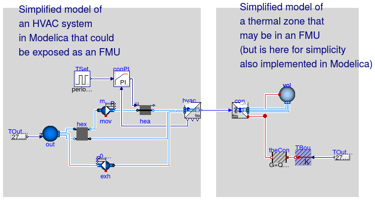
This example demonstrates how to
use the adaptors
Buildings.Fluid.FMI.Adaptors.HVAC
and
Buildings.Fluid.FMI.Adaptors.ThermalZone
It is identical to
Buildings.Fluid.FMI.Adaptors.Examples.ThermalZoneHVACNoExhaust
except that it adds a forced exhaust air stream.
Extends from Buildings.Fluid.FMI.Adaptors.Examples.ThermalZoneHVACNoExhaust (Example of a thermal zone and an HVAC system both exposed using the FMI adaptor).
Parameters
| Type | Name | Default | Description |
|---|
| replaceable package MediumA | Air | Medium for air |
| HeatFlowRate | Q_flow_nominal | 30*6*6 | Nominal heat loss of the room [W] |
| Volume | VRoo | 6*6*2.7 | Room volume [m3] |
| MassFlowRate | m_flow_nominal | VRoo*2*1.2/3600 | Nominal mass flow rate [kg/s] |
Modelica definition
model ThermalZoneHVACWithExhaust
extends Buildings.Fluid.FMI.Adaptors.Examples.ThermalZoneHVACNoExhaust(
hvacAda(nPorts=3),
out(nPorts=3),
con(nPorts=3),
vol(nPorts=3));
Movers.FlowControlled_m_flow exh(
redeclare package Medium =
MediumA,
addPowerToMedium=false,
nominalValuesDefineDefaultPressureCurve=true,
dp_nominal=1200,
inputType=Buildings.Fluid.Types.InputType.Constant,
energyDynamics=Modelica.Fluid.Types.Dynamics.SteadyState,
use_inputFilter=false,
m_flow_nominal=0.1*m_flow_nominal) ;
equation
connect(hvacAda.ports[3], exh.port_a);
connect(exh.port_b, out.ports[3]);
connect(con.ports[3], vol.ports[3]);
end ThermalZoneHVACWithExhaust;
 Buildings.Fluid.FMI.Adaptors.Examples.ThermalZoneHVACNoExhaust
 Buildings.Fluid.FMI.Adaptors.Examples.ThermalZoneHVACWithExhaust
