Buildings.Fluid.HeatExchangers
Package with heat exchanger models
Information
This package contains models for heat exchangers with and without humidity condensation.Extends from Modelica.Icons.VariantsPackage (Icon for package containing variants).
Package Content
| Name | Description |
|---|---|
| Heat exchanger with constant effectiveness | |
| Counterflow coil with discretization along the flow paths and without humidity condensation | |
| Coil with discretization along the flow paths and no humidity condensation | |
| Heat exchanger with effectiveness - NTU relation and no moisture condensation | |
| Evaporator or condenser with refrigerant experiencing constant temperature phase change | |
| Ideal heater or cooler with a prescribed outlet temperature | |
| Heater or cooler with prescribed heat flow rate | |
| Counterflow coil with discretization along the flow paths and humidity condensation | |
| Coil with discretization along the flow paths and humidity condensation | |
| Package with cooling tower models | |
| DX(Direct Expansion) cooling coil models | |
| Package with ground-coupled heat exchanger models | |
| Package with radiant slab models | |
| Package with radiators models for hydronic space heating systems | |
| Collection of models that illustrate model use and test models | |
| Collection of models that validate the heat exchanger models | |
| Package with base classes for Buildings.Fluid.HeatExchangers |
 Buildings.Fluid.HeatExchangers.ConstantEffectiveness
Heat exchanger with constant effectiveness

Information
Model for a heat exchanger with constant effectiveness.
This model transfers heat in the amount of
Q = Qmax ε,
where ε is a constant effectiveness and Qmax is the maximum heat that can be transferred.
For a heat and moisture exchanger, use Buildings.Fluid.MassExchangers.ConstantEffectiveness instead of this model.
Extends from Buildings.Fluid.HeatExchangers.BaseClasses.PartialEffectiveness (Partial model to implement heat exchangers based on effectiveness model).
Parameters
| Type | Name | Default | Description |
|---|---|---|---|
| replaceable package Medium1 | PartialMedium | Medium 1 in the component | |
| replaceable package Medium2 | PartialMedium | Medium 2 in the component | |
| HeatFlowRate | Q1_flow | eps*QMax_flow | Heat transferred into the medium 1 [W] |
| MassFlowRate | mWat1_flow | 0 | Moisture mass flow rate added to the medium 1 [kg/s] |
| HeatFlowRate | Q2_flow | -Q1_flow | Heat transferred into the medium 2 [W] |
| MassFlowRate | mWat2_flow | 0 | Moisture mass flow rate added to the medium 2 [kg/s] |
| Boolean | sensibleOnly1 | true | Set to true if sensible exchange only for medium 1 |
| Boolean | sensibleOnly2 | true | Set to true if sensible exchange only for medium 2 |
| Efficiency | eps | 0.8 | Heat exchanger effectiveness [1] |
| Nominal condition | |||
| MassFlowRate | m1_flow_nominal | Nominal mass flow rate [kg/s] | |
| MassFlowRate | m2_flow_nominal | Nominal mass flow rate [kg/s] | |
| PressureDifference | dp1_nominal | Pressure difference [Pa] | |
| PressureDifference | dp2_nominal | Pressure difference [Pa] | |
| Assumptions | |||
| Boolean | allowFlowReversal1 | true | = false to simplify equations, assuming, but not enforcing, no flow reversal for medium 1 |
| Boolean | allowFlowReversal2 | true | = false to simplify equations, assuming, but not enforcing, no flow reversal for medium 2 |
| Advanced | |||
| MassFlowRate | m1_flow_small | 1E-4*abs(m1_flow_nominal) | Small mass flow rate for regularization of zero flow [kg/s] |
| MassFlowRate | m2_flow_small | 1E-4*abs(m2_flow_nominal) | Small mass flow rate for regularization of zero flow [kg/s] |
| Boolean | homotopyInitialization | true | = true, use homotopy method |
| Diagnostics | |||
| Boolean | show_T | false | = true, if actual temperature at port is computed |
| Flow resistance | |||
| Medium 1 | |||
| Boolean | from_dp1 | false | = true, use m_flow = f(dp) else dp = f(m_flow) |
| Boolean | linearizeFlowResistance1 | false | = true, use linear relation between m_flow and dp for any flow rate |
| Real | deltaM1 | 0.1 | Fraction of nominal flow rate where flow transitions to laminar |
| Medium 2 | |||
| Boolean | from_dp2 | false | = true, use m_flow = f(dp) else dp = f(m_flow) |
| Boolean | linearizeFlowResistance2 | false | = true, use linear relation between m_flow and dp for any flow rate |
| Real | deltaM2 | 0.1 | Fraction of nominal flow rate where flow transitions to laminar |
Connectors
| Type | Name | Description |
|---|---|---|
| FluidPort_a | port_a1 | Fluid connector a1 (positive design flow direction is from port_a1 to port_b1) |
| FluidPort_b | port_b1 | Fluid connector b1 (positive design flow direction is from port_a1 to port_b1) |
| FluidPort_a | port_a2 | Fluid connector a2 (positive design flow direction is from port_a2 to port_b2) |
| FluidPort_b | port_b2 | Fluid connector b2 (positive design flow direction is from port_a2 to port_b2) |
Modelica definition
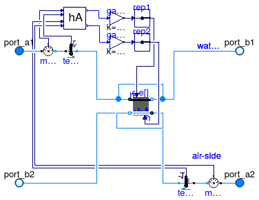
 Buildings.Fluid.HeatExchangers.DryCoilCounterFlow
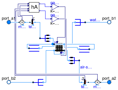
Counterflow coil with discretization along the flow paths and without humidity condensation

Information
Model of a discretized coil without water vapor condensation.
The coil consists of two flow paths which are, at the design flow direction,
in opposite direction to model a counterflow heat exchanger.
The flow paths are discretized into nEle elements.
Each element is modeled by an instance of
Buildings.Fluid.HeatExchangers.BaseClasses.HexElement.
Each element has a state variable for the metal.
The convective heat transfer coefficients can, for each fluid individually, be computed as a function of the flow rate and/or the temperature, or assigned to a constant. This computation is done using an instance of Buildings.Fluid.HeatExchangers.BaseClasses.HADryCoil.
To model humidity condensation, use the model Buildings.Fluid.HeatExchangers.WetCoilCounterFlow instead of this model, as this model computes only sensible heat transfer.
Extends from Buildings.Fluid.Interfaces.PartialFourPortInterface (Partial model transporting fluid between two ports without storing mass or energy), Buildings.Fluid.Interfaces.FourPortFlowResistanceParameters (Parameters for flow resistance for models with four ports).
Parameters
| Type | Name | Default | Description |
|---|---|---|---|
| replaceable package Medium1 | PartialMedium | Medium 1 in the component | |
| replaceable package Medium2 | PartialMedium | Medium 2 in the component | |
| Nominal condition | |||
| MassFlowRate | m1_flow_nominal | Nominal mass flow rate [kg/s] | |
| MassFlowRate | m2_flow_nominal | Nominal mass flow rate [kg/s] | |
| PressureDifference | dp1_nominal | Pressure difference [Pa] | |
| PressureDifference | dp2_nominal | Pressure difference [Pa] | |
| ThermalConductance | UA_nominal | Thermal conductance at nominal flow, used to compute heat capacity [W/K] | |
| Real | r_nominal | 2/3 | Ratio between air-side and water-side convective heat transfer coefficient |
| Time | tau1 | 20 | Time constant at nominal flow for medium 1 [s] |
| Time | tau2 | 1 | Time constant at nominal flow for medium 2 [s] |
| Time | tau_m | 20 | Time constant of metal at nominal UA value [s] |
| Geometry | |||
| Integer | nEle | 4 | Number of pipe segments used for discretization |
| Assumptions | |||
| Boolean | allowFlowReversal1 | true | = false to simplify equations, assuming, but not enforcing, no flow reversal for medium 1 |
| Boolean | allowFlowReversal2 | true | = false to simplify equations, assuming, but not enforcing, no flow reversal for medium 2 |
| Advanced | |||
| MassFlowRate | m1_flow_small | 1E-4*abs(m1_flow_nominal) | Small mass flow rate for regularization of zero flow [kg/s] |
| MassFlowRate | m2_flow_small | 1E-4*abs(m2_flow_nominal) | Small mass flow rate for regularization of zero flow [kg/s] |
| Diagnostics | |||
| Boolean | show_T | false | = true, if actual temperature at port is computed |
| Flow resistance | |||
| Medium 1 | |||
| Boolean | computeFlowResistance1 | false | =true, compute flow resistance. Set to false to assume no friction |
| Boolean | from_dp1 | false | = true, use m_flow = f(dp) else dp = f(m_flow) |
| Boolean | linearizeFlowResistance1 | false | = true, use linear relation between m_flow and dp for any flow rate |
| Real | deltaM1 | 0.1 | Fraction of nominal flow rate where flow transitions to laminar |
| Medium 2 | |||
| Boolean | computeFlowResistance2 | false | =true, compute flow resistance. Set to false to assume no friction |
| Boolean | from_dp2 | false | = true, use m_flow = f(dp) else dp = f(m_flow) |
| Boolean | linearizeFlowResistance2 | false | = true, use linear relation between m_flow and dp for any flow rate |
| Real | deltaM2 | 0.1 | Fraction of nominal flow rate where flow transitions to laminar |
| Dynamics | |||
| Equations | |||
| Dynamics | energyDynamics | Modelica.Fluid.Types.Dynamic... | Formulation of energy balance |
| Heat transfer | |||
| Boolean | waterSideFlowDependent | true | Set to false to make water-side hA independent of mass flow rate |
| Boolean | airSideFlowDependent | true | Set to false to make air-side hA independent of mass flow rate |
| Boolean | waterSideTemperatureDependent | false | Set to false to make water-side hA independent of temperature |
| Boolean | airSideTemperatureDependent | false | Set to false to make air-side hA independent of temperature |
Connectors
| Type | Name | Description |
|---|---|---|
| FluidPort_a | port_a1 | Fluid connector a1 (positive design flow direction is from port_a1 to port_b1) |
| FluidPort_b | port_b1 | Fluid connector b1 (positive design flow direction is from port_a1 to port_b1) |
| FluidPort_a | port_a2 | Fluid connector a2 (positive design flow direction is from port_a2 to port_b2) |
| FluidPort_b | port_b2 | Fluid connector b2 (positive design flow direction is from port_a2 to port_b2) |
Modelica definition
 Buildings.Fluid.HeatExchangers.DryCoilDiscretized
Coil with discretization along the flow paths and no humidity condensation
Information
Model of a discretized coil with no water vapor condensation.
The coil consists of nReg registers
that are perpendicular to the air flow path. Each register consists of nPipPar
parallel pipes, and each pipe can be divided into nPipSeg pipe segments along
the pipe length. Thus, the smallest element of the coil consists of a pipe
segment. Each pipe segment is modeled by an instance of
Buildings.Fluid.HeatExchangers.BaseClasses.HexElement.
Each element has a state variable for the metal.
If the parameter energyDynamics is different from
Modelica.Fluid.Types.Dynamics.SteadyState, then
a mixing volume of length dl is added to the duct connection. This can
help reducing the dimension of the nonlinear system of equations.
The convective heat transfer coefficients can, for each fluid individually, be computed as a function of the flow rate and/or the temperature, or assigned to a constant. This computation is done using an instance of Buildings.Fluid.HeatExchangers.BaseClasses.HADryCoil.
In this model, the water (or liquid) flow path
needs to be connected to port_a1 and port_b1, and
the air flow path need to be connected to the other two ports.
To model humidity condensation, use the model Buildings.Fluid.HeatExchangers.WetCoilDiscretized instead of this model, as this model computes only sensible heat transfer.
Extends from Buildings.Fluid.Interfaces.PartialFourPortInterface (Partial model transporting fluid between two ports without storing mass or energy), Buildings.Fluid.Interfaces.FourPortFlowResistanceParameters (Parameters for flow resistance for models with four ports).
Parameters
| Type | Name | Default | Description |
|---|---|---|---|
| replaceable package Medium1 | PartialMedium | Medium 1 in the component | |
| replaceable package Medium2 | PartialMedium | Medium 2 in the component | |
| Nominal condition | |||
| MassFlowRate | m1_flow_nominal | Nominal mass flow rate [kg/s] | |
| MassFlowRate | m2_flow_nominal | Nominal mass flow rate [kg/s] | |
| PressureDifference | dp1_nominal | Pressure difference [Pa] | |
| PressureDifference | dp2_nominal | Pressure difference [Pa] | |
| ThermalConductance | UA_nominal | Thermal conductance at nominal flow, used to compute heat capacity [W/K] | |
| Time | tau1 | 20 | Time constant at nominal flow for medium 1 [s] |
| Time | tau2 | 1 | Time constant at nominal flow for medium 2 [s] |
| Time | tau_m | 20 | Time constant of metal at nominal UA value [s] |
| Geometry | |||
| Integer | nReg | 2 | Number of registers |
| Integer | nPipPar | 3 | Number of parallel pipes in each register |
| Integer | nPipSeg | 4 | Number of pipe segments per register used for discretization |
| Length | dh1 | 0.025 | Hydraulic diameter for a single pipe [m] |
| Length | dh2 | 1 | Hydraulic diameter for duct [m] |
| Initialization | |||
| MassFlowRate | mStart_flow_a1 | m1_flow_nominal | Guess value for mass flow rate at port_a1 [kg/s] |
| MassFlowRate | mStart_flow_a2 | m2_flow_nominal | Guess value for mass flow rate at port_a2 [kg/s] |
| Assumptions | |||
| Boolean | allowFlowReversal1 | true | = false to simplify equations, assuming, but not enforcing, no flow reversal for medium 1 |
| Boolean | allowFlowReversal2 | true | = false to simplify equations, assuming, but not enforcing, no flow reversal for medium 2 |
| Advanced | |||
| MassFlowRate | m1_flow_small | 1E-4*abs(m1_flow_nominal) | Small mass flow rate for regularization of zero flow [kg/s] |
| MassFlowRate | m2_flow_small | 1E-4*abs(m2_flow_nominal) | Small mass flow rate for regularization of zero flow [kg/s] |
| Boolean | use_dh1 | false | Set to true to specify hydraulic diameter for pipe pressure drop |
| Boolean | use_dh2 | false | Set to true to specify hydraulic diameter for duct pressure drop) |
| Real | ReC_1 | 4000 | Reynolds number where transition to turbulent starts inside pipes |
| Real | ReC_2 | 4000 | Reynolds number where transition to turbulent starts inside ducts |
| Diagnostics | |||
| Boolean | show_T | false | = true, if actual temperature at port is computed |
| Flow resistance | |||
| Medium 1 | |||
| Boolean | computeFlowResistance1 | true | =true, compute flow resistance. Set to false to assume no friction |
| Boolean | from_dp1 | false | = true, use m_flow = f(dp) else dp = f(m_flow) |
| Boolean | linearizeFlowResistance1 | false | = true, use linear relation between m_flow and dp for any flow rate |
| Real | deltaM1 | 0.1 | Fraction of nominal flow rate where flow transitions to laminar |
| Medium 2 | |||
| Boolean | computeFlowResistance2 | true | =true, compute flow resistance. Set to false to assume no friction |
| Boolean | from_dp2 | false | = true, use m_flow = f(dp) else dp = f(m_flow) |
| Boolean | linearizeFlowResistance2 | false | = true, use linear relation between m_flow and dp for any flow rate |
| Real | deltaM2 | 0.1 | Fraction of nominal flow rate where flow transitions to laminar |
| Dynamics | |||
| Equations | |||
| Dynamics | energyDynamics | Modelica.Fluid.Types.Dynamic... | Formulation of energy balance |
| Heat transfer | |||
| Boolean | waterSideFlowDependent | false | Set to false to make water-side hA independent of mass flow rate |
| Boolean | airSideFlowDependent | false | Set to false to make air-side hA independent of mass flow rate |
| Boolean | waterSideTemperatureDependent | false | Set to false to make water-side hA independent of temperature |
Connectors
| Type | Name | Description |
|---|---|---|
| FluidPort_a | port_a1 | Fluid connector a1 (positive design flow direction is from port_a1 to port_b1) |
| FluidPort_b | port_b1 | Fluid connector b1 (positive design flow direction is from port_a1 to port_b1) |
| FluidPort_a | port_a2 | Fluid connector a2 (positive design flow direction is from port_a2 to port_b2) |
| FluidPort_b | port_b2 | Fluid connector b2 (positive design flow direction is from port_a2 to port_b2) |
Modelica definition
 Buildings.Fluid.HeatExchangers.DryEffectivenessNTU
Heat exchanger with effectiveness - NTU relation and no moisture condensation

Information
Model of a heat exchanger without humidity condensation. This model transfers heat in the amount of
Q = Qmax ε
ε = f(NTU, Z, flowRegime),
where Qmax is the maximum heat that can be transferred, ε is the heat transfer effectiveness, NTU is the Number of Transfer Units, Z is the ratio of minimum to maximum capacity flow rate and flowRegime is the heat exchanger flow regime. such as parallel flow, cross flow or counter flow.
The flow regimes depend on the heat exchanger configuration. All configurations defined in Buildings.Fluid.Types.HeatExchangerConfiguration are supported.
For a heat and moisture exchanger, use Buildings.Fluid.MassExchangers.ConstantEffectiveness instead of this model.
Extends from Buildings.Fluid.HeatExchangers.BaseClasses.PartialEffectiveness (Partial model to implement heat exchangers based on effectiveness model).
Parameters
| Type | Name | Default | Description |
|---|---|---|---|
| replaceable package Medium1 | PartialMedium | Medium 1 in the component | |
| replaceable package Medium2 | PartialMedium | Medium 2 in the component | |
| HeatFlowRate | Q1_flow | eps*QMax_flow | Heat transferred into the medium 1 [W] |
| MassFlowRate | mWat1_flow | 0 | Moisture mass flow rate added to the medium 1 [kg/s] |
| HeatFlowRate | Q2_flow | -Q1_flow | Heat transferred into the medium 2 [W] |
| MassFlowRate | mWat2_flow | 0 | Moisture mass flow rate added to the medium 2 [kg/s] |
| Boolean | sensibleOnly1 | true | Set to true if sensible exchange only for medium 1 |
| Boolean | sensibleOnly2 | true | Set to true if sensible exchange only for medium 2 |
| HeatExchangerConfiguration | configuration | Heat exchanger configuration | |
| Real | r_nominal | 2/3 | Ratio between air-side and water-side convective heat transfer (hA-value) at nominal condition |
| Nominal condition | |||
| MassFlowRate | m1_flow_nominal | Nominal mass flow rate [kg/s] | |
| MassFlowRate | m2_flow_nominal | Nominal mass flow rate [kg/s] | |
| PressureDifference | dp1_nominal | Pressure difference [Pa] | |
| PressureDifference | dp2_nominal | Pressure difference [Pa] | |
| HeatFlowRate | Q_flow_nominal | Nominal heat transfer [W] | |
| Temperature | T_a1_nominal | Nominal temperature at port a1 [K] | |
| Temperature | T_a2_nominal | Nominal temperature at port a2 [K] | |
| Assumptions | |||
| Boolean | allowFlowReversal1 | true | = false to simplify equations, assuming, but not enforcing, no flow reversal for medium 1 |
| Boolean | allowFlowReversal2 | true | = false to simplify equations, assuming, but not enforcing, no flow reversal for medium 2 |
| Advanced | |||
| MassFlowRate | m1_flow_small | 1E-4*abs(m1_flow_nominal) | Small mass flow rate for regularization of zero flow [kg/s] |
| MassFlowRate | m2_flow_small | 1E-4*abs(m2_flow_nominal) | Small mass flow rate for regularization of zero flow [kg/s] |
| Boolean | homotopyInitialization | true | = true, use homotopy method |
| Diagnostics | |||
| Boolean | show_T | false | = true, if actual temperature at port is computed |
| Flow resistance | |||
| Medium 1 | |||
| Boolean | from_dp1 | false | = true, use m_flow = f(dp) else dp = f(m_flow) |
| Boolean | linearizeFlowResistance1 | false | = true, use linear relation between m_flow and dp for any flow rate |
| Real | deltaM1 | 0.1 | Fraction of nominal flow rate where flow transitions to laminar |
| Medium 2 | |||
| Boolean | from_dp2 | false | = true, use m_flow = f(dp) else dp = f(m_flow) |
| Boolean | linearizeFlowResistance2 | false | = true, use linear relation between m_flow and dp for any flow rate |
| Real | deltaM2 | 0.1 | Fraction of nominal flow rate where flow transitions to laminar |
Connectors
| Type | Name | Description |
|---|---|---|
| FluidPort_a | port_a1 | Fluid connector a1 (positive design flow direction is from port_a1 to port_b1) |
| FluidPort_b | port_b1 | Fluid connector b1 (positive design flow direction is from port_a1 to port_b1) |
| FluidPort_a | port_a2 | Fluid connector a2 (positive design flow direction is from port_a2 to port_b2) |
| FluidPort_b | port_b2 | Fluid connector b2 (positive design flow direction is from port_a2 to port_b2) |
Modelica definition
 Buildings.Fluid.HeatExchangers.EvaporatorCondenser
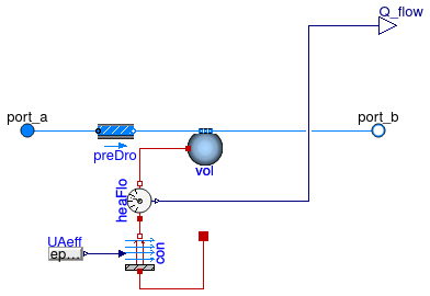
Evaporator or condenser with refrigerant experiencing constant temperature phase change
Information
Model for a constant temperature evaporator or condenser based on a epsilon-NTU heat exchanger model.
The heat exchanger effectiveness is calculated from the number of transfer units (NTU):
ε = 1 - exp(UA ⁄ (ṁ cp))
Optionally, this model can have a flow resistance.
If no flow resistance is requested, set dp_nominal=0.
Limitations
This model does not consider any superheating or supercooling on the refrigerant side. The refrigerant is considered to exchange heat at a constant temperature throughout the heat exchanger.
Extends from Interfaces.TwoPortHeatMassExchanger (Partial model transporting one fluid stream with storing mass or energy).
Parameters
| Type | Name | Default | Description |
|---|---|---|---|
| replaceable package Medium | PartialMedium | Medium in the component | |
| ThermalConductance | UA | Thermal conductance of heat exchanger [W/K] | |
| Nominal condition | |||
| MassFlowRate | m_flow_nominal | Nominal mass flow rate [kg/s] | |
| PressureDifference | dp_nominal | Pressure difference [Pa] | |
| Assumptions | |||
| Boolean | allowFlowReversal | true | = false to simplify equations, assuming, but not enforcing, no flow reversal |
| Advanced | |||
| MassFlowRate | m_flow_small | 1E-4*abs(m_flow_nominal) | Small mass flow rate for regularization of zero flow [kg/s] |
| Boolean | homotopyInitialization | true | = true, use homotopy method |
| Diagnostics | |||
| Boolean | show_T | false | = true, if actual temperature at port is computed |
| Flow resistance | |||
| Boolean | from_dp | false | = true, use m_flow = f(dp) else dp = f(m_flow) |
| Boolean | linearizeFlowResistance | false | = true, use linear relation between m_flow and dp for any flow rate |
| Real | deltaM | 0.1 | Fraction of nominal flow rate where flow transitions to laminar |
| Dynamics | |||
| Nominal condition | |||
| Time | tau | 30 | Time constant at nominal flow (if energyDynamics <> SteadyState) [s] |
| Equations | |||
| Dynamics | energyDynamics | Modelica.Fluid.Types.Dynamic... | Type of energy balance: dynamic (3 initialization options) or steady state |
| Dynamics | massDynamics | energyDynamics | Type of mass balance: dynamic (3 initialization options) or steady state |
| Initialization | |||
| AbsolutePressure | p_start | Medium.p_default | Start value of pressure [Pa] |
| Temperature | T_start | Medium.T_default | Start value of temperature [K] |
| MassFraction | X_start[Medium.nX] | Medium.X_default | Start value of mass fractions m_i/m [kg/kg] |
| ExtraProperty | C_start[Medium.nC] | fill(0, Medium.nC) | Start value of trace substances |
Connectors
| Type | Name | Description |
|---|---|---|
| FluidPort_a | port_a | Fluid connector a (positive design flow direction is from port_a to port_b) |
| FluidPort_b | port_b | Fluid connector b (positive design flow direction is from port_a to port_b) |
| output RealOutput | Q_flow | Heat added to the fluid [W] |
| HeatPort_a | port_ref | Temperature and heat flow from the refrigerant |
Modelica definition
 Buildings.Fluid.HeatExchangers.HeaterCooler_T
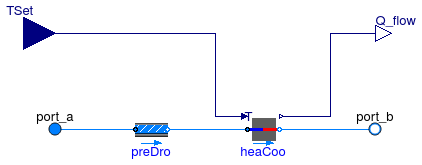
Ideal heater or cooler with a prescribed outlet temperature
Information
Model for an ideal heater or cooler with a prescribed outlet temperature.
This model forces the outlet temperature at port_b to be equal to the temperature
of the input signal TSet, subject to optional limits on the
heating or cooling capacity Q_flow_max and Q_flow_min.
For unlimited capacity, set Q_flow_maxHeat = Modelica.Constant.inf
and Q_flow_maxCool=-Modelica.Constant.inf.
The output signal Q_flow is the heat added (for heating) or subtracted (for cooling)
to the medium if the flow rate is from port_a to port_b.
If the flow is reversed, then Q_flow=0.
The outlet temperature at port_a is not affected by this model.
If the parameter energyDynamics is not equal to
Modelica.Fluid.Types.Dynamics.SteadyState,
the component models the dynamic response using a first order differential equation.
The time constant of the component is equal to the parameter tau.
This time constant is adjusted based on the mass flow rate using
τeff = τ |ṁ| ⁄ ṁnom
where τeff is the effective time constant for the given mass flow rate ṁ and τ is the time constant at the nominal mass flow rate ṁnom. This type of dynamics is equal to the dynamics that a completely mixed control volume would have.
Optionally, this model can have a flow resistance.
If no flow resistance is requested, set dp_nominal=0.
For a model that uses a control signal u ∈ [0, 1] and multiplies this with the nominal heating or cooling power, use Buildings.Fluid.HeatExchangers.HeaterCooler_u
Limitations
This model only adds or removes heat for the flow from
port_a to port_b.
The enthalpy of the reverse flow is not affected by this model.
This model does not affect the humidity of the air. Therefore, if used to cool air below the dew point temperature, the water mass fraction will not change.
Validation
The model has been validated against the analytical solution in the examples Buildings.Fluid.HeatExchangers.Validation.HeaterCooler_T and Buildings.Fluid.HeatExchangers.Validation.HeaterCooler_T_dynamic.
Extends from Buildings.Fluid.Interfaces.PartialTwoPortInterface (Partial model transporting fluid between two ports without storing mass or energy), Buildings.Fluid.Interfaces.TwoPortFlowResistanceParameters (Parameters for flow resistance for models with two ports), Buildings.Fluid.Interfaces.PrescribedOutletStateParameters (Parameters for models with prescribed outlet state).
Parameters
| Type | Name | Default | Description |
|---|---|---|---|
| replaceable package Medium | PartialMedium | Medium in the component | |
| HeatFlowRate | Q_flow_maxHeat | Modelica.Constants.inf | Maximum heat flow rate for heating (positive) [W] |
| HeatFlowRate | Q_flow_maxCool | -Modelica.Constants.inf | Maximum heat flow rate for cooling (negative) [W] |
| Nominal condition | |||
| MassFlowRate | m_flow_nominal | Nominal mass flow rate [kg/s] | |
| PressureDifference | dp_nominal | Pressure difference [Pa] | |
| Assumptions | |||
| Boolean | allowFlowReversal | true | = false to simplify equations, assuming, but not enforcing, no flow reversal |
| Advanced | |||
| MassFlowRate | m_flow_small | 1E-4*abs(m_flow_nominal) | Small mass flow rate for regularization of zero flow [kg/s] |
| Boolean | homotopyInitialization | true | = true, use homotopy method |
| Diagnostics | |||
| Boolean | show_T | false | = true, if actual temperature at port is computed |
| Flow resistance | |||
| Boolean | computeFlowResistance | (abs(dp_nominal) > Modelica.... | =true, compute flow resistance. Set to false to assume no friction |
| Boolean | from_dp | false | = true, use m_flow = f(dp) else dp = f(m_flow) |
| Boolean | linearizeFlowResistance | false | = true, use linear relation between m_flow and dp for any flow rate |
| Real | deltaM | 0.1 | Fraction of nominal flow rate where flow transitions to laminar |
| Dynamics | |||
| Time | tau | 10 | Time constant at nominal flow rate (used if energyDynamics <> Modelica.Fluid.Types.Dynamics.SteadyState) [s] |
| Initialization | |||
| Temperature | T_start | Medium.T_default | Initial or guess value of set point [K] |
| Equations | |||
| Dynamics | energyDynamics | Modelica.Fluid.Types.Dynamic... | Type of energy balance: dynamic (3 initialization options) or steady state |
Connectors
| Type | Name | Description |
|---|---|---|
| FluidPort_a | port_a | Fluid connector a (positive design flow direction is from port_a to port_b) |
| FluidPort_b | port_b | Fluid connector b (positive design flow direction is from port_a to port_b) |
| input RealInput | TSet | Set point temperature of the fluid that leaves port_b [K] |
| output RealOutput | Q_flow | Heat added to the fluid (if flow is from port_a to port_b) [W] |
Modelica definition
 Buildings.Fluid.HeatExchangers.HeaterCooler_u
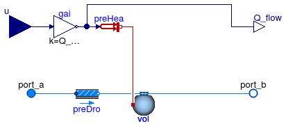
Heater or cooler with prescribed heat flow rate
Information
Model for an ideal heater or cooler with prescribed heat flow rate to the medium.
This model adds heat in the amount of Q_flow = u Q_flow_nominal to the medium.
The input signal u and the nominal heat flow rate Q_flow_nominal
can be positive or negative.
Optionally, this model can have a flow resistance.
If no flow resistance is requested, set dp_nominal=0.
For a model that uses as an input the fluid temperature leaving at
port_b, use
Buildings.Fluid.HeatExchangers.HeaterCooler_T
Limitations
This model does not affect the humidity of the air. Therefore, if used to cool air below the dew point temperature, the water mass fraction will not change.
Validation
The model has been validated against the analytical solution in the example Buildings.Fluid.HeatExchangers.Validation.HeaterCooler_u.
Extends from Buildings.Fluid.Interfaces.TwoPortHeatMassExchanger (Partial model transporting one fluid stream with storing mass or energy).
Parameters
| Type | Name | Default | Description |
|---|---|---|---|
| replaceable package Medium | PartialMedium | Medium in the component | |
| HeatFlowRate | Q_flow_nominal | Heat flow rate at u=1, positive for heating [W] | |
| Nominal condition | |||
| MassFlowRate | m_flow_nominal | Nominal mass flow rate [kg/s] | |
| PressureDifference | dp_nominal | Pressure difference [Pa] | |
| Assumptions | |||
| Boolean | allowFlowReversal | true | = false to simplify equations, assuming, but not enforcing, no flow reversal |
| Advanced | |||
| MassFlowRate | m_flow_small | 1E-4*abs(m_flow_nominal) | Small mass flow rate for regularization of zero flow [kg/s] |
| Boolean | homotopyInitialization | true | = true, use homotopy method |
| Diagnostics | |||
| Boolean | show_T | false | = true, if actual temperature at port is computed |
| Flow resistance | |||
| Boolean | from_dp | false | = true, use m_flow = f(dp) else dp = f(m_flow) |
| Boolean | linearizeFlowResistance | false | = true, use linear relation between m_flow and dp for any flow rate |
| Real | deltaM | 0.1 | Fraction of nominal flow rate where flow transitions to laminar |
| Dynamics | |||
| Nominal condition | |||
| Time | tau | 30 | Time constant at nominal flow (if energyDynamics <> SteadyState) [s] |
| Equations | |||
| Dynamics | energyDynamics | Modelica.Fluid.Types.Dynamic... | Type of energy balance: dynamic (3 initialization options) or steady state |
| Dynamics | massDynamics | energyDynamics | Type of mass balance: dynamic (3 initialization options) or steady state |
| Initialization | |||
| AbsolutePressure | p_start | Medium.p_default | Start value of pressure [Pa] |
| Temperature | T_start | Medium.T_default | Start value of temperature [K] |
| MassFraction | X_start[Medium.nX] | Medium.X_default | Start value of mass fractions m_i/m [kg/kg] |
| ExtraProperty | C_start[Medium.nC] | fill(0, Medium.nC) | Start value of trace substances |
Connectors
| Type | Name | Description |
|---|---|---|
| FluidPort_a | port_a | Fluid connector a (positive design flow direction is from port_a to port_b) |
| FluidPort_b | port_b | Fluid connector b (positive design flow direction is from port_a to port_b) |
| input RealInput | u | Control input |
| output RealOutput | Q_flow | Heat added to the fluid [W] |
Modelica definition
 Buildings.Fluid.HeatExchangers.WetCoilCounterFlow
Counterflow coil with discretization along the flow paths and humidity condensation
Information
Model of a discretized coil with water vapor condensation.
The coil consists of two flow paths which are, at the design flow direction,
in opposite direction to model a counterflow heat exchanger.
The flow paths are discretized into nEle elements.
Each element is modeled by an instance of
Buildings.Fluid.HeatExchangers.BaseClasses.HexElement.
Each element has a state variable for the metal.
The convective heat transfer coefficients can, for each fluid individually, be computed as a function of the flow rate and/or the temperature, or assigned to a constant. This computation is done using an instance of Buildings.Fluid.HeatExchangers.BaseClasses.HADryCoil.
In this model, the water (or liquid) flow path
needs to be connected to port_a1 and port_b1, and
the air flow path needs to be connected to the other two ports.
The mass transfer from the fluid 2 to the metal is computed using a similarity law between heat and mass transfer, as implemented by the model Buildings.Fluid.HeatExchangers.BaseClasses.MassExchange.
This model can only be used with medium models that
implement the function enthalpyOfLiquid and that contain
an integer variable Water whose value is the element number where
the water vapor is stored in the species concentration vector. Examples for
such media are
Buildings.Media.Air and
Modelica.Media.Air.MoistAir.
To model this coil for conditions without humidity condensation, use the model Buildings.Fluid.HeatExchangers.DryCoilCounterFlow instead of this model.
Extends from Buildings.Fluid.HeatExchangers.DryCoilCounterFlow (Counterflow coil with discretization along the flow paths and without humidity condensation).
Parameters
| Type | Name | Default | Description |
|---|---|---|---|
| replaceable package Medium1 | PartialMedium | Medium 1 in the component | |
| replaceable package Medium2 | PartialMedium | Medium 2 in the component | |
| Nominal condition | |||
| MassFlowRate | m1_flow_nominal | Nominal mass flow rate [kg/s] | |
| MassFlowRate | m2_flow_nominal | Nominal mass flow rate [kg/s] | |
| PressureDifference | dp1_nominal | Pressure difference [Pa] | |
| PressureDifference | dp2_nominal | Pressure difference [Pa] | |
| ThermalConductance | UA_nominal | Thermal conductance at nominal flow, used to compute heat capacity [W/K] | |
| Real | r_nominal | 2/3 | Ratio between air-side and water-side convective heat transfer coefficient |
| Time | tau1 | 20 | Time constant at nominal flow for medium 1 [s] |
| Time | tau2 | 1 | Time constant at nominal flow for medium 2 [s] |
| Time | tau_m | 20 | Time constant of metal at nominal UA value [s] |
| Geometry | |||
| Integer | nEle | 4 | Number of pipe segments used for discretization |
| Assumptions | |||
| Boolean | allowFlowReversal1 | true | = false to simplify equations, assuming, but not enforcing, no flow reversal for medium 1 |
| Boolean | allowFlowReversal2 | true | = false to simplify equations, assuming, but not enforcing, no flow reversal for medium 2 |
| Advanced | |||
| MassFlowRate | m1_flow_small | 1E-4*abs(m1_flow_nominal) | Small mass flow rate for regularization of zero flow [kg/s] |
| MassFlowRate | m2_flow_small | 1E-4*abs(m2_flow_nominal) | Small mass flow rate for regularization of zero flow [kg/s] |
| Diagnostics | |||
| Boolean | show_T | false | = true, if actual temperature at port is computed |
| Flow resistance | |||
| Medium 1 | |||
| Boolean | from_dp1 | false | = true, use m_flow = f(dp) else dp = f(m_flow) |
| Boolean | linearizeFlowResistance1 | false | = true, use linear relation between m_flow and dp for any flow rate |
| Real | deltaM1 | 0.1 | Fraction of nominal flow rate where flow transitions to laminar |
| Medium 2 | |||
| Boolean | from_dp2 | false | = true, use m_flow = f(dp) else dp = f(m_flow) |
| Boolean | linearizeFlowResistance2 | false | = true, use linear relation between m_flow and dp for any flow rate |
| Real | deltaM2 | 0.1 | Fraction of nominal flow rate where flow transitions to laminar |
| Dynamics | |||
| Equations | |||
| Dynamics | energyDynamics | Modelica.Fluid.Types.Dynamic... | Formulation of energy balance |
| Heat transfer | |||
| Boolean | waterSideFlowDependent | true | Set to false to make water-side hA independent of mass flow rate |
| Boolean | airSideFlowDependent | true | Set to false to make air-side hA independent of mass flow rate |
| Boolean | waterSideTemperatureDependent | false | Set to false to make water-side hA independent of temperature |
| Boolean | airSideTemperatureDependent | false | Set to false to make air-side hA independent of temperature |
Connectors
| Type | Name | Description |
|---|---|---|
| replaceable package Medium2 | Medium 2 in the component | |
| FluidPort_a | port_a1 | Fluid connector a1 (positive design flow direction is from port_a1 to port_b1) |
| FluidPort_b | port_b1 | Fluid connector b1 (positive design flow direction is from port_a1 to port_b1) |
| FluidPort_a | port_a2 | Fluid connector a2 (positive design flow direction is from port_a2 to port_b2) |
| FluidPort_b | port_b2 | Fluid connector b2 (positive design flow direction is from port_a2 to port_b2) |
Modelica definition
 Buildings.Fluid.HeatExchangers.WetCoilDiscretized
Coil with discretization along the flow paths and humidity condensation

Information
Model of a discretized coil with humidity condensation. This model is identical to Buildings.Fluid.HeatExchangers.DryCoilDiscretized but in addition, the mass transfer from fluid 2 to the metal is computed. The mass transfer is computed using a similarity law between heat and mass transfer, as implemented by the model Buildings.Fluid.HeatExchangers.BaseClasses.MassExchange. See this model for details.
This model can only be used with medium models that
implement the function enthalpyOfLiquid and that contain
an integer variable Water whose value is the element number where
the water vapor is stored in the species concentration vector. Examples for
such media are
Buildings.Media.Air and
Modelica.Media.Air.MoistAir.
Extends from DryCoilDiscretized (Coil with discretization along the flow paths and no humidity condensation).
Parameters
| Type | Name | Default | Description |
|---|---|---|---|
| replaceable package Medium1 | PartialMedium | Medium 1 in the component | |
| replaceable package Medium2 | PartialMedium | Medium 2 in the component | |
| Nominal condition | |||
| MassFlowRate | m1_flow_nominal | Nominal mass flow rate [kg/s] | |
| MassFlowRate | m2_flow_nominal | Nominal mass flow rate [kg/s] | |
| PressureDifference | dp1_nominal | Pressure difference [Pa] | |
| PressureDifference | dp2_nominal | Pressure difference [Pa] | |
| ThermalConductance | UA_nominal | Thermal conductance at nominal flow, used to compute heat capacity [W/K] | |
| Time | tau1 | 20 | Time constant at nominal flow for medium 1 [s] |
| Time | tau2 | 1 | Time constant at nominal flow for medium 2 [s] |
| Time | tau_m | 20 | Time constant of metal at nominal UA value [s] |
| Geometry | |||
| Integer | nReg | 2 | Number of registers |
| Integer | nPipPar | 3 | Number of parallel pipes in each register |
| Integer | nPipSeg | 4 | Number of pipe segments per register used for discretization |
| Length | dh1 | 0.025 | Hydraulic diameter for a single pipe [m] |
| Length | dh2 | 1 | Hydraulic diameter for duct [m] |
| Initialization | |||
| MassFlowRate | mStart_flow_a1 | m1_flow_nominal | Guess value for mass flow rate at port_a1 [kg/s] |
| MassFlowRate | mStart_flow_a2 | m2_flow_nominal | Guess value for mass flow rate at port_a2 [kg/s] |
| Assumptions | |||
| Boolean | allowFlowReversal1 | true | = false to simplify equations, assuming, but not enforcing, no flow reversal for medium 1 |
| Boolean | allowFlowReversal2 | true | = false to simplify equations, assuming, but not enforcing, no flow reversal for medium 2 |
| Advanced | |||
| MassFlowRate | m1_flow_small | 1E-4*abs(m1_flow_nominal) | Small mass flow rate for regularization of zero flow [kg/s] |
| MassFlowRate | m2_flow_small | 1E-4*abs(m2_flow_nominal) | Small mass flow rate for regularization of zero flow [kg/s] |
| Boolean | use_dh1 | false | Set to true to specify hydraulic diameter for pipe pressure drop |
| Boolean | use_dh2 | false | Set to true to specify hydraulic diameter for duct pressure drop) |
| Real | ReC_1 | 4000 | Reynolds number where transition to turbulent starts inside pipes |
| Real | ReC_2 | 4000 | Reynolds number where transition to turbulent starts inside ducts |
| Diagnostics | |||
| Boolean | show_T | false | = true, if actual temperature at port is computed |
| Flow resistance | |||
| Medium 1 | |||
| Boolean | from_dp1 | false | = true, use m_flow = f(dp) else dp = f(m_flow) |
| Boolean | linearizeFlowResistance1 | false | = true, use linear relation between m_flow and dp for any flow rate |
| Real | deltaM1 | 0.1 | Fraction of nominal flow rate where flow transitions to laminar |
| Medium 2 | |||
| Boolean | from_dp2 | false | = true, use m_flow = f(dp) else dp = f(m_flow) |
| Boolean | linearizeFlowResistance2 | false | = true, use linear relation between m_flow and dp for any flow rate |
| Real | deltaM2 | 0.1 | Fraction of nominal flow rate where flow transitions to laminar |
| Dynamics | |||
| Equations | |||
| Dynamics | energyDynamics | Modelica.Fluid.Types.Dynamic... | Formulation of energy balance |
| Heat transfer | |||
| Boolean | waterSideFlowDependent | false | Set to false to make water-side hA independent of mass flow rate |
| Boolean | airSideFlowDependent | false | Set to false to make air-side hA independent of mass flow rate |
| Boolean | waterSideTemperatureDependent | false | Set to false to make water-side hA independent of temperature |
Connectors
| Type | Name | Description |
|---|---|---|
| replaceable package Medium2 | Medium 2 in the component | |
| FluidPort_a | port_a1 | Fluid connector a1 (positive design flow direction is from port_a1 to port_b1) |
| FluidPort_b | port_b1 | Fluid connector b1 (positive design flow direction is from port_a1 to port_b1) |
| FluidPort_a | port_a2 | Fluid connector a2 (positive design flow direction is from port_a2 to port_b2) |
| FluidPort_b | port_b2 | Fluid connector b2 (positive design flow direction is from port_a2 to port_b2) |