Package with example models
Information
This package contains examples for the use of models that can be found in
Buildings.Electrical.AC.ThreePhasesBalanced.Loads.
Extends from Modelica.Icons.ExamplesPackage (Icon for packages containing runnable examples).
Package Content
| Name |
Description |
 Impedances Impedances
|
Example that illustrates the use of the impedance models |
 ParallelLoads ParallelLoads
|
Example that illustrates the use of the load models |
 ThreePhases ThreePhases
|
Example that provides a comparison between AC one phase and three-phase balanced |
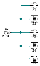
Example that illustrates the use of the impedance models

Information
This model illustrates the use of the impedance models.
The impedances have unitary values such that the RMS value of the voltage and of the current are the same.
Extends from Modelica.Icons.Example (Icon for runnable examples).
Modelica definition
model Impedances
extends Modelica.Icons.Example;
Sources.FixedVoltage sou(f=60, V=480) ;
Impedance Z1(R=0,
inductive=true,
L=1/(2*Modelica.Constants.pi*60),
star=true) ;
Impedance Z2(R=1, star=true) ;
Impedance Z3(R=0,
inductive=false,
C=1/(2*Modelica.Constants.pi*60),
star=true) ;
Impedance Z4(
inductive=false,
R=1,
C=1/(2*Modelica.Constants.pi*60),
star=true) ;
Impedance Z5(
R=1,
inductive=true,
L=1/(2*Modelica.Constants.pi*60),
star=true) ;
equation
connect(sou.terminal, Z1.terminal);
connect(sou.terminal, Z2.terminal);
connect(sou.terminal, Z3.terminal);
connect(sou.terminal, Z4.terminal);
connect(sou.terminal, Z5.terminal);
end Impedances;
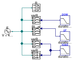
Example that illustrates the use of the load models

Information
This model illustrates the use of the three-phase unbalanced load models.
Extends from Modelica.Icons.Example (Icon for runnable examples).
Modelica definition
model ParallelLoads
extends Modelica.Icons.Example;
Sources.FixedVoltage E(f=60, V=480) ;
Resistive R(P_nominal=-2000, V_nominal=480) ;
Inductive RL_pf(
pf=0.8,
P_nominal=-2000,
use_pf_in=true,
V_nominal=480) ;
Modelica.Blocks.Sources.Ramp load( startTime=0.2, duration=0.3) ;
Inductive varRL_y( P_nominal=-2000,
V_nominal=480,
mode=Buildings.Electrical.Types.Load.VariableZ_y_input) ;
Capacitive varRC_y( P_nominal=-2000,
V_nominal=480,
mode=Buildings.Electrical.Types.Load.VariableZ_y_input) ;
Inductive varRL_P(pf=0.8,
V_nominal=480,
mode=Buildings.Electrical.Types.Load.VariableZ_P_input) ;
Modelica.Blocks.Sources.Ramp pow(
startTime=0.2,
duration=0.3,
height=4000,
offset=-2000) ;
Modelica.Blocks.Sources.Ramp pf(
height=0.2,
duration=0.2,
offset=0.8,
startTime=0.7) ;
equation
connect(E.terminal, R.terminal);
connect(E.terminal, RL_pf.terminal);
connect(E.terminal, varRL_y.terminal);
connect(E.terminal, varRC_y.terminal);
connect(load.y, varRL_y.y);
connect(load.y, varRC_y.y);
connect(E.terminal, varRL_P.terminal);
connect(pow.y, varRL_P.Pow);
connect(pf.y, RL_pf.pf_in);
end ParallelLoads;
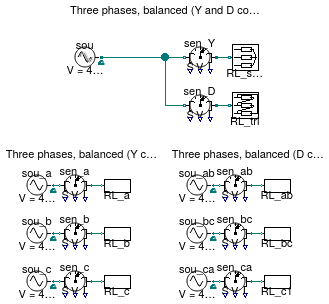
Example that provides a comparison between AC one phase and three-phase balanced

Information
This model illustrates the use of the impedance models and how the three-phase balanced model
can reproduce the same results obtained using three separate one phase circuits.
Extends from Modelica.Icons.Example (Icon for runnable examples).
Modelica definition
model ThreePhases
extends Modelica.Icons.Example;
Modelica.SIunits.Power errorY=
sqrt((sen_Y.S[1] - (sen_a.S[1] + sen_b.S[1] + sen_c.S[1]))^2 +
(sen_Y.S[2] - (sen_a.S[2] + sen_b.S[2] + sen_c.S[2]))^2) ;
Modelica.SIunits.Power errorD=
sqrt((sen_D.S[1] - (sen_ab.S[1] + sen_bc.S[1] + sen_ca.S[1]))^2 +
(sen_D.S[2] - (sen_ab.S[2] + sen_bc.S[2] + sen_ca.S[2]))^2) ;
Sources.FixedVoltage sou(definiteReference=true,
f=60,
V=480) ;
Impedance RL_star(
R=1,
inductive=true,
L=1/(2*Modelica.Constants.pi*60)) ;
OnePhase.Sources.FixedVoltage sou_a(V=480/
sqrt(3), definiteReference=true,
f=60) ;
OnePhase.Sources.FixedVoltage sou_b(
V=480/
sqrt(3),
definiteReference=true,
phiSou=2.0943951023932,
f=60) ;
OnePhase.Sources.FixedVoltage sou_c(
V=480/
sqrt(3),
definiteReference=true,
phiSou=-2.0943951023932,
f=60) ;
OnePhase.Loads.Impedance RL_a(
R=1,
inductive=true,
L=1/(2*Modelica.Constants.pi*60)) ;
OnePhase.Loads.Impedance RL_b(
R=1,
inductive=true,
L=1/(2*Modelica.Constants.pi*60)) ;
OnePhase.Loads.Impedance RL_c(
R=1,
inductive=true,
L=1/(2*Modelica.Constants.pi*60)) ;
Impedance RL_tri(
R=1,
inductive=true,
L=1/(2*Modelica.Constants.pi*60),
star=false) ;
OnePhase.Sources.FixedVoltage sou_ab(
V=480,
phiSou=-0.5235987755983,
definiteReference=true,
f=60) ;
OnePhase.Sources.FixedVoltage sou_bc(
phiSou=1.5707963267949,
V=480,
definiteReference=true,
f=60) ;
OnePhase.Sources.FixedVoltage sou_ca(
phiSou=-3.6651914291881,
V=480,
definiteReference=true,
f=60) ;
OnePhase.Loads.Impedance RL_ab(
R=1,
inductive=true,
L=1/(2*Modelica.Constants.pi*60)) ;
OnePhase.Loads.Impedance RL_bc(
R=1,
inductive=true,
L=1/(2*Modelica.Constants.pi*60)) ;
OnePhase.Loads.Impedance RL_c1(
R=1,
inductive=true,
L=1/(2*Modelica.Constants.pi*60)) ;
OnePhase.Sensors.GeneralizedSensor sen_a ;
OnePhase.Sensors.GeneralizedSensor sen_ab ;
Sensors.GeneralizedSensor sen_Y ;
Sensors.GeneralizedSensor sen_D ;
OnePhase.Sensors.GeneralizedSensor sen_b ;
OnePhase.Sensors.GeneralizedSensor sen_c ;
OnePhase.Sensors.GeneralizedSensor sen_bc ;
OnePhase.Sensors.GeneralizedSensor sen_ca ;
equation
connect(sou_a.terminal, sen_a.terminal_n);
connect(sen_a.terminal_p, RL_a.terminal);
connect(sou_ab.terminal, sen_ab.terminal_n);
connect(sen_ab.terminal_p, RL_ab.terminal);
connect(sou.terminal, sen_Y.terminal_n);
connect(sen_Y.terminal_p, RL_star.terminal);
connect(sou.terminal, sen_D.terminal_n);
connect(sen_D.terminal_p, RL_tri.terminal);
connect(sou_b.terminal, sen_b.terminal_n);
connect(sen_b.terminal_p, RL_b.terminal);
connect(sou_c.terminal, sen_c.terminal_n);
connect(sen_c.terminal_p, RL_c.terminal);
connect(sou_bc.terminal, sen_bc.terminal_n);
connect(sen_bc.terminal_p, RL_bc.terminal);
connect(sou_ca.terminal, sen_ca.terminal_n);
connect(sen_ca.terminal_p, RL_c1.terminal);
end ThreePhases;
http://simulationresearch.lbl.gov/modelica


 Buildings.Electrical.AC.ThreePhasesBalanced.Loads.Examples.Impedances
 Buildings.Electrical.AC.ThreePhasesBalanced.Loads.Examples.ParallelLoads
 Buildings.Electrical.AC.ThreePhasesBalanced.Loads.Examples.ThreePhases