Package of control blocks for fifth generation DHC ETS
Information
This package contains control blocks for energy transfer stations in
fifth generation district heating and cooling systems.
Extends from Modelica.Icons.VariantsPackage (Icon for package containing variants).
Package Content
| Name |
Description |
 Borefield Borefield
|
Borefield controller |
 Chiller Chiller
|
Chiller controller |
 HeatExchanger HeatExchanger
|
District heat exchanger controller |
 PIDWithEnable PIDWithEnable
|
PID controller with enable signal |
 PredictLeavingTemperature PredictLeavingTemperature
|
Block that predicts heat exchanger leaving water temperature |
 PrimaryVariableFlow PrimaryVariableFlow
|
Ideal control of condenser or evaporator variable flow rate |
 Reset Reset
|
Supervisory supply temperature reset |
 SideCold SideCold
|
Control block for cold side |
 SideHot SideHot
|
Control block for hot side |
 Supervisory Supervisory
|
Supervisory controller |
 SwitchBox SwitchBox
|
Controller for flow switch box |
 WatersideEconomizer WatersideEconomizer
|
Waterside economizer controller |
 BaseClasses BaseClasses
|
Package with base classes |
Borefield controller
Information
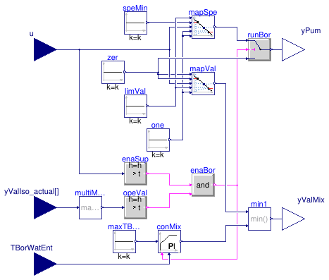
This block implements the control logic for the borefield system.
The main control signal u is yielded by the hot side
or cold side controller, see for instance
Buildings.DHC.ETS.Combined.Controls.SideHot.
The system is enabled when
-
the main control signal is greater than zero,
-
the return position of at least one isolation valve is greater than 90%.
When the system is enabled,
-
the input signal is mapped to modulate in sequence the mixing valve
(from full bypass to closed bypass for a control signal varying between
0% and 30%) and the pump speed (from the minimum to the maximum value
for a control signal varying between 30% and 100%),
-
a PI loop tracks the maximum inlet temperature, the minimum between this
loop output and the previously mapped signal being used to modulate the
valve.
Note that the first control signal for the valve is needed to stabilize
the control of the system when the mass flow rate required to meet
the heat or cold rejection demand is below the flow rate corresponding
to the minimum pump speed.
Parameters
| Type | Name | Default | Description |
|---|
| Real | TBorWatEntMax | | Maximum value of borefield water entering temperature [K] |
| Real | spePumBorMin | 0.1 | Borefield pump minimum speed [1] |
Connectors
| Type | Name | Description |
|---|
| input RealInput | yValIso_actual[2] | Isolation valves return position (fractional) |
| input RealInput | u | Control signal from supervisory |
| output RealOutput | yPum | Control signal for borefield pump [kg/s] |
| output RealOutput | yValMix | Control signal for borefield mixing valve [1] |
| input RealInput | TBorWatEnt | Borefield water entering temperature [K] |
Modelica definition
model Borefield
parameter Real TBorWatEntMax(
final quantity="ThermodynamicTemperature",
final unit="K",
displayUnit="degC")
;
parameter Real spePumBorMin(
final unit="1")=0.1
;
Buildings.Controls.OBC.CDL.Interfaces.RealInput yValIso_actual[2]
;
Buildings.Controls.OBC.CDL.Interfaces.RealInput u
;
Buildings.Controls.OBC.CDL.Interfaces.RealOutput yPum(
final unit="kg/s")
;
Buildings.Controls.OBC.CDL.Interfaces.RealOutput yValMix(
final unit="1")
;
Buildings.Controls.OBC.CDL.Interfaces.RealInput TBorWatEnt(
final unit="K",
displayUnit="degC")
;
Buildings.Controls.OBC.CDL.Reals.PIDWithReset conMix(
final yMin=0,
final yMax=1,
final reverseActing=true,
y_reset=0,
k=0.1,
final controllerType=Buildings.Controls.OBC.CDL.Types.SimpleController.PI,
Ti(displayUnit="s")=120)
;
Buildings.Controls.OBC.CDL.Reals.Sources.Constant maxTBorWatEnt(
y(
final unit="K",
displayUnit="degC"),
final k=TBorWatEntMax)
;
Buildings.Controls.OBC.CDL.Reals.GreaterThreshold opeVal(
final t=0.9,
final h=0.1)
;
Buildings.Controls.OBC.CDL.Reals.MultiMax multiMax1(
final nin=2)
;
Buildings.Controls.OBC.CDL.Reals.GreaterThreshold enaSup(
final t=0.05,
final h=0.025)
;
Buildings.Controls.OBC.CDL.Reals.Switch runBor
;
Buildings.Controls.OBC.CDL.Reals.Sources.Constant limVal(
final k=0.3)
;
Buildings.Controls.OBC.CDL.Reals.Sources.Constant speMin(
final k=spePumBorMin)
;
Buildings.Controls.OBC.CDL.Logical.And enaBor
;
Buildings.Controls.OBC.CDL.Reals.Line mapSpe
;
Buildings.Controls.OBC.CDL.Reals.Sources.Constant one(
final k=1)
;
Buildings.Controls.OBC.CDL.Reals.Sources.Constant zer(
final k=0)
;
Buildings.Controls.OBC.CDL.Reals.Line mapVal
;
Buildings.Controls.OBC.CDL.Reals.Min min1
;
equation
connect(multiMax1.y,opeVal.u);
connect(yValIso_actual,multiMax1.u);
connect(u,enaSup.u);
connect(enaSup.y,enaBor.u1);
connect(opeVal.y,enaBor.u2);
connect(enaBor.y,conMix.trigger);
connect(maxTBorWatEnt.y,conMix.u_s);
connect(runBor.y,yPum);
connect(TBorWatEnt,conMix.u_m);
connect(enaBor.y,runBor.u2);
connect(mapSpe.y,runBor.u1);
connect(u,mapSpe.u);
connect(speMin.y,mapSpe.f1);
connect(min1.y,yValMix);
connect(conMix.y,min1.u2);
connect(mapVal.y,min1.u1);
connect(one.y,mapSpe.x2);
connect(one.y,mapSpe.f2);
connect(one.y,mapVal.f2);
connect(zer.y,mapVal.x1);
connect(limVal.y,mapVal.x2);
connect(u,mapVal.u);
connect(limVal.y,mapSpe.x1);
connect(zer.y,mapVal.f1);
connect(zer.y,runBor.u3);
end Borefield;
Chiller controller
Information
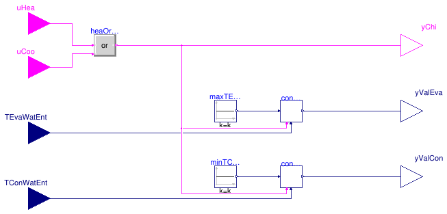
This is a controller for the chiller system, which includes the dedicated
condenser and evaporator pumps.
The system is enabled if any of the input control signals uHea
or uCoo is true.
When enabled,
-
the condenser and evaporator pumps are operated at constant speed, and
-
the condenser (resp. evaporator) mixing valve is modulated with a PI
loop controlling the minimum (resp. maximum) inlet temperature.
Parameters
| Type | Name | Default | Description |
|---|
| Real | TConWatEntMin | | Minimum value of condenser water entering temperature [K] |
| Real | TEvaWatEntMax | | Maximum value of evaporator water entering temperature [K] |
Connectors
| Type | Name | Description |
|---|
| input BooleanInput | uCoo | Cooling enable signal |
| input BooleanInput | uHea | Heating enable signal |
| input RealInput | TConWatEnt | Condenser water entering temperature [K] |
| input RealInput | TEvaWatEnt | Evaporator water entering temperature [K] |
| output RealOutput | yValCon | Condenser mixing valve control signal |
| output RealOutput | yValEva | Evaporator mixing valve control signal |
| output BooleanOutput | yChi | Chiller enable signal |
Modelica definition
model Chiller
parameter Real TConWatEntMin(
final quantity="ThermodynamicTemperature",
final unit="K",
displayUnit="degC")
;
parameter Real TEvaWatEntMax(
final quantity="ThermodynamicTemperature",
final unit="K",
displayUnit="degC")
;
Buildings.Controls.OBC.CDL.Interfaces.BooleanInput uCoo
;
Buildings.Controls.OBC.CDL.Interfaces.BooleanInput uHea
;
Buildings.Controls.OBC.CDL.Interfaces.RealInput TConWatEnt(
final unit="K",
displayUnit="degC")
;
Buildings.Controls.OBC.CDL.Interfaces.RealInput TEvaWatEnt(
final unit="K",
displayUnit="degC")
;
Buildings.Controls.OBC.CDL.Interfaces.RealOutput yValCon
;
Buildings.Controls.OBC.CDL.Interfaces.RealOutput yValEva
;
Buildings.Controls.OBC.CDL.Interfaces.BooleanOutput yChi
;
Buildings.Controls.OBC.CDL.Logical.Or heaOrCoo
;
Buildings.DHC.ETS.Combined.Controls.PIDWithEnable conValEva(
final controllerType=Buildings.Controls.OBC.CDL.Types.SimpleController.PI,
final yMax=1,
final yMin=0,
y_reset=0,
k=0.1,
Ti(
displayUnit="s")=60,
final reverseActing=true)
;
Buildings.DHC.ETS.Combined.Controls.PIDWithEnable conValCon(
final controllerType=Buildings.Controls.OBC.CDL.Types.SimpleController.PI,
final yMax=1,
final yMin=0,
y_reset=0,
k=0.1,
Ti(
displayUnit="s")=60,
final reverseActing=false)
;
Buildings.Controls.OBC.CDL.Reals.Sources.Constant maxTEvaWatEnt(
y(
final unit="K",
displayUnit="degC"),
final k=TEvaWatEntMax)
;
Buildings.Controls.OBC.CDL.Reals.Sources.Constant minTConWatEnt(
y(
final unit="K",
displayUnit="degC"),
final k=TConWatEntMin)
;
equation
connect(TEvaWatEnt,conValEva.u_m);
connect(TConWatEnt,conValCon.u_m);
connect(heaOrCoo.y,yChi);
connect(uHea,heaOrCoo.u1);
connect(uCoo,heaOrCoo.u2);
connect(maxTEvaWatEnt.y,conValEva.u_s);
connect(minTConWatEnt.y,conValCon.u_s);
connect(conValEva.y,yValEva);
connect(heaOrCoo.y,conValEva.uEna);
connect(heaOrCoo.y,conValCon.uEna);
connect(conValCon.y,yValCon);
end Chiller;
District heat exchanger controller
Information
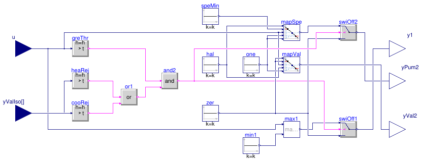
This block implements the control logic for the district heat exchanger,
which realizes the interface between the building system and the district system.
The input signal u is yielded by the supervisory controller, see
Buildings.DHC.ETS.Combined.Controls.Supervisory.
The primary and secondary circuits are enabled to operate if this input signal
is greater than zero and the return position of at least one isolation valve
is greater than 90%.
When enabled,
-
the secondary circuit is controlled based on the input signal
u,
which is mapped to modulate in sequence the mixing valve
(from full bypass to closed bypass for a control signal varying between
0% and 30%) and the pump speed (from the minimum to the maximum value
for a control signal varying between 30% and 100%), and
-
the primary pump speed (or valve opening) is directly modulated with
the input signal
u.
Note that the valve on the secondary side is needed to stabilize the control
of the system when the secondary mass flow rate required to meet the heat or
cold rejection demand is below the flow rate corresponding to the minimum pump speed.
Parameters
| Type | Name | Default | Description |
|---|
| ConnectionConfiguration | conCon | | District connection configuration |
| Real | spePum1Min | 0.1 | Heat exchanger primary pump minimum speed (fractional) [1] |
| Real | spePum2Min | 0.1 | Heat exchanger secondary pump minimum speed (fractional) [1] |
Connectors
| Type | Name | Description |
|---|
| input RealInput | yValIso[2] | Isolation valves return position (index 1 for condenser) |
| output RealOutput | y1 | District heat exchanger primary control signal [1] |
| output RealOutput | yPum2 | District heat exchanger secondary pump control signal [1] |
| output RealOutput | yVal2 | District heat exchanger secondary valve control signal [1] |
| input RealInput | u | Control signal for secondary side (from supervisory) |
Modelica definition
model HeatExchanger
parameter DHC.ETS.Types.ConnectionConfiguration conCon
;
parameter Real spePum1Min(
final unit="1",
min=0)=0.1
;
parameter Real spePum2Min(
final unit="1",
min=0.01)=0.1
;
Buildings.Controls.OBC.CDL.Interfaces.RealInput yValIso[2]
;
Buildings.Controls.OBC.CDL.Interfaces.RealOutput y1(
final unit="1")
;
Buildings.Controls.OBC.CDL.Interfaces.RealOutput yPum2(
final unit="1")
;
Buildings.Controls.OBC.CDL.Interfaces.RealOutput yVal2(
final unit="1")
;
Buildings.Controls.OBC.CDL.Reals.Max max1
;
Buildings.Controls.OBC.CDL.Reals.Switch swiOff1
;
Buildings.Controls.OBC.CDL.Reals.Sources.Constant min1(
final k=
if have_val1
then 0
else spePum1Min)
;
Buildings.Controls.OBC.CDL.Interfaces.RealInput u
;
Buildings.Controls.OBC.CDL.Reals.GreaterThreshold greThr(
final t=0.01,
final h=0.005)
;
Buildings.Controls.OBC.CDL.Logical.And and2
;
Buildings.Controls.OBC.CDL.Reals.GreaterThreshold heaRej(
final t=0.9,
final h=0.1)
;
Buildings.Controls.OBC.CDL.Reals.GreaterThreshold cooRej(
final t=0.9,
final h=0.1)
;
Buildings.Controls.OBC.CDL.Logical.Or or1
;
Buildings.Controls.OBC.CDL.Reals.Sources.Constant speMin(
final k=spePum2Min)
;
Buildings.Controls.OBC.CDL.Reals.Switch swiOff2
;
Buildings.Controls.OBC.CDL.Reals.Line mapSpe
;
Buildings.Controls.OBC.CDL.Reals.Sources.Constant one(
final k=1)
;
Buildings.Controls.OBC.CDL.Reals.Sources.Constant zer(
final k=0)
;
Buildings.Controls.OBC.CDL.Reals.Sources.Constant hal(
final k=0.3)
;
Buildings.Controls.OBC.CDL.Reals.Line mapVal
;
protected
parameter Boolean have_val1=conCon ==
DHC.ETS.Types.ConnectionConfiguration.TwoWayValve
;
equation
connect(swiOff1.y, y1);
connect(max1.y,swiOff1.u1);
connect(u,greThr.u);
connect(greThr.y,and2.u1);
connect(and2.y,swiOff1.u2);
connect(cooRej.y,or1.u2);
connect(heaRej.y,or1.u1);
connect(or1.y,and2.u2);
connect(min1.y,max1.u2);
connect(swiOff2.y,yPum2);
connect(one.y,mapSpe.x2);
connect(one.y,mapSpe.f2);
connect(u,mapSpe.u);
connect(speMin.y,mapSpe.f1);
connect(mapSpe.y,swiOff2.u1);
connect(zer.y,swiOff2.u3);
connect(zer.y,swiOff1.u3);
connect(hal.y,mapSpe.x1);
connect(u,mapVal.u);
connect(zer.y,mapVal.x1);
connect(zer.y,mapVal.f1);
connect(one.y,mapVal.f2);
connect(hal.y,mapVal.x2);
connect(mapVal.y,yVal2);
connect(and2.y,swiOff2.u2);
connect(u, max1.u1);
connect(yValIso[1], heaRej.u);
connect(yValIso[2], cooRej.u);
end HeatExchanger;
PID controller with enable signal
Information
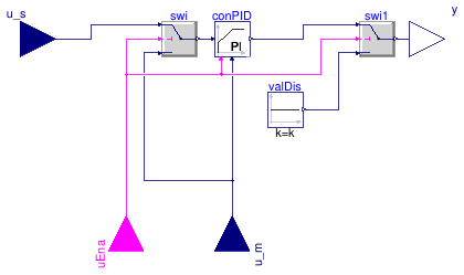
This is an update of
Buildings.Controls.OBC.CDL.Reals.PIDWithReset
with an additional Boolean input representing an enable signal.
-
When enabled, the controller output is identical to
Buildings.Controls.OBC.CDL.Reals.PIDWithReset
(and the controller integral term is reset to
yMin at
enabling time).
-
When disabled, the controller output is zero (and the set point
is replaced by the measurement signal to avoid any
time integration of the control error).
Parameters
| Type | Name | Default | Description |
|---|
| SimpleController | controllerType | Buildings.Controls.OBC.CDL.T... | Type of controller |
| Real | k | 1 | Gain of controller |
| Real | Ti | 0.5 | Time constant of integrator block [s] |
| Real | Td | 0.1 | Time constant of derivative block [s] |
| Real | r | 1 | Typical range of control error, used for scaling the control error |
| Real | yMin | 0 | Lower limit of output |
| Real | yMax | 1 | Upper limit of output |
| Boolean | reverseActing | true | Set to true for reverse acting, or false for direct acting control action |
| Real | y_reset | yMin | Value to which the controller output is reset if the boolean trigger has a rising edge |
| Real | y_neutral | y_reset | Value to which the controller output is reset when the controller is disabled |
Connectors
| Type | Name | Description |
|---|
| input RealInput | u_s | Connector of setpoint input signal |
| input RealInput | u_m | Connector of measurement input signal |
| input BooleanInput | uEna | Enable signal |
| output RealOutput | y | Connector of actuator output signal |
Modelica definition
block PIDWithEnable
parameter Buildings.Controls.OBC.CDL.Types.SimpleController controllerType=Buildings.Controls.OBC.CDL.Types.SimpleController.PI
;
parameter Real k(
min=0)=1
;
parameter Real Ti(
final min=Buildings.Controls.OBC.CDL.Constants.small,
final quantity="Time",
final unit="s") = 0.5
;
parameter Real Td(
final min=Buildings.Controls.OBC.CDL.Constants.small,
final quantity="Time",
final unit="s") = 0.1
;
parameter Real r(
min=100*Buildings.Controls.OBC.CDL.Constants.eps)=1
;
parameter Real yMin=0
;
parameter Real yMax=1
;
parameter Boolean reverseActing=true
;
parameter Real y_reset=yMin
;
parameter Real y_neutral=y_reset
;
Buildings.Controls.OBC.CDL.Interfaces.RealInput u_s
;
Buildings.Controls.OBC.CDL.Interfaces.RealInput u_m
;
Buildings.Controls.OBC.CDL.Interfaces.BooleanInput uEna
;
Buildings.Controls.OBC.CDL.Interfaces.RealOutput y
;
Buildings.Controls.OBC.CDL.Reals.PIDWithReset conPID(
final k=k,
final Ti=Ti,
final Td=Td,
final r=r,
final controllerType=controllerType,
final yMin=yMin,
final yMax=yMax,
final reverseActing=reverseActing,
final y_reset=y_reset)
;
Buildings.Controls.OBC.CDL.Reals.Switch swi
;
Buildings.Controls.OBC.CDL.Reals.Switch swi1
;
Buildings.Controls.OBC.CDL.Reals.Sources.Constant valDis(
final k=y_neutral)
;
equation
connect(conPID.u_s,swi.y);
connect(uEna,swi.u2);
connect(u_s,swi.u1);
connect(u_m,swi.u3);
connect(uEna,conPID.trigger);
connect(u_m,conPID.u_m);
connect(conPID.y,swi1.u1);
connect(swi1.y,y);
connect(uEna,swi1.u2);
connect(valDis.y,swi1.u3);
end PIDWithEnable;
Block that predicts heat exchanger leaving water temperature
Information
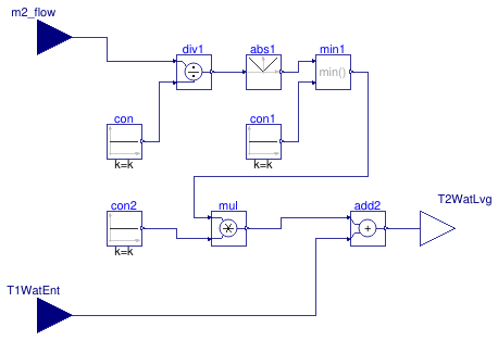
This block computes the predicted heat exchanger leaving water temperature
as used in
Buildings.DHC.ETS.Combined.Controls.WatersideEconomizer.
The predicted heat exchanger approach is computed as
dTApp = dTApp_nominal * m2_flow / m2_flow_nominal,
which gives the predicted heat exchanger leaving water temperature as
T2WatLvg = T1WatEnt + dTApp.
Parameters
| Type | Name | Default | Description |
|---|
| Nominal condition |
| Real | dTApp_nominal | | Heat exchanger approach [K] |
| Real | m2_flow_nominal | | Heat exchanger secondary mass flow rate [kg/s] |
Connectors
| Type | Name | Description |
|---|
| input RealInput | m2_flow | Heat exchanger secondary mass flow rate [kg/s] |
| input RealInput | T1WatEnt | Heat exchanger primary water entering temperature [K] |
| output RealOutput | T2WatLvg | Heat exchanger secondary water leaving temperature [K] |
Modelica definition
model PredictLeavingTemperature
parameter Real dTApp_nominal(
final quantity="TemperatureDifference",
final unit="K")
;
parameter Real m2_flow_nominal(
final quantity="MassFlowRate",
final unit="kg/s")
;
Buildings.Controls.OBC.CDL.Interfaces.RealInput m2_flow(
final unit="kg/s")
;
Buildings.Controls.OBC.CDL.Interfaces.RealInput T1WatEnt(
final unit="K",
displayUnit="degC")
;
Buildings.Controls.OBC.CDL.Interfaces.RealOutput T2WatLvg(
final unit="K",
displayUnit="degC")
;
Buildings.Controls.OBC.CDL.Reals.Divide div1 ;
Buildings.Controls.OBC.CDL.Reals.Sources.Constant con(
final k=m2_flow_nominal)
;
Buildings.Controls.OBC.CDL.Reals.Min min1 ;
Buildings.Controls.OBC.CDL.Reals.Abs abs1 ;
Buildings.Controls.OBC.CDL.Reals.Sources.Constant con1(
final k=1) ;
Buildings.Controls.OBC.CDL.Reals.Sources.Constant con2(
final k=dTApp_nominal)
;
Buildings.Controls.OBC.CDL.Reals.Multiply mul ;
Buildings.Controls.OBC.CDL.Reals.Add add2
;
equation
connect(m2_flow, div1.u1);
connect(con.y, div1.u2);
connect(div1.y, abs1.u);
connect(abs1.y, min1.u1);
connect(con1.y, min1.u2);
connect(con2.y, mul.u2);
connect(min1.y, mul.u1);
connect(mul.y, add2.u1);
connect(T1WatEnt, add2.u2);
connect(add2.y, T2WatLvg);
end PredictLeavingTemperature;
Ideal control of condenser or evaporator variable flow rate
Information
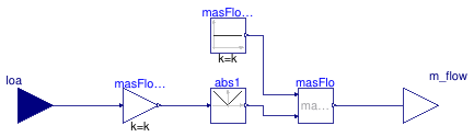
This block implements an ideal control of the evaporator (or condenser) water
mass flow rate.
The control intent aims to maintain a constant water temperature difference
dT_nominal across the heat exchanger, within the limit of a
minimum mass flow rate ratio ratFloMin.
For computational performance and to avoid the use of a PI controller,
the required mass flow rate is computed based on a signal representative of
the load.
Parameters
| Type | Name | Default | Description |
|---|
| Real | Q_flow_nominal | | Heat flow rate at nominal conditions (>0 for condenser) [W] |
| Real | dT_nominal | | DeltaT at nominal conditions (>0 for condenser) [K] |
| Real | ratFloMin | 0.3 | Minimum mass flow rate (ratio to nominal) [1] |
Connectors
| Type | Name | Description |
|---|
| input RealInput | loa | Signal approximating the load on condenser or evaporator [W] |
| output RealOutput | m_flow | Mass flow rate [kg/s] |
Modelica definition
block PrimaryVariableFlow
constant Real cp(
final quantity="SpecificHeatCapacity",
final unit="J/(kg.K)")=Buildings.Utilities.Psychrometrics.Constants.cpWatLiq
;
parameter Real Q_flow_nominal(
final quantity="HeatFlowRate",
final unit="W")
;
parameter Real dT_nominal(
final quantity="TemperatureDifference",
final unit="K",
min=
if Q_flow_nominal > 0
then Buildings.Controls.OBC.CDL.Constants.eps
else -100,
max=
if Q_flow_nominal < 0
then -Buildings.Controls.OBC.CDL.Constants.eps
else 100)
;
parameter Real ratFloMin(
final unit="1",
final min=0,
final max=1)=0.3
;
final parameter Real m_flow_nominal(
final quantity="MassFlowRate",
final unit="kg/s",
final min=0)=
Q_flow_nominal/cp/dT_nominal
;
Buildings.Controls.OBC.CDL.Interfaces.RealInput loa(
final unit="W")
;
Buildings.Controls.OBC.CDL.Interfaces.RealOutput m_flow(
final unit="kg/s")
;
Buildings.Controls.OBC.CDL.Reals.Sources.Constant masFloMin(
final k=ratFloMin*m_flow_nominal)
;
Buildings.Controls.OBC.CDL.Reals.MultiplyByParameter masFlo_dT(
final k=1/cp/dT_nominal)
;
Buildings.Controls.OBC.CDL.Reals.Max masFlo ;
Buildings.Controls.OBC.CDL.Reals.Abs abs1 ;
equation
connect(loa, masFlo_dT.u);
connect(masFloMin.y, masFlo.u1);
connect(masFlo.y, m_flow);
connect(masFlo_dT.y, abs1.u);
connect(abs1.y, masFlo.u2);
end PrimaryVariableFlow;
Supervisory supply temperature reset
Information
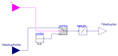
This block implements the supervisory reset of the heating water
supply temperature.
The heating water supply temperature is reset down whenever the
heating demand signal yielded by the building automation system
is false.
This enables operating the chiller at a reduced lift whenever
there is no requirement on the water temperature supplied to the
building system.
Note that the chilled water supply temperature is not reset
for the sake of simplicity. It would indeed require a more
involved algorithm preventing the reset in case it limits
the cold rejection capacity considering the actual
district water temperature.
Parameters
| Type | Name | Default | Description |
|---|
| Real | TWatSupSetMinMax | | Minimum of maximum value of heating or cooling water supply temperature set point [K] |
Connectors
| Type | Name | Description |
|---|
| input BooleanInput | u | Heating or cooling enable signal |
| input RealInput | TWatSupPreSet | Heating or cooling water supply temperature set point [K] |
| output RealOutput | TWatSupSet | Heating or cooling water supply temperature set point after reset [K] |
Modelica definition
Control block for cold side
Information
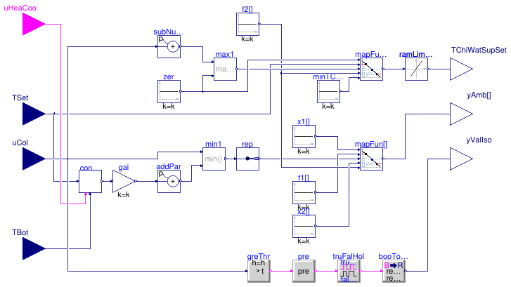
This block serves as the controller for the cold side of the ETS in
Buildings.DHC.ETS.Combined.Controls.Supervisory.
It computes the following control signals.
-
Control signals for ambient sources
yAmb (array)
The cold rejection control signal yielded by the hot side controller
is processed as follows.
-
A controller is used to track the chilled water
supply temperature (CHWST) set point.
This controller is enabled when cooling is enabled.
It yields a control signal value between
0 and nSouAmb.
-
The systems serving as ambient sources are then controlled in sequence
by mapping the minimum between the CHWST control loop output and the
part of the cold rejection signal between
0
and nSouAmb to a nSouAmb-array
of signals between 0 and 1.
-
Chilled water supply temperature set point
TChiWatSupSet
The remaining part of the cold rejection signal between
nSouAmb and nSouAmb+1 is used
to reset the CHWST set point between a maximum value provided
as an input variable, and a minimum value provided as a
parameter.
-
Control signal for the evaporator loop isolation valve
yIsoAmb
The valve is commanded to be fully open whenever the cold rejection control signal
is greater than zero.
The command signal is held for 5 min to avoid short cycling.
Parameters
| Type | Name | Default | Description |
|---|
| Integer | nSouAmb | 1 | Number of ambient sources to control |
| Real | TChiWatSupSetMin | | Minimum value of chilled water supply temperature set point [K] |
| SimpleController | controllerType | Buildings.Controls.OBC.CDL.T... | Type of controller |
| Real | k | 0.1 | Gain of controller |
| Real | Ti | 120 | Time constant of integrator block [s] |
Connectors
| Type | Name | Description |
|---|
| input BooleanInput | uHeaCoo | Enable signal for heating or cooling |
| input RealInput | TSet | Supply temperature set point (heating or chilled water) [K] |
| input RealInput | uCol | Cold rejection control signal |
| input RealInput | TBot | Temperature at bottom of tank [K] |
| output RealOutput | TChiWatSupSet | Chilled water supply temperature set point [K] |
| output RealOutput | yAmb[nSouAmb] | Control signal for ambient sources [1] |
| output RealOutput | yValIso | Ambient loop isolation valve control signal [1] |
Modelica definition
model SideCold
parameter Integer nSouAmb=1
;
parameter Real TChiWatSupSetMin(
final quantity="ThermodynamicTemperature",
final unit="K",
displayUnit="degC")
;
parameter Buildings.Controls.OBC.CDL.Types.SimpleController controllerType=Buildings.Controls.OBC.CDL.Types.SimpleController.PI
;
parameter Real k(
min=0)=0.1
;
parameter Real Ti(
min=Buildings.Controls.OBC.CDL.Constants.small,
final quantity="Time",
final unit="s")=120
;
Buildings.Controls.OBC.CDL.Interfaces.BooleanInput uHeaCoo
;
Buildings.Controls.OBC.CDL.Interfaces.RealInput TSet(
final unit="K",
displayUnit="degC")
;
Buildings.Controls.OBC.CDL.Interfaces.RealInput uCol
;
Buildings.Controls.OBC.CDL.Interfaces.RealInput TBot(
final unit="K",
displayUnit="degC")
;
Buildings.Controls.OBC.CDL.Interfaces.RealOutput TChiWatSupSet(
final unit="K",
displayUnit="degC")
;
Buildings.Controls.OBC.CDL.Interfaces.RealOutput yAmb[nSouAmb](
each final unit="1")
;
Buildings.Controls.OBC.CDL.Interfaces.RealOutput yValIso(
final unit="1")
;
Buildings.Controls.OBC.CDL.Reals.Line mapFun[nSouAmb]
;
Buildings.Controls.OBC.CDL.Reals.Sources.Constant x1[nSouAmb](
final k={(i-1)
for i
in 1:nSouAmb})
;
Buildings.Controls.OBC.CDL.Routing.RealScalarReplicator rep(
final nout=nSouAmb)
;
Buildings.Controls.OBC.CDL.Reals.Sources.Constant f1[nSouAmb](
each final k=0)
;
Buildings.Controls.OBC.CDL.Reals.Sources.Constant f2[nSouAmb](
each final k=1)
;
Buildings.Controls.OBC.CDL.Reals.Sources.Constant x2[nSouAmb](
final k={(i)
for i
in 1:nSouAmb})
;
Buildings.DHC.ETS.Combined.Controls.PIDWithEnable conTChiWatSup(
final k=k,
final Ti=Ti,
final controllerType=Buildings.Controls.OBC.CDL.Types.SimpleController.PI,
final yMin=0,
final yMax=1,
final reverseActing=false)
;
Buildings.Controls.OBC.CDL.Reals.Line mapFunTChiSupSet
;
Buildings.Controls.OBC.CDL.Reals.Sources.Constant minTChiWatSup(
y(
final unit="K",
displayUnit="degC"),
final k=TChiWatSupSetMin)
;
Buildings.Controls.OBC.CDL.Reals.AddParameter addPar(
p=nSouAmb)
;
Buildings.Controls.OBC.CDL.Reals.MultiplyByParameter gai(
k=-nSouAmb)
;
Buildings.Controls.OBC.CDL.Reals.Max max1
;
Buildings.Controls.OBC.CDL.Reals.Sources.Constant zer(
k=0)
;
Buildings.Controls.OBC.CDL.Reals.AddParameter subNumSou(
p=-nSouAmb)
;
Buildings.Controls.OBC.CDL.Reals.Min min1
;
Buildings.Controls.OBC.CDL.Reals.LimitSlewRate ramLimHea(
raisingSlewRate=0.1) ;
Buildings.Controls.OBC.CDL.Conversions.BooleanToReal booToRea
;
Buildings.Controls.OBC.CDL.Reals.GreaterThreshold greThr(
t = 0.01,
h = 0.005)
;
Buildings.Controls.OBC.CDL.Logical.TrueFalseHold truFalHol(
trueHoldDuration=300) ;
Buildings.Controls.OBC.CDL.Logical.Pre pre
;
equation
connect(x1.y,mapFun.x1);
connect(rep.y,mapFun.u);
connect(f1.y,mapFun.f1);
connect(f2.y,mapFun.f2);
connect(x2.y,mapFun.x2);
connect(TSet,conTChiWatSup.u_s);
connect(TBot,conTChiWatSup.u_m);
connect(f2[1].y,mapFunTChiSupSet.x2);
connect(minTChiWatSup.y,mapFunTChiSupSet.f2);
connect(TSet,mapFunTChiSupSet.f1);
connect(uCol,subNumSou.u);
connect(max1.y,mapFunTChiSupSet.u);
connect(uCol,min1.u1);
connect(addPar.y,min1.u2);
connect(min1.y,rep.u);
connect(mapFun.y,yAmb);
connect(ramLimHea.y,TChiWatSupSet);
connect(uHeaCoo,conTChiWatSup.uEna);
connect(zer.y,mapFunTChiSupSet.x1);
connect(uCol,greThr.u);
connect(mapFunTChiSupSet.y,ramLimHea.u);
connect(zer.y,max1.u2);
connect(subNumSou.y,max1.u1);
connect(conTChiWatSup.y, gai.u);
connect(gai.y, addPar.u);
connect(truFalHol.y, booToRea.u);
connect(booToRea.y, yValIso);
connect(greThr.y, pre.u);
connect(pre.y, truFalHol.u);
end SideCold;
Control block for hot side
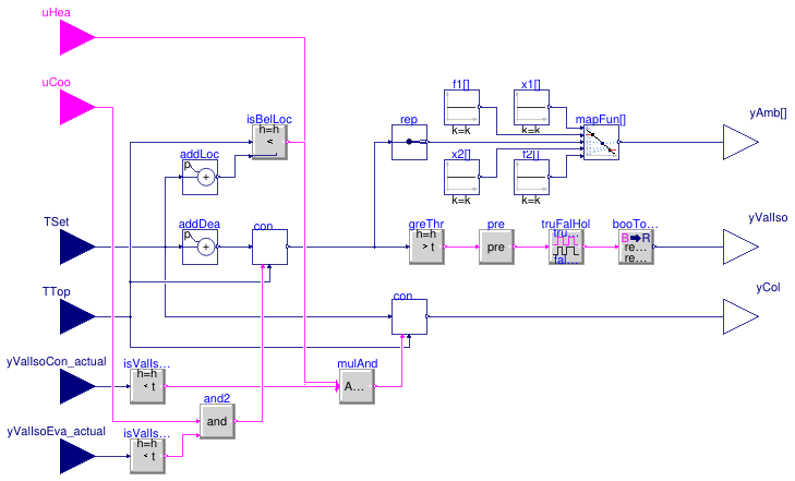
Information
This block serves as the controller for the hot side of the ETS in
Buildings.DHC.ETS.Combined.Controls.Supervisory.
It computes the following control signals.
-
Control signals for ambient sources
yAmb (array)
The controller for heat rejection is enabled when the return position
of the evaporator loop isolation valve is close to zero.
When enabled, it maintains the temperature at the top of the heating water
tank at the heating water supply temperature set point plus a
dead band dTDea.
The controller yields a control signal value between
0 and nSouAmb.
The systems serving as ambient sources are then controlled in sequence
by mapping the controller output to a nSouAmb-array of
signals between 0 and 1.
-
Control signal for cold rejection
yCol
The controller for cold rejection is enabled if
-
the return position of the condenser loop isolation valve is close to zero,
and
-
heating is enabled, and
-
the temperature at the top of the heating water tank is below a safety
limit equal to the heating water supply temperature set point plus the
parameter
dTLoc. This last condition limits the temperature
overshoot after the warmup periods, without having to finely tune the heat and
cold rejection controller parameters to guard against the disturbing effect
of a varying district water temperature.
When enabled, the controller maintains the temperature at the top of the
heating water tank at the heating water supply temperature set point.
The controller yields a signal between 0 and nSouAmb+1
which is connected to
Buildings.DHC.ETS.Combined.Controls.SideCold
where it is used to control in sequence the systems serving as ambient sources
and ultimately to reset down the chilled water supply temperature.
-
Control signal for the condenser loop isolation valve
yIsoAmb
The valve is commanded to be fully open whenever the controller
for heat rejection yields an output signal greater than zero.
The command signal is held for 5 min to avoid short cycling.
Parameters
| Type | Name | Default | Description |
|---|
| Integer | nSouAmb | 1 | Number of ambient sources to control |
| Real | dTDea | 1 | Temperature difference band between set point tracking and heat rejection (absolute value) [K] |
| Real | dTLoc | dTDea + 2 | Temperature difference between set point tracking and cold rejection lockout (absolute value) [K] |
| SimpleController | controllerType | Buildings.Controls.OBC.CDL.T... | Type of controller |
| Real | k | 0.1 | Gain of controller |
| Real | Ti | 120 | Time constant of integrator block [s] |
Connectors
| Type | Name | Description |
|---|
| input BooleanInput | uHea | Enable signal for heating |
| input BooleanInput | uCoo | Enable signal for cooling |
| input RealInput | TSet | Supply temperature set point (heating or chilled water) [K] |
| input RealInput | TTop | Temperature at top of tank [K] |
| input RealInput | yValIsoCon_actual | Return position of condenser to ambient loop isolation valve [1] |
| input RealInput | yValIsoEva_actual | Return position of evaporator to ambient loop isolation valve [1] |
| output RealOutput | yAmb[nSouAmb] | Control signal for ambient sources [1] |
| output RealOutput | yValIso | Ambient loop isolation valve control signal [1] |
| output RealOutput | yCol | Control signal for cold side [1] |
Modelica definition
block SideHot
parameter Integer nSouAmb=1
;
parameter Real dTDea(
final min=0,
final quantity="TemperatureDifference",
final unit="K") = 1
;
parameter Real dTLoc(
final min=0,
final quantity="TemperatureDifference",
final unit="K") = dTDea + 2
;
parameter Buildings.Controls.OBC.CDL.Types.SimpleController controllerType=Buildings.Controls.OBC.CDL.Types.SimpleController.PI
;
parameter Real k(
min=0)=0.1
;
parameter Real Ti(
final min=Buildings.Controls.OBC.CDL.Constants.small,
final quantity="Time",
final unit="s")=120
;
Buildings.Controls.OBC.CDL.Interfaces.BooleanInput uHea
;
Buildings.Controls.OBC.CDL.Interfaces.BooleanInput uCoo
;
Buildings.Controls.OBC.CDL.Interfaces.RealInput TSet(
final unit="K",
displayUnit="degC")
;
Buildings.Controls.OBC.CDL.Interfaces.RealInput TTop(
final unit="K",
displayUnit="degC")
;
Buildings.Controls.OBC.CDL.Interfaces.RealInput yValIsoCon_actual(
final unit="1")
;
Buildings.Controls.OBC.CDL.Interfaces.RealInput yValIsoEva_actual(
final unit="1")
;
Buildings.Controls.OBC.CDL.Interfaces.RealOutput yAmb[nSouAmb](
each final unit="1")
;
Buildings.Controls.OBC.CDL.Interfaces.RealOutput yValIso(
final unit="1")
;
Buildings.Controls.OBC.CDL.Interfaces.RealOutput yCol(
final unit="1")
;
Buildings.DHC.ETS.Combined.Controls.PIDWithEnable conColRej(
final k=k,
final Ti=Ti,
final controllerType=Buildings.Controls.OBC.CDL.Types.SimpleController.PI,
final yMin=0,
final yMax=nSouAmb+1,
final reverseActing=true)
;
Buildings.Controls.OBC.CDL.Reals.GreaterThreshold greThr(
final t = 0.01,
final h = 0.005)
;
Buildings.Controls.OBC.CDL.Conversions.BooleanToReal booToRea
;
Buildings.DHC.ETS.Combined.Controls.PIDWithEnable conHeaRej(
final k=k,
final Ti=Ti,
final controllerType=Buildings.Controls.OBC.CDL.Types.SimpleController.PI,
final yMin=0,
final yMax=nSouAmb,
final reverseActing=false)
;
Buildings.Controls.OBC.CDL.Reals.Line mapFun[nSouAmb]
;
Buildings.Controls.OBC.CDL.Reals.Sources.Constant x1[nSouAmb](
final k={(i-1)
for i
in 1:nSouAmb})
;
Buildings.Controls.OBC.CDL.Routing.RealScalarReplicator rep(
final nout=nSouAmb)
;
Buildings.Controls.OBC.CDL.Reals.Sources.Constant f1[nSouAmb](
each final k=0)
;
Buildings.Controls.OBC.CDL.Reals.Sources.Constant f2[nSouAmb](
each final k=1)
;
Buildings.Controls.OBC.CDL.Reals.Sources.Constant x2[nSouAmb](
final k={(i)
for i
in 1:nSouAmb})
;
Buildings.Controls.OBC.CDL.Reals.LessThreshold isValIsoConClo(
final t=0.01,
h=0.005)
;
Buildings.Controls.OBC.CDL.Reals.LessThreshold isValIsoEvaClo(
final t=0.01,
h=0.005)
;
Buildings.Controls.OBC.CDL.Logical.MultiAnd mulAnd(
nin=3);
Buildings.Controls.OBC.CDL.Reals.AddParameter addDea(
p=dTDea)
;
Buildings.Controls.OBC.CDL.Reals.AddParameter addLoc(
p=dTLoc)
;
Buildings.Controls.OBC.CDL.Reals.Less isBelLoc(
h=0.1)
;
Buildings.Controls.OBC.CDL.Logical.TrueFalseHold truFalHol(
trueHoldDuration=300) ;
Buildings.Controls.OBC.CDL.Logical.Pre pre
;
Buildings.Controls.OBC.CDL.Logical.And and2
;
equation
connect(mapFun.y,yAmb);
connect(TSet,conColRej.u_s);
connect(TTop,conColRej.u_m);
connect(conHeaRej.y,greThr.u);
connect(x1.y,mapFun.x1);
connect(conHeaRej.y,rep.u);
connect(rep.y,mapFun.u);
connect(f1.y,mapFun.f1);
connect(f2.y,mapFun.f2);
connect(x2.y,mapFun.x2);
connect(conColRej.y,yCol);
connect(TTop,conHeaRej.u_m);
connect(yValIsoCon_actual,isValIsoConClo.u);
connect(yValIsoEva_actual,isValIsoEvaClo.u);
connect(mulAnd.y,conColRej.uEna);
connect(TSet,addDea.u);
connect(addDea.y,conHeaRej.u_s);
connect(TSet,addLoc.u);
connect(TTop,isBelLoc.u1);
connect(addLoc.y,isBelLoc.u2);
connect(uHea, mulAnd.u[1]);
connect(isValIsoConClo.y,mulAnd.u[2]);
connect(isBelLoc.y,mulAnd.u[3]);
connect(truFalHol.y, booToRea.u);
connect(booToRea.y, yValIso);
connect(greThr.y, pre.u);
connect(pre.y, truFalHol.u);
connect(isValIsoEvaClo.y, and2.u2);
connect(and2.y, conHeaRej.uEna);
connect(and2.u1, uCoo);
end SideHot;
Supervisory controller
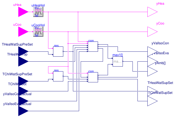
Information
This block implements the supervisory control functions of the ETS model
Buildings.DHC.ETS.Combined.ChillerBorefield.
-
Heating (resp. cooling) is enabled based on the input signal
uHea
(resp. uCoo) which is held for 15', meaning that,
when enabled, the mode remains active for at least 15 minutes and,
when disabled, the mode cannot be enabled again for at least 15 minutes.
The heating and cooling enable signals should be computed externally based on a schedule
(to lock out the system during off-hours), ideally in conjunction with the number
of requests yielded by the terminal unit controllers, or any
other signal representative of the load.
Indeed, the heating water supply set point is allowed to be reset down
only when heating is disabled, in which
case the system performance is improved due to a lower chiller lift.
-
The controller resets the heating water supply temperature based on the logic described in
Buildings.DHC.ETS.Combined.Controls.Reset.
Note that this resetting logic is meant to operate the chiller at low lift.
The chilled water supply temperature may be also reset down by
Buildings.DHC.ETS.Combined.Controls.SideCold
to maintain the heating water supply temperature set point.
This second resetting logic is required for the heating function of the unit,
but it has a negative impact on the lift.
-
Eventually the systems serving as ambient sources are controlled based on the
maximum of the control signals
yAmb yielded by
Buildings.DHC.ETS.Combined.Controls.SideHot
and
Buildings.DHC.ETS.Combined.Controls.SideCold.
Extends from Buildings.DHC.ETS.Combined.Controls.BaseClasses.PartialSupervisory (Partial model for supervisory controller).
Parameters
| Type | Name | Default | Description |
|---|
| Integer | nSouAmb | | Number of ambient sources to control |
| SimpleController | controllerType | Buildings.Controls.OBC.CDL.T... | Type of controller |
| Real | kHot | 0.05 | Gain of controller on hot side |
| Real | kCol | 0.1 | Gain of controller on cold side |
| Real | TiHot | 300 | Time constant of integrator block on hot side [s] |
| Real | TiCol | 120 | Time constant of integrator block on cold side [s] |
| Real | THeaWatSupSetMin | | Minimum value of heating water supply temperature set point [K] |
| Real | TChiWatSupSetMin | | Minimum value of chilled water supply temperature set point [K] |
| Real | TChiWatSupSetMax | | Maximum value of chilled water supply temperature set point [K] |
Connectors
| Type | Name | Description |
|---|
| input BooleanInput | uHea | Heating enable signal |
| input BooleanInput | uCoo | Cooling enable signal |
| input RealInput | TChiWatSupPreSet | Chilled water supply temperature set point [K] |
| input RealInput | TChiWatBot | Chilled water temperature at tank bottom [K] |
| input RealInput | THeaWatTop | Heating water temperature at tank top [K] |
| input RealInput | THeaWatSupPreSet | Heating water supply temperature set point [K] |
| output RealOutput | THeaWatSupSet | Heating water supply temperature set point after reset [K] |
| output RealOutput | TChiWatSupSet | Chilled water supply temperature set point after reset [K] |
| output RealOutput | yValIsoEva | Evaporator to ambient loop isolation valve control signal [1] |
| output RealOutput | yValIsoCon | Condenser to ambient loop isolation valve control signal [1] |
| output RealOutput | yAmb[nSouAmb] | Control output for ambient sources [1] |
| output BooleanOutput | yHea | Tank in heating demand |
| output BooleanOutput | yCoo | Tank in cooling demand |
| input RealInput | yValIsoCon_actual | Return position of condenser to ambient loop isolation valve [1] |
| input RealInput | yValIsoEva_actual | Return position of evaporator to ambient loop isolation valve [1] |
Modelica definition
model Supervisory
extends Buildings.DHC.ETS.Combined.Controls.BaseClasses.PartialSupervisory;
parameter Buildings.Controls.OBC.CDL.Types.SimpleController
controllerType=Buildings.Controls.OBC.CDL.Types.SimpleController.PI
;
parameter Real kHot(
min=0)=0.05
;
parameter Real kCol(
min=0)=0.1
;
parameter Real TiHot(
final min=Buildings.Controls.OBC.CDL.Constants.small,
final quantity="Time",
final unit="s") = 300
;
parameter Real TiCol(
final min=Buildings.Controls.OBC.CDL.Constants.small,
final quantity="Time",
final unit="s") = 120
;
parameter Real THeaWatSupSetMin(
final quantity="ThermodynamicTemperature",
final unit="K",
displayUnit="degC")
;
parameter Real TChiWatSupSetMin(
final quantity="ThermodynamicTemperature",
final unit="K",
displayUnit="degC")
;
parameter Real TChiWatSupSetMax(
final quantity="ThermodynamicTemperature",
final unit="K",
displayUnit="degC")
;
Buildings.Controls.OBC.CDL.Interfaces.RealInput yValIsoCon_actual(
final unit="1")
;
Buildings.Controls.OBC.CDL.Interfaces.RealInput yValIsoEva_actual(
final unit="1")
;
Buildings.DHC.ETS.Combined.Controls.SideHot conHot(
final k=kHot,
final Ti=TiHot,
final nSouAmb=nSouAmb,
final controllerType=controllerType)
;
Buildings.DHC.ETS.Combined.Controls.SideCold conCol(
final k=kCol,
final Ti=TiCol,
final nSouAmb=nSouAmb,
final controllerType=controllerType,
final TChiWatSupSetMin=TChiWatSupSetMin)
;
Buildings.Controls.OBC.CDL.Reals.Max max1[nSouAmb]
;
Buildings.DHC.ETS.Combined.Controls.Reset resTHeaSup(
final TWatSupSetMinMax=THeaWatSupSetMin)
;
Buildings.DHC.ETS.Combined.Controls.Reset resTCooSup(
final TWatSupSetMinMax=TChiWatSupSetMax)
;
equation
connect(conHot.yAmb,max1.u1);
connect(conCol.yAmb,max1.u2);
connect(conHot.yCol,conCol.uCol);
connect(resTHeaSup.TWatSupSet, conHot.TSet);
connect(THeaWatTop,conHot.TTop);
connect(max1.y,yAmb);
connect(TChiWatBot,conCol.TBot);
connect(THeaWatSupPreSet, resTHeaSup.TWatSupPreSet);
connect(conHot.yValIso,yValIsoCon);
connect(conCol.yValIso,yValIsoEva);
connect(resTHeaSup.TWatSupSet, THeaWatSupSet);
connect(conCol.TChiWatSupSet,TChiWatSupSet);
connect(uHeaHol.y, conHot.uHea);
connect(uCooHol.y,conCol.uHeaCoo);
connect(uHeaHol.y, resTHeaSup.u);
connect(uHeaHol.y,yHea);
connect(uCooHol.y,yCoo);
connect(yValIsoCon_actual,conHot.yValIsoCon_actual);
connect(yValIsoEva_actual,conHot.yValIsoEva_actual);
connect(conHot.uCoo, uCooHol.y);
connect(TChiWatSupPreSet, resTCooSup.TWatSupPreSet);
connect(uCooHol.y, resTCooSup.u);
connect(resTCooSup.TWatSupSet, conCol.TSet);
end Supervisory;
Controller for flow switch box
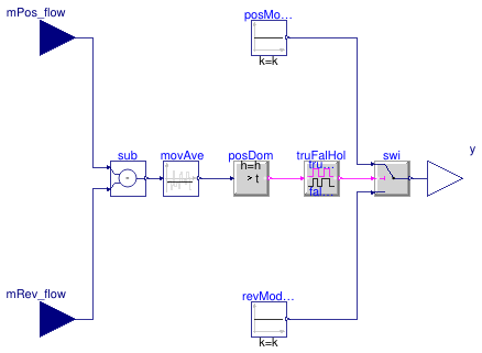
Information
This block implements a control logic preventing flow reversal in the
service line, for instance with the hydronic configuration of
Buildings.DHC.ETS.Combined.HeatPumpHeatExchanger.
The block requires two input signals representing the mass flow rate contributing
to a positive flow direction mPos_flow and the mass flow contributing
to a reverse flow direction mRev_flow.
The output signal y switches to maintain mPos_flow ≥ mRev_flow
with a temporization avoiding short cycling.
Due to the temporization, the mass flow rate may transiently change direction as
illustrated in
Buildings.DHC.ETS.Combined.Subsystems.Validation.SwitchBox.
Parameters
| Type | Name | Default | Description |
|---|
| Real | trueHoldDuration | | true hold duration [s] |
| Real | falseHoldDuration | trueHoldDuration | false hold duration [s] |
| Nominal condition |
| Real | m_flow_nominal | | Nominal mass flow rate, used for scaling to avoid chattering [kg/s] |
Connectors
| Type | Name | Description |
|---|
| input RealInput | mPos_flow | Service water mass flow rate in positive direction [kg/s] |
| input RealInput | mRev_flow | Service water mass flow rate in reverse direction [kg/s] |
| output RealOutput | y | Control output signal [1] |
Modelica definition
block SwitchBox
parameter Real m_flow_nominal(
final quantity="MassFlowRate",
final unit="kg/s")
;
parameter Real trueHoldDuration(
final quantity="Time",
final unit="s")
;
parameter Real falseHoldDuration(
final quantity="Time",
final unit="s") = trueHoldDuration
;
Buildings.Controls.OBC.CDL.Interfaces.RealInput mPos_flow(
final unit="kg/s")
;
Buildings.Controls.OBC.CDL.Interfaces.RealInput mRev_flow(
final unit="kg/s")
;
Buildings.Controls.OBC.CDL.Interfaces.RealOutput y(
final unit="1")
;
Buildings.Controls.OBC.CDL.Reals.GreaterThreshold posDom(
final h=0.001*m_flow_nominal)
;
Buildings.Controls.OBC.CDL.Reals.Switch swi
;
Buildings.Controls.OBC.CDL.Reals.Sources.Constant posModOn(
final k=1)
;
Buildings.Controls.OBC.CDL.Logical.TrueFalseHold truFalHol(
final trueHoldDuration=trueHoldDuration,
final falseHoldDuration=falseHoldDuration)
;
Buildings.Controls.OBC.CDL.Reals.Sources.Constant revModOn(
final k=0)
;
Buildings.Controls.OBC.CDL.Reals.Subtract sub
;
Buildings.Controls.OBC.CDL.Reals.MovingAverage movAve(
final delta=trueHoldDuration/10)
;
equation
connect(posModOn.y, swi.u1);
connect(swi.y, y);
connect(posDom.y, truFalHol.u);
connect(truFalHol.y, swi.u2);
connect(revModOn.y, swi.u3);
connect(mPos_flow, sub.u1);
connect(mRev_flow, sub.u2);
connect(posDom.u, movAve.y);
connect(movAve.u, sub.y);
end SwitchBox;
Waterside economizer controller
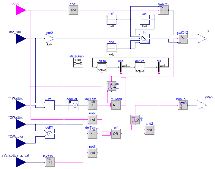
Information
This block implements the control logic for the waterside economizer.
The system is enabled if
-
it has been disabled for more than 20 minutes, and
-
the "cooling enabled" input signal is
true, and
-
the evaporator isolation valve is closed (i.e., the system is not in cold
rejection mode), and
-
the predicted leaving water temperature is lower than the entering water
temperature minus
dTEna.
The system is disabled if
-
it has been enabled for more than 20 minutes, and
-
the "cooling enabled" input signal is
false, or
-
the evaporator isolation valve is open, or
-
the leaving water temperature is higher than the entering water
temperature minus
dTDis.
When the system is enabled
-
the primary side is controlled so that the primary flow rate
varies linearly with the secondary flow rate, and
-
the bypass valve on the secondary side is fully closed.
When the system is disabled
-
if the "cooling enabled" input signal is
true and
the evaporator isolation valve is closed,
the primary pump (resp. valve) is operated at its minimum speed
(resp. opening), otherwise it is switched off (resp. fully closed):
this is needed to yield a representative measurement of the
service water entering temperature, and
-
the bypass valve on the secondary side is fully open.
Parameters
| Type | Name | Default | Description |
|---|
| Nominal condition |
| Real | m2_flow_nominal | | Heat exchanger secondary mass flow rate [kg/s] |
| Real | T_a1_nominal | | Nominal water inlet temperature on district side [K] |
| Real | T_b2_nominal | | Nominal water outlet temperature on building side [K] |
| Controls |
| Real | y1Min | 0.05 | Minimum pump flow rate or valve opening for temperature measurement (fractional) [1] |
| Real | dTEna | 1 | Minimum delta-T above predicted heat exchanger leaving water temperature to enable WSE [K] |
| Real | dTDis | 0.5 | Minimum delta-T across heat exchanger before disabling WSE [K] |
Connectors
| Type | Name | Description |
|---|
| input BooleanInput | uCoo | Cooling enable signal |
| input RealInput | m2_flow | Heat exchanger secondary mass flow rate [kg/s] |
| input RealInput | T1WatEnt | Heat exchanger primary water entering temperature [K] |
| input RealInput | T2WatEnt | Heat exchanger secondary water entering temperature [K] |
| input RealInput | T2WatLvg | Heat exchanger secondary water leaving temperature [K] |
| input RealInput | yValIsoEva_actual | Return position of evaporator to ambient loop isolation valve [1] |
| output RealOutput | y1 | Primary control signal (pump or valve) [1] |
| output RealOutput | yVal2 | Secondary valve control signal [1] |
Modelica definition
model WatersideEconomizer
parameter Real m2_flow_nominal(
final quantity="MassFlowRate",
final unit="kg/s")
;
parameter Real T_a1_nominal(
final unit="K",
displayUnit="degC",
final quantity="ThermodynamicTemperature")
;
parameter Real T_b2_nominal(
final unit="K",
displayUnit="degC",
final quantity="ThermodynamicTemperature")
;
parameter Real y1Min(
final unit="1")=0.05
;
parameter Real dTEna(
final quantity="TemperatureDifference",
final unit="K")=1
;
parameter Real dTDis(
final quantity="TemperatureDifference",
final unit="K")=0.5
;
Buildings.Controls.OBC.CDL.Interfaces.BooleanInput uCoo
;
Buildings.Controls.OBC.CDL.Interfaces.RealInput m2_flow(
final unit="kg/s")
;
Buildings.Controls.OBC.CDL.Interfaces.RealInput T1WatEnt(
final unit="K",
displayUnit="degC")
;
Buildings.Controls.OBC.CDL.Interfaces.RealInput T2WatEnt(
final unit="K",
displayUnit="degC")
;
Buildings.Controls.OBC.CDL.Interfaces.RealInput T2WatLvg(
final unit="K",
displayUnit="degC")
;
Buildings.Controls.OBC.CDL.Interfaces.RealInput yValIsoEva_actual(
final unit="1")
;
Buildings.Controls.OBC.CDL.Interfaces.RealOutput y1(
final unit="1")
;
Buildings.Controls.OBC.CDL.Interfaces.RealOutput yVal2(
final unit="1")
;
Buildings.Controls.OBC.CDL.Reals.AddParameter addDelTem(
final p=dTEna)
;
Modelica.StateGraph.InitialStepWithSignal iniSta(nIn=1, nOut=1)
;
Modelica.StateGraph.TransitionWithSignal ena ;
Modelica.StateGraph.StepWithSignal actSta(nIn=1, nOut=1)
;
Modelica.StateGraph.TransitionWithSignal dis
;
Buildings.Controls.OBC.CDL.Reals.Subtract delT1
;
Buildings.Controls.OBC.CDL.Reals.LessThreshold delTemDis(
final t = dTDis,
final h = 0.05)
;
Buildings.DHC.ETS.Combined.Controls.PredictLeavingTemperature calTemLvg(
final dTApp_nominal=
abs(T_a1_nominal - T_b2_nominal),
final m2_flow_nominal=m2_flow_nominal)
;
Buildings.Controls.OBC.CDL.Reals.Less delTemDis1(
final h = 0.05)
;
Buildings.Controls.OBC.CDL.Conversions.BooleanToReal booToRea(
final realTrue=1,
final realFalse=0)
;
inner Modelica.StateGraph.StateGraphRoot stateGraphRoot ;
Buildings.Controls.OBC.CDL.Reals.Sources.Constant min1(
final k=y1Min)
;
Buildings.Controls.OBC.CDL.Reals.Line lin
;
Buildings.Controls.OBC.CDL.Reals.Switch swiOff1
;
Buildings.Controls.OBC.CDL.Reals.Sources.Constant zer(
final k=0) ;
Buildings.Controls.OBC.CDL.Logical.MultiAnd mulAnd(nin=4)
;
Buildings.Controls.OBC.CDL.Logical.MultiOr or1(nin=3)
;
Buildings.Controls.OBC.CDL.Logical.Not not2 ;
Buildings.Controls.OBC.CDL.Logical.Timer tim(t=1200)
;
Buildings.Controls.OBC.CDL.Logical.Timer tim1(t=1200)
;
Buildings.Controls.OBC.CDL.Logical.And and2
;
Buildings.Controls.OBC.CDL.Reals.LessThreshold isValIsoEvaClo(
final t=0.01,
h=0.005)
;
Buildings.Controls.OBC.CDL.Logical.Not not1 ;
Buildings.Controls.OBC.CDL.Logical.And and1
;
Buildings.Controls.OBC.CDL.Reals.MultiplyByParameter nor2(
final k=1/m2_flow_nominal) ;
Buildings.Controls.OBC.CDL.Reals.Switch swiOff2
;
Buildings.Controls.OBC.CDL.Reals.Sources.Constant one(
final k=1) ;
equation
connect(T2WatEnt, delT1.u1);
connect(T2WatLvg, delT1.u2);
connect(delT1.y, delTemDis.u);
connect(T1WatEnt, calTemLvg.T1WatEnt);
connect(calTemLvg.T2WatLvg, addDelTem.u);
connect(addDelTem.y, delTemDis1.u1);
connect(T2WatEnt, delTemDis1.u2);
connect(iniSta.outPort[1], ena.inPort);
connect(ena.outPort, actSta.inPort[1]);
connect(actSta.outPort[1], dis.inPort);
connect(dis.outPort, iniSta.inPort[1]);
connect(booToRea.y, yVal2);
connect(zer.y, swiOff1.u3);
connect(mulAnd.y, ena.condition);
connect(uCoo, not2.u);
connect(actSta.active, booToRea.u);
connect(delTemDis1.y, mulAnd.u[1]);
connect(iniSta.active, tim1.u);
connect(tim1.passed, mulAnd.u[2]);
connect(uCoo, mulAnd.u[3]);
connect(actSta.active, tim.u);
connect(tim.passed, and2.u1);
connect(or1.y, and2.u2);
connect(and2.y, dis.condition);
connect(m2_flow, calTemLvg.m2_flow);
connect(yValIsoEva_actual,isValIsoEvaClo.u);
connect(isValIsoEvaClo.y, mulAnd.u[4]);
connect(isValIsoEvaClo.y, not1.u);
connect(delTemDis.y, or1.u[1]);
connect(not2.y, or1.u[2]);
connect(not1.y, or1.u[3]);
connect(uCoo, and1.u1);
connect(and1.y, swiOff1.u2);
connect(isValIsoEvaClo.y, and1.u2);
connect(m2_flow, nor2.u);
connect(min1.y, swiOff1.u1);
connect(swiOff2.y, y1);
connect(swiOff1.y, swiOff2.u1);
connect(iniSta.active, swiOff2.u2);
connect(lin.y, swiOff2.u3);
connect(nor2.y, lin.u);
connect(one.y, lin.x2);
connect(one.y, lin.f2);
connect(zer.y, lin.x1);
connect(min1.y, lin.f1);
end WatersideEconomizer;
 Buildings.DHC.ETS.Combined.Controls.Borefield
 Buildings.DHC.ETS.Combined.Controls.Chiller
 Buildings.DHC.ETS.Combined.Controls.HeatExchanger
 Buildings.DHC.ETS.Combined.Controls.PIDWithEnable
 Buildings.DHC.ETS.Combined.Controls.PredictLeavingTemperature
 Buildings.DHC.ETS.Combined.Controls.PrimaryVariableFlow
 Buildings.DHC.ETS.Combined.Controls.Reset
 Buildings.DHC.ETS.Combined.Controls.SideCold
 Buildings.DHC.ETS.Combined.Controls.SideHot
 Buildings.DHC.ETS.Combined.Controls.Supervisory
 Buildings.DHC.ETS.Combined.Controls.SwitchBox
 Buildings.DHC.ETS.Combined.Controls.WatersideEconomizer