Buildings.Controls.OBC.CDL.Reals
Package with blocks for continuous variables
Information
Package with blocks for elementary mathematical functions for continuous variables.
Package Content
| Name | Description |
|---|---|
| Output the absolute value of the input | |
| Output the arc cosine of the input | |
| Output the sum of the two inputs | |
| Output the sum of an input plus a parameter | |
| Output the arc sine of the input | |
| Output the arc tangent of the input | |
| Output atan(u1/u2) of the inputs u1 and u2 | |
| Output the average of its two inputs | |
| Output the cosine of the input | |
| Block that approximates the derivative of the input | |
| Output first input divided by second input | |
| Output the exponential (base e) of the input | |
| Output y is true, if input u1 is greater than input u2 with hysteresis | |
| Output y is true, if input u is greater than threshold with hysteresis | |
| Transform Real to Boolean signal with Hysteresis | |
| Output the integral of the input signal | |
| Output y is true, if input u1 is less than input u2 | |
| Output y is true, if input u is less than threshold with hysteresis | |
| Limit the increase or decrease rate of input | |
| Limit the range of a signal | |
| Output the value of the input x along a line specified by two points | |
| Output the natural (base e) logarithm of the input (input > 0 required) | |
| Output the base 10 logarithm of the input (input > 0 required) | |
| Output the product of a gain matrix with the input signal vector | |
| Output vector of row- or column-wise maximum of the input matrix | |
| Output vector of row- or column-wise minimum values | |
| Pass through the largest signal | |
| Pass through the smallest signal | |
| Output the remainder of first input divided by second input (~=0) | |
| Block to output moving average | |
| Output the maximum element of the input vector | |
| Output the minimum element of the input vector | |
| Sum of Reals, y = k[1]*u[1] + k[2]*u[2] + ... + k[n]*u[n] | |
| Output product of the two inputs | |
| Output the product of a gain value with the input signal | |
| P, PI, PD, and PID controller | |
| P, PI, PD, and PID controller with output reset | |
| Limit the changing rate of the input | |
| Round real number to given digits | |
| Output the sine of the input | |
| Sort elements of input vector in ascending or descending order | |
| Output the square root of the input (input >= 0 required) | |
| Output the difference of the two inputs | |
| Switch between two Real signals | |
| Output the tangent of the input | |
| Package with blocks that generate source signals | |
| Collection of models that validate the continuous blocks of the CDL |
 Buildings.Controls.OBC.CDL.Reals.Abs
Output the absolute value of the input
Information
Block that outputs y = abs(u),
where
u is an input.
Connectors
| Type | Name | Description |
|---|---|---|
| input RealInput | u | Input for absolute function |
| output RealOutput | y | Absolute value of the input |
Modelica definition
 Buildings.Controls.OBC.CDL.Reals.Acos
Output the arc cosine of the input
Information
Block that outputs y = acos(u), where u is an input.
Connectors
| Type | Name | Description |
|---|---|---|
| input RealInput | u | Input for arc cosine function |
| output RealOutput | y | Arc cosine of the input [rad] |
Modelica definition
 Buildings.Controls.OBC.CDL.Reals.Add
Output the sum of the two inputs
Information
Block that outputs y as the sum of the
two input signals u1 and u2,
y = u1 + u2.
Connectors
| Type | Name | Description |
|---|---|---|
| input RealInput | u1 | Input to be added |
| input RealInput | u2 | Input to be added |
| output RealOutput | y | Sum of the inputs |
Modelica definition
 Buildings.Controls.OBC.CDL.Reals.AddParameter
Output the sum of an input plus a parameter
Information
Block that outputs y = u + p,
where p is parameter and u is an input.
Parameters
| Type | Name | Default | Description |
|---|---|---|---|
| Real | p | Parameter to be added to the input |
Connectors
| Type | Name | Description |
|---|---|---|
| input RealInput | u | Input to be added to the parameter |
| output RealOutput | y | Sum of the parameter and the input |
Modelica definition
 Buildings.Controls.OBC.CDL.Reals.Asin
Output the arc sine of the input
Information
Block that outputs y = asin(u), where u is an input.
Connectors
| Type | Name | Description |
|---|---|---|
| input RealInput | u | Input for the arc sine function |
| output RealOutput | y | Arc sin of the input [rad] |
Modelica definition
 Buildings.Controls.OBC.CDL.Reals.Atan
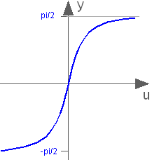
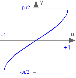
Output the arc tangent of the input
Information
Block that outputs y = atan(u), where u is an input.
Connectors
| Type | Name | Description |
|---|---|---|
| input RealInput | u | Input for the arc tangent function |
| output RealOutput | y | Arc tangent of the input [rad] |
Modelica definition
 Buildings.Controls.OBC.CDL.Reals.Atan2
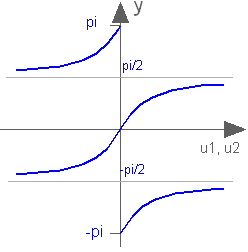
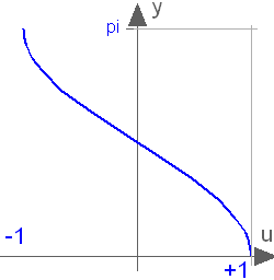
Output atan(u1/u2) of the inputs u1 and u2
Information
Block that outputs the tangent-inverse y = atan2(u1, u2)
of the input u1 divided by the input u2.
u1 and u2 shall not be zero at the same time instant.
Atan2 uses the sign of u1 and u2
in order to construct the solution in the range
-π ≤ y ≤ π, whereas
Buildings.Controls.OBC.CDL.Reals.Atan
gives a solution in the range
-π/2 ≤ y ≤ π/2.
Connectors
| Type | Name | Description |
|---|---|---|
| input RealInput | u1 | Input u1 for the atan2(u1/u2) function |
| input RealInput | u2 | Input u2 for the atan2(u1/u2) function |
| output RealOutput | y | Output with atan2(u1/u2) [rad] |
Modelica definition
 Buildings.Controls.OBC.CDL.Reals.Average
Output the average of its two inputs
Information
Block that outputs y = (u1 + u2) / 2,
where
u1 and u2 are inputs.
Connectors
| Type | Name | Description |
|---|---|---|
| input RealInput | u1 | Input for average function |
| input RealInput | u2 | Input for average function |
| output RealOutput | y | Output with the average of the two inputs |
Modelica definition
 Buildings.Controls.OBC.CDL.Reals.Cos
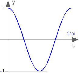
Output the cosine of the input
Information
Block that outputs y = cos(u),
where
u is an input.
Connectors
| Type | Name | Description |
|---|---|---|
| input RealInput | u | Input for the cosine function [rad] |
| output RealOutput | y | Cosine of the input |
Modelica definition
 Buildings.Controls.OBC.CDL.Reals.Derivative
Block that approximates the derivative of the input
Information
This blocks defines the transfer function between the
input u and the output y
as approximated derivative:
                s
  y = k * ------------ * u
            T * s + 1
If k=0, the block reduces to y=0.
Parameters
| Type | Name | Default | Description |
|---|---|---|---|
| Initialization | |||
| Real | y_start | 0 | Initial value of output (= state) |
Connectors
| Type | Name | Description |
|---|---|---|
| input RealInput | k | Input for the gain |
| input RealInput | T | Input for the time constant (T>0 required; T=0 is ideal derivative block) [s] |
| input RealInput | u | Input to be differentiated |
| output RealOutput | y | Approximation of derivative du/dt |
Modelica definition
 Buildings.Controls.OBC.CDL.Reals.Divide
Output first input divided by second input
Information
Block that outputs y = u1 / u2,
where
u1 and u2 are inputs.
Connectors
| Type | Name | Description |
|---|---|---|
| input RealInput | u1 | Input for dividend |
| input RealInput | u2 | Input for divisor |
| output RealOutput | y | Output with the quotient |
Modelica definition
 Buildings.Controls.OBC.CDL.Reals.Exp
Output the exponential (base e) of the input
Information
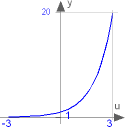
Block that outputs y = exp(u),
where
u is an input and exp() is the
base-e exponential function.
Connectors
| Type | Name | Description |
|---|---|---|
| input RealInput | u | Input for the base e exponential function |
| output RealOutput | y | Base e exponential value of the input |
Modelica definition
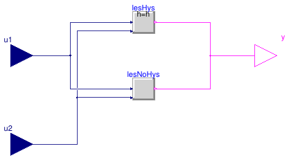
 Buildings.Controls.OBC.CDL.Reals.Greater
Output y is true, if input u1 is greater than input u2 with hysteresis
Information
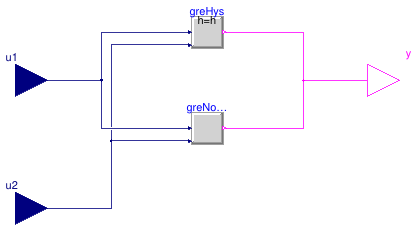
Block that outputs true if the Real input u1
is greater than the Real input u2, optionally within a hysteresis h.
The parameter h ≥ 0 is used to specify a hysteresis.
For any h ≥ 0, the output switches to true if u1 > u2,
and it switches to false if u1 ≤ u2 - h.
Note that in the special case of h = 0, this produces the output y=u1 > u2.
To disable hysteresis, set h=0.
Usage
Enabling hysteresis can avoid frequent switching.
In simulation, adding hysteresis is recommended to guard against numerical noise.
Otherwise, numerical noise from a nonlinear solver or from an
implicit time integration algorithm may cause the simulation to stall.
Numerical noise can be present if an input depends
on a state variable or a quantity that requires an iterative solution,
such as a temperature or a mass flow rate of an HVAC system.
In real controllers, adding hysteresis is recommended to guard against measurement noise.
Otherwise, measurement noise may cause the output to change frequently.
Parameters
| Type | Name | Default | Description |
|---|---|---|---|
| Real | h | 0 | Hysteresis |
| Advanced | |||
| Boolean | pre_y_start | false | Value of pre(y) at initial time |
Connectors
| Type | Name | Description |
|---|---|---|
| input RealInput | u1 | First input u1 |
| input RealInput | u2 | Second input u2 |
| output BooleanOutput | y | Output true if u1 is greater than u2 with hysteresis |
Modelica definition
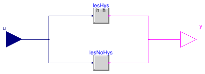
 Buildings.Controls.OBC.CDL.Reals.GreaterThreshold
Output y is true, if input u is greater than threshold with hysteresis
Information
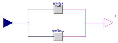
Block that outputs true if the Real input u
is greater than a threshold t, optionally within a hysteresis h.
The parameter h ≥ 0 is used to specify a hysteresis.
For any h ≥ 0, the output switches to true if u > t,
where t is the threshold,
and it switches to false if u ≤ t - h.
Note that in the special case of h = 0, this produces the output y=u > t.
To disable hysteresis, set h=0.
Usage
Enabling hysteresis can avoid frequent switching.
In simulation, adding hysteresis is recommended to guard against numerical noise.
Otherwise, numerical noise from a nonlinear solver or from an
implicit time integration algorithm may cause the simulation to stall.
Numerical noise can be present if an input depends
on a state variable or a quantity that requires an iterative solution,
such as a temperature or a mass flow rate of an HVAC system.
In real controllers, adding hysteresis is recommended to guard against measurement noise.
Otherwise, measurement noise may cause the output to change frequently.
Parameters
| Type | Name | Default | Description |
|---|---|---|---|
| Real | t | 0 | Threshold for comparison |
| Real | h | 0 | Hysteresis |
| Advanced | |||
| Boolean | pre_y_start | false | Value of pre(y) at initial time |
Connectors
| Type | Name | Description |
|---|---|---|
| input RealInput | u | Input to be compared against the threshold |
| output BooleanOutput | y | Outputs true if u is greater than the threshold with hysteresis |
Modelica definition
 Buildings.Controls.OBC.CDL.Reals.Hysteresis
Transform Real to Boolean signal with Hysteresis

Information
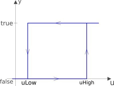
Block that transforms a Real input signal into a Boolean
output signal:
- When the output was
falseand the input becomes greater than the parameteruHigh, the output switches totrue. - When the output was
trueand the input becomes less than the parameteruLow, the output switches tofalse.
The start value of the output is defined via parameter
pre_y_start (= value of pre(y) at initial time).
The default value of this parameter is false.
Parameters
| Type | Name | Default | Description |
|---|---|---|---|
| Real | uLow | if y=true and u<uLow, switch to y=false | |
| Real | uHigh | if y=false and u>uHigh, switch to y=true | |
| Boolean | pre_y_start | false | Value of pre(y) at initial time |
Connectors
| Type | Name | Description |
|---|---|---|
| input RealInput | u | Input to be compared against hysteresis values |
| output BooleanOutput | y | Output value of comparison |
Modelica definition
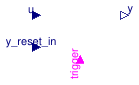
 Buildings.Controls.OBC.CDL.Reals.IntegratorWithReset
Output the integral of the input signal
Information
Block that outputs
y(t) = ystart + ∫t0t u(s) ds.
Whenever the input signal trigger changes from false
to true,
the integrator is reset by setting ystart
to the value of the input signal y_reset_in.
Parameters
| Type | Name | Default | Description |
|---|---|---|---|
| Real | k | 1 | Integrator gain |
| Initialization | |||
| Real | y_start | 0 | Initial or guess value of output (= state) |
Connectors
| Type | Name | Description |
|---|---|---|
| input RealInput | u | Input to be integrated |
| input RealInput | y_reset_in | Input signal for state to which integrator is reset |
| input BooleanInput | trigger | Input that resets the integrator output when it becomes true |
| output RealOutput | y | Value of the integrator |
Modelica definition
 Buildings.Controls.OBC.CDL.Reals.Less
Output y is true, if input u1 is less than input u2
Information
Block that outputs true if the Real input u1
is less than the Real input u2, optionally within a hysteresis h.
The parameter h ≥ 0 is used to specify a hysteresis.
For any h ≥ 0, the output switches to true if u1 < u2,
and it switches to false if u1 ≥ u2 + h.
Note that in the special case of h = 0, this produces the output y=u1 < u2.
To disable hysteresis, set h=0.
Usage
Enabling hysteresis can avoid frequent switching.
In simulation, adding hysteresis is recommended to guard against numerical noise.
Otherwise, numerical noise from a nonlinear solver or from an
implicit time integration algorithm may cause the simulation to stall.
Numerical noise can be present if an input depends
on a state variable or a quantity that requires an iterative solution,
such as a temperature or a mass flow rate of an HVAC system.
In real controllers, adding hysteresis is recommended to guard against measurement noise.
Otherwise, measurement noise may cause the output to change frequently.
Parameters
| Type | Name | Default | Description |
|---|---|---|---|
| Real | h | 0 | Hysteresis |
| Advanced | |||
| Boolean | pre_y_start | false | Value of pre(y) at initial time |
Connectors
| Type | Name | Description |
|---|---|---|
| input RealInput | u1 | First input u1 |
| input RealInput | u2 | Second input u2 |
| output BooleanOutput | y | Outputs true if u1 is less than u2 |
Modelica definition
 Buildings.Controls.OBC.CDL.Reals.LessThreshold
Output y is true, if input u is less than threshold with hysteresis
Information
Block that outputs true if the Real input u
is less than a threshold t, optionally within a hysteresis h.
The parameter h ≥ 0 is used to specify a hysteresis.
For any h ≥ 0, the output switches to true if u < t,
where t is the threshold,
and it switches to false if u ≥ t + h.
Note that in the special case of h = 0, this produces the output y=u < t.
Usage
Enabling hysteresis can avoid frequent switching. Adding hysteresis is recommended in real controllers to guard against sensor noise, and in simulation to guard against numerical noise. Numerical noise can be present if an input depends on a state variable or a quantity that requires an iterative solution, such as a temperature or a mass flow rate of an HVAC system. To disable hysteresis, set h=0.
Parameters
| Type | Name | Default | Description |
|---|---|---|---|
| Real | t | 0 | Threshold for comparison |
| Real | h | 0 | Hysteresis |
| Advanced | |||
| Boolean | pre_y_start | false | Value of pre(y) at initial time |
Connectors
| Type | Name | Description |
|---|---|---|
| input RealInput | u | Input to be compared against the threshold |
| output BooleanOutput | y | Outputs true if u is less than the threshold with hysteresis |
Modelica definition
 Buildings.Controls.OBC.CDL.Reals.LimitSlewRate
Limit the increase or decrease rate of input
Information
The block limits the rate of change of the input by a ramp.
This block computes a threshold for the rate of change of the output y as
thr = (u-y)/Td, where Td > 0 is parameter.
The output y is computed as follows:
-
If
thr < fallingSlewRate, thendy/dt = fallingSlewRate, -
if
thr > raisingSlewRate, thendy/dt = raisingSlewRate, -
otherwise,
dy/dt = thr.
Implementation
For the block to work with arbitrary inputs and in order to produce a differentiable output,
the input is numerically differentiated with derivative time constant Td.
Smaller time constant Td means nearer ideal derivative.
Parameters
| Type | Name | Default | Description |
|---|---|---|---|
| Real | raisingSlewRate | Speed with which to increase the output [1/s] | |
| Real | fallingSlewRate | -raisingSlewRate | Speed with which to decrease the output [1/s] |
| Real | Td | raisingSlewRate*10 | Derivative time constant [s] |
| Boolean | enable | true | Set to false to disable rate limiter |
Connectors
| Type | Name | Description |
|---|---|---|
| input RealInput | u | Input signal to be rate of change limited |
| output RealOutput | y | Rate of change limited output signal |
Modelica definition
 Buildings.Controls.OBC.CDL.Reals.Limiter
Limit the range of a signal
Information
Block that outputs y = min(uMax, max(uMin, u)),
where
u is an input
and
uMax and uMin are parameters.
If uMax < uMin, an error occurs.
Parameters
| Type | Name | Default | Description |
|---|---|---|---|
| Real | uMax | Upper limit of input signal | |
| Real | uMin | Lower limit of input signal |
Connectors
| Type | Name | Description |
|---|---|---|
| input RealInput | u | Input to be limited |
| output RealOutput | y | Limited value of input signal |
Modelica definition
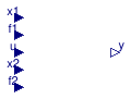
 Buildings.Controls.OBC.CDL.Reals.Line
Output the value of the input x along a line specified by two points
Information
Block that outputs y = a + b u,
where
u is an input
and the coefficients a and b
are determined so that the line intercepts the two input points
specified by the two points x1 and f1,
and x2 and f2.
The parameters limitBelow and limitAbove
determine whether x1 and x2 are also used
to limit the input u.
If the limits are used, then this block requires x1 < x2.
Parameters
| Type | Name | Default | Description |
|---|---|---|---|
| Boolean | limitBelow | true | If true, limit input u to be no smaller than x1 |
| Boolean | limitAbove | true | If true, limit input u to be no larger than x2 |
Connectors
| Type | Name | Description |
|---|---|---|
| input RealInput | x1 | Input for support point x1, with x1 < x2 |
| input RealInput | f1 | Input for support point f(x1) |
| input RealInput | x2 | Input for support point x2, with x2 > x1 |
| input RealInput | f2 | Input for support point f(x2) |
| input RealInput | u | Input for independent variable |
| output RealOutput | y | Output with f(x) along the line specified by (x1, f1) and (x2, f2) |
Modelica definition
 Buildings.Controls.OBC.CDL.Reals.Log
Output the natural (base e) logarithm of the input (input > 0 required)
Information
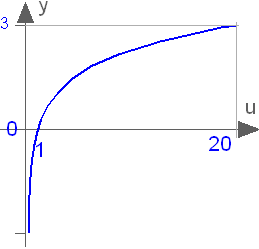
Block that outputs y = log(u),
where
u is an input and log() is the
natural logarithm (base-e) function.
An error occurs if the input u is
zero or negative.
Connectors
| Type | Name | Description |
|---|---|---|
| input RealInput | u | Input for base e logarithm |
| output RealOutput | y | Base e logarithm of the input |
Modelica definition
Buildings.Controls.OBC.CDL.Reals.Log10
Output the base 10 logarithm of the input (input > 0 required)
Information
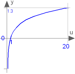
Block that outputs y = log10(u),
where
u is an input and log10() is the
logarithm (base-10) function.
An error occurs if the input u is
zero or negative.
Connectors
| Type | Name | Description |
|---|---|---|
| input RealInput | u | Input for base 10 logarithm |
| output RealOutput | y | Base 10 logarithm of the input |
Modelica definition
 Buildings.Controls.OBC.CDL.Reals.MatrixGain
Output the product of a gain matrix with the input signal vector
Information
This blocks computes output vector y as the product of the gain matrix K with the input signal vector u as y = K u. For example,
parameter Real K[:,:] = [0.12, 2; 3, 1.5];
results in
     | y[1] |     | 0.12,  2.00 |   | u[1] |
     |      |  =  |            | * |      |
     | y[2] |     | 3.00,  1.50 |   | u[2] |
Parameters
| Type | Name | Default | Description |
|---|---|---|---|
| Real | K[:, :] | [1, 0; 0, 1] | Gain matrix which is multiplied with the input |
Connectors
| Type | Name | Description |
|---|---|---|
| input RealInput | u[nin] | Input to be multiplied with the gain matrix |
| output RealOutput | y[nout] | Product of gain matrix times the input |
Modelica definition
 Buildings.Controls.OBC.CDL.Reals.MatrixMax
Output vector of row- or column-wise maximum of the input matrix
Information
If rowMax = true, this block outputs the row-wise maximum
of the input matrix u,
otherwise it outputs the column-wise maximum of the input matrix u.
Parameters
| Type | Name | Default | Description |
|---|---|---|---|
| Boolean | rowMax | true | If true, outputs row-wise maximum, otherwise column-wise |
| Integer | nRow | Number of rows in input matrix | |
| Integer | nCol | Number of columns in input matrix |
Connectors
| Type | Name | Description |
|---|---|---|
| input RealInput | u[nRow, nCol] | Input for the matrix max function |
| output RealOutput | y[if rowMax then size(u, 1) else size(u, 2)] | Output with vector of row- or colum-wise maximum of the input matrix |
Modelica definition
Buildings.Controls.OBC.CDL.Reals.MatrixMin
Output vector of row- or column-wise minimum values
Information
If rowMin = true, this block outputs the row-wise minimum
of the input matrix u,
otherwise it outputs the column-wise minimum of the input matrix u.
Parameters
| Type | Name | Default | Description |
|---|---|---|---|
| Boolean | rowMin | true | If true, outputs row-wise minimum, otherwise column-wise |
| Integer | nRow | Number of rows in input matrix | |
| Integer | nCol | Number of columns in input matrix |
Connectors
| Type | Name | Description |
|---|---|---|
| input RealInput | u[nRow, nCol] | Input for the matrix min function |
| output RealOutput | y[if rowMin then size(u, 1) else size(u, 2)] | Output with vector of row- or colum-wise minimum of the input matrix |
Modelica definition
Buildings.Controls.OBC.CDL.Reals.Max
Pass through the largest signal
Information
Block that outputs y = max(u1, u2),
where
u1 and u2 are inputs.
Connectors
| Type | Name | Description |
|---|---|---|
| input RealInput | u1 | Input to the max function |
| input RealInput | u2 | Input to the max function |
| output RealOutput | y | Maximum of the inputs |
Modelica definition
Buildings.Controls.OBC.CDL.Reals.Min
Pass through the smallest signal
Information
Block that outputs y = min(u1, u2),
where
u1 and u2 are inputs.
Connectors
| Type | Name | Description |
|---|---|---|
| input RealInput | u1 | Input to the min function |
| input RealInput | u2 | Input to the min function |
| output RealOutput | y | Minimum of the inputs |
Modelica definition
 Buildings.Controls.OBC.CDL.Reals.Modulo
Output the remainder of first input divided by second input (~=0)
Information
Block that outputs y = mod(u1/u2),
where
u1 and u2 are inputs.
Connectors
| Type | Name | Description |
|---|---|---|
| input RealInput | u1 | Dividend of the modulus function |
| input RealInput | u2 | Divisor of the modulus function |
| output RealOutput | y | Modulus u1 mod u2 |
Modelica definition
 Buildings.Controls.OBC.CDL.Reals.MovingAverage
Block to output moving average
Information
This block outputs the mean value of its input signal as
      1  t
y =   -  ∫   u(s) ds
      δ  t-δ
where δ is a parameter that determines the time window over which the input is averaged. For t < δ seconds, it outputs
           1      t
y =   --------    ∫   u(s) ds
      t-t0+10-10   t0
where t0 is the initial time.
This block can for example be used to output the moving average of a noisy measurement signal.
See Buildings.Controls.OBC.CDL.Reals.Validation.MovingAverage and Buildings.Controls.OBC.CDL.Reals.Validation.MovingAverage_nonZeroStart for example.
Parameters
| Type | Name | Default | Description |
|---|---|---|---|
| Real | delta | Time horizon over which the input is averaged [s] |
Connectors
| Type | Name | Description |
|---|---|---|
| input RealInput | u | Input to be averaged |
| output RealOutput | y | Moving average of the input |
Modelica definition
Buildings.Controls.OBC.CDL.Reals.MultiMax
Output the maximum element of the input vector

Information
Outputs the maximum element of the input vector.
Connectors
| Type | Name | Description |
|---|---|---|
| input RealInput | u[nin] | Input to max function |
| output RealOutput | y | Largest element of the input vector |
Modelica definition
Buildings.Controls.OBC.CDL.Reals.MultiMin
Output the minimum element of the input vector
Information
Outputs the minimum element of the input vector.
Connectors
| Type | Name | Description |
|---|---|---|
| input RealInput | u[nin] | Input to the min function |
| output RealOutput | y | Smallest element of the input vector |
Modelica definition
 Buildings.Controls.OBC.CDL.Reals.MultiSum
Sum of Reals, y = k[1]*u[1] + k[2]*u[2] + ... + k[n]*u[n]
Information
Block that outputs
y = ∑i=1n ki ui,
where k is a parameter with n elements and u is an input of the same length. The dimension of u can be enlarged by drawing an additional connection line. The connection is automatically connected to this new free index.
If no connection to the input connector u is present, the output is y=0.
See Buildings.Controls.OBC.CDL.Reals.Validation.MultiSum for an example.
Parameters
| Type | Name | Default | Description |
|---|---|---|---|
| Real | k[nin] | fill(1, nin) | Input gains |
Connectors
| Type | Name | Description |
|---|---|---|
| input RealInput | u[nin] | Input to multiplied by gain and then added |
| output RealOutput | y | Sum of inputs times gains |
Modelica definition
 Buildings.Controls.OBC.CDL.Reals.Multiply
Output product of the two inputs
Information
Block that outputs y = u1 * u2,
where
u1 and u2 are inputs.
Connectors
| Type | Name | Description |
|---|---|---|
| input RealInput | u1 | Input to be multiplied |
| input RealInput | u2 | Input to be multiplied |
| output RealOutput | y | Product of the inputs |
Modelica definition
 Buildings.Controls.OBC.CDL.Reals.MultiplyByParameter
Output the product of a gain value with the input signal
Information
Block that outputs y = k * u,
where
k is a parameter and
u is an input.
Parameters
| Type | Name | Default | Description |
|---|---|---|---|
| Real | k | Factor to be multiplied with input signal |
Connectors
| Type | Name | Description |
|---|---|---|
| input RealInput | u | Input to be multiplied with gain |
| output RealOutput | y | Product of the parameter times the input |
Modelica definition
 Buildings.Controls.OBC.CDL.Reals.PID
P, PI, PD, and PID controller
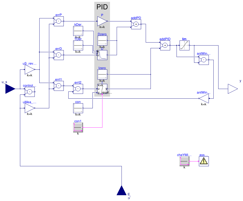
Information
PID controller in the standard form
yu = k/r (e(t) + 1 ⁄ Ti ∫ e(τ) dτ + Td d⁄dt e(t)),
where yu is the control signal before output limitation, e(t) = us(t) - um(t) is the control error, with us being the set point and um being the measured quantity, k is the gain, Ti is the time constant of the integral term, Td is the time constant of the derivative term, and r is a scaling factor, with default r=1. The scaling factor should be set to the typical order of magnitude of the range of the error e. For example, you may set r=100 to r=1000 if the control input is a pressure of a heating water circulation pump in units of Pascal, or leave r=1 if the control input is a room temperature.
Note that the units of k are the inverse of the units of the control error, while the units of Ti and Td are seconds.
The actual control output is
y = min( ymax, max( ymin, y)),
where ymin and ymax are limits for the control signal.
P, PI, PD, or PID action
Through the parameter controllerType, the controller can be configured
as P, PI, PD or PID controller. The default configuration is PI.
Reverse or direct action
Through the parameter reverseActing, the controller can be configured to
be reverse or direct acting.
The above standard form is reverse acting, which is the default configuration.
For a reverse acting controller, for a constant set point,
an increase in measurement signal u_m decreases the control output signal y
(Montgomery and McDowall, 2008).
Thus,
-
for a heating coil with a two-way valve, leave
reverseActing = true, but -
for a cooling coil with a two-way valve, set
reverseActing = false.
If reverseAction=false, then the error e above is multiplied by -1.
Anti-windup compensation
The controller anti-windup compensation is as follows: Instead of the above basic control law, the implementation is
yu = k (e(t) ⁄ r + 1 ⁄ Ti ∫ (-Δy + e(τ) ⁄ r) dτ + Td ⁄ r d⁄dt e(t)),
where the anti-windup compensation Δy is
Δy = (yu - y) ⁄ (k Ni),
where Ni > 0 is the time constant for the anti-windup compensation. To accelerate the anti-windup, decrease Ni.
Note that the anti-windup term (-Δy + e(τ) ⁄ r) shows that the range of the typical control error r should be set to a reasonable value so that
e(τ) ⁄ r = (us(τ) - um(τ)) ⁄ r
has order of magnitude one, and hence the anti-windup compensation should work well.
Reset of the controller output
Note that this controller implements an integrator anti-windup. Therefore, for most applications, the controller output does not need to be reset. However, if the controller is used in conjuction with equipment that is being switched on, better control performance may be achieved by resetting the controller output when the equipment is switched on. This is in particular the case in situations where the equipment control input should continuously increase as the equipment is switched on, such as a light dimmer that may slowly increase the luminance, or a variable speed drive of a motor that should continuously increase the speed. In this case, the controller Buildings.Controls.OBC.CDL.Reals.PIDWithReset that can reset the output should be used.
Approximation of the derivative term
The derivative of the control error d ⁄ dt e(t) is approximated using
d⁄dt x(t) = (e(t)-x(t)) Nd ⁄ Td,
and
d⁄dt e(t) ≈ Nd (e(t)-x(t)),
where x(t) is an internal state.
Guidance for tuning the control gains
The parameters of the controller can be manually adjusted by performing closed loop tests (= controller + plant connected together) and using the following strategy:
- Set very large limits, e.g., set ymax = 1000.
-
Select a P-controller and manually enlarge the parameter
k(the total gain of the controller) until the closed-loop response cannot be improved any more. -
Select a PI-controller and manually adjust the parameters
kandTi(the time constant of the integrator). The first value ofTican be selected such that it is in the order of the time constant of the oscillations occurring with the P-controller. If, e.g., oscillations in the order of 100 seconds occur in the previous step, start withTi=1/100seconds. -
If you want to make the reaction of the control loop faster
(but probably less robust against disturbances and measurement noise)
select a PID-controller and manually adjust parameters
k,Ti,Td(time constant of derivative block). -
Set the limits
yMaxandyMinaccording to your specification. -
Perform simulations such that the output of the PID controller
goes in its limits. Tune
Ni(Ni Ti is the time constant of the anti-windup compensation) such that the input to the limiter block (=lim.u) goes quickly enough back to its limits. IfNiis decreased, this happens faster. IfNiis very large, the anti-windup compensation is not effective and the controller works bad.
References
R. Montgomery and R. McDowall (2008). "Fundamentals of HVAC Control Systems." American Society of Heating Refrigerating and Air-Conditioning Engineers Inc. Atlanta, GA.
Parameters
| Type | Name | Default | Description |
|---|---|---|---|
| SimpleController | controllerType | Buildings.Controls.OBC.CDL.T... | Type of controller |
| Real | r | 1 | Typical range of control error, used for scaling the control error |
| Boolean | reverseActing | true | Set to true for reverse acting, or false for direct acting control action |
| Control gains | |||
| Real | k | 1 | Gain of controller |
| Real | Ti | 0.5 | Time constant of integrator block [s] |
| Real | Td | 0.1 | Time constant of derivative block [s] |
| Limits | |||
| Real | yMax | 1 | Upper limit of output |
| Real | yMin | 0 | Lower limit of output |
| Advanced | |||
| Integrator anti-windup | |||
| Real | Ni | 0.9 | Ni*Ti is time constant of anti-windup compensation |
| Derivative block | |||
| Real | Nd | 10 | The higher Nd, the more ideal the derivative block |
| Initialization | |||
| Real | xi_start | 0 | Initial value of integrator state |
| Real | yd_start | 0 | Initial value of derivative output |
Connectors
| Type | Name | Description |
|---|---|---|
| input RealInput | u_s | Setpoint input signal |
| input RealInput | u_m | Measurement input signal |
| output RealOutput | y | Actuator output signal |
Modelica definition
 Buildings.Controls.OBC.CDL.Reals.PIDWithReset
P, PI, PD, and PID controller with output reset
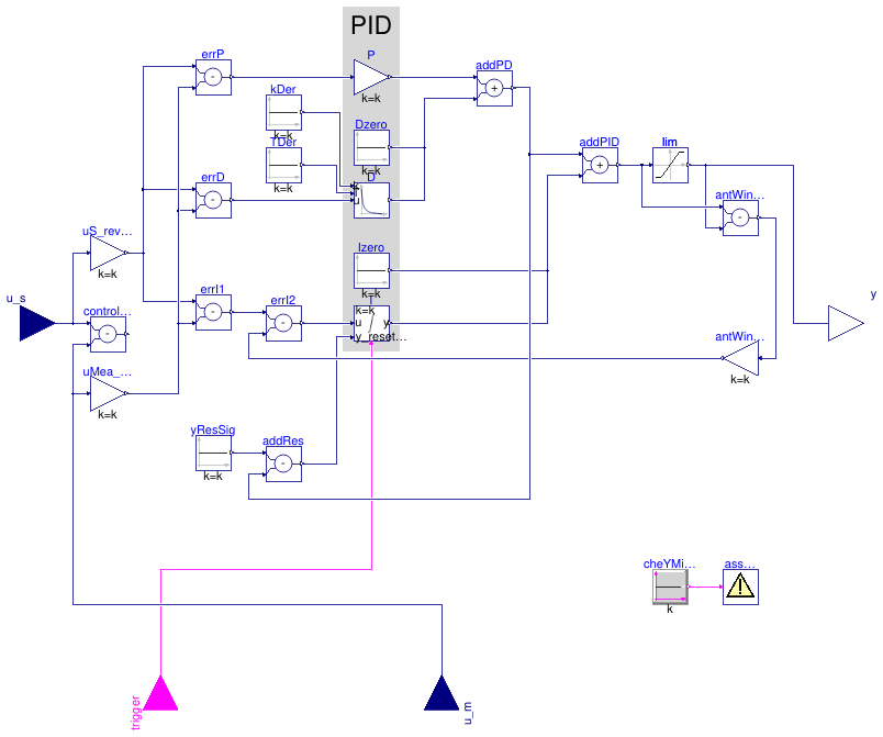
Information
PID controller in the standard form
yu = k/r (e(t) + 1 ⁄ Ti ∫ e(τ) dτ + Td d⁄dt e(t)),
with output reset, where yu is the control signal before output limitation, e(t) = us(t) - um(t) is the control error, with us being the set point and um being the measured quantity, k is the gain, Ti is the time constant of the integral term, Td is the time constant of the derivative term, and r is a scaling factor, with default r=1. The scaling factor should be set to the typical order of magnitude of the range of the error e. For example, you may set r=100 to r=1000 if the control input is a pressure of a heating water circulation pump in units of Pascal, or leave r=1 if the control input is a room temperature.
Note that the units of k are the inverse of the units of the control error, while the units of Ti and Td are seconds.
The actual control output is
y = min( ymax, max( ymin, y)),
where ymin and ymax are limits for the control signal.
P, PI, PD, or PID action
Through the parameter controllerType, the controller can be configured
as P, PI, PD or PID controller. The default configuration is PI.
Reverse or direct action
Through the parameter reverseActing, the controller can be configured to
be reverse or direct acting.
The above standard form is reverse acting, which is the default configuration.
For a reverse acting controller, for a constant set point,
an increase in measurement signal u_m decreases the control output signal y
(Montgomery and McDowall, 2008).
Thus,
-
for a heating coil with a two-way valve, leave
reverseActing = true, but -
for a cooling coil with a two-way valve, set
reverseActing = false.
If reverseAction=false, then the error e above is multiplied by -1.
Anti-windup compensation
The controller anti-windup compensation is as follows: Instead of the above basic control law, the implementation is
yu = k (e(t) ⁄ r + 1 ⁄ Ti ∫ (-Δy + e(τ) ⁄ r) dτ + Td ⁄ r d⁄dt e(t)),
where the anti-windup compensation Δy is
Δy = (yu - y) ⁄ (k Ni),
where Ni > 0 is the time constant for the anti-windup compensation. To accelerate the anti-windup, decrease Ni.
Note that the anti-windup term (-Δy + e(τ) ⁄ r) shows that the range of the typical control error r should be set to a reasonable value so that
e(τ) ⁄ r = (us(τ) - um(τ)) ⁄ r
has order of magnitude one, and hence the anti-windup compensation should work well.
Reset of the controller output
Whenever the value of boolean input signal trigger changes from
false to true, the controller output is reset by setting
y to the value of the parameter y_reset.
Approximation of the derivative term
The derivative of the control error d ⁄ dt e(t) is approximated using
d⁄dt x(t) = (e(t)-x(t)) Nd ⁄ Td,
and
d⁄dt e(t) ≈ Nd (e(t)-x(t)),
where x(t) is an internal state.
Guidance for tuning the control gains
The parameters of the controller can be manually adjusted by performing closed loop tests (= controller + plant connected together) and using the following strategy:
- Set very large limits, e.g., set ymax = 1000.
-
Select a P-controller and manually enlarge the parameter
k(the total gain of the controller) until the closed-loop response cannot be improved any more. -
Select a PI-controller and manually adjust the parameters
kandTi(the time constant of the integrator). The first value ofTican be selected such that it is in the order of the time constant of the oscillations occurring with the P-controller. If, e.g., oscillations in the order of 100 seconds occur in the previous step, start withTi=1/100seconds. -
If you want to make the reaction of the control loop faster
(but probably less robust against disturbances and measurement noise)
select a PID-controller and manually adjust parameters
k,Ti,Td(time constant of derivative block). -
Set the limits
yMaxandyMinaccording to your specification. -
Perform simulations such that the output of the PID controller
goes in its limits. Tune
Ni(Ni Ti is the time constant of the anti-windup compensation) such that the input to the limiter block (=lim.u) goes quickly enough back to its limits. IfNiis decreased, this happens faster. IfNiis very large, the anti-windup compensation is not effective and the controller works bad.
References
R. Montgomery and R. McDowall (2008). "Fundamentals of HVAC Control Systems." American Society of Heating Refrigerating and Air-Conditioning Engineers Inc. Atlanta, GA.
Parameters
| Type | Name | Default | Description |
|---|---|---|---|
| SimpleController | controllerType | Buildings.Controls.OBC.CDL.T... | Type of controller |
| Real | r | 1 | Typical range of control error, used for scaling the control error |
| Boolean | reverseActing | true | Set to true for reverse acting, or false for direct acting control action |
| Control gains | |||
| Real | k | 1 | Gain of controller |
| Real | Ti | 0.5 | Time constant of integrator block [s] |
| Real | Td | 0.1 | Time constant of derivative block [s] |
| Limits | |||
| Real | yMax | 1 | Upper limit of output |
| Real | yMin | 0 | Lower limit of output |
| Integrator reset | |||
| Real | y_reset | xi_start | Value to which the controller output is reset if the boolean trigger has a rising edge |
| Advanced | |||
| Integrator anti-windup | |||
| Real | Ni | 0.9 | Ni*Ti is time constant of anti-windup compensation |
| Derivative block | |||
| Real | Nd | 10 | The higher Nd, the more ideal the derivative block |
| Initialization | |||
| Real | xi_start | 0 | Initial value of integrator state |
| Real | yd_start | 0 | Initial value of derivative output |
Connectors
| Type | Name | Description |
|---|---|---|
| input RealInput | u_s | Connector of setpoint input signal |
| input RealInput | u_m | Connector of measurement input signal |
| output RealOutput | y | Connector of actuator output signal |
| input BooleanInput | trigger | Resets the controller output when trigger becomes true |
Modelica definition
 Buildings.Controls.OBC.CDL.Reals.Ramp
Limit the changing rate of the input
Information
Block that limits the rate of change of the input u by a ramp
if the boolean input active is true,
otherwise the block outputs y = u.
This block computes a threshold for the rate of change between
input u and output y as
thr = (u-y)/Td, where Td > 0 is a parameter.
The output y is computed as follows:
-
If
thr < fallingSlewRate, thendy/dt = fallingSlewRate, -
if
thr > raisingSlewRate, thendy/dt = raisingSlewRate, -
otherwise,
dy/dt = thr.
A smaller time constant Td > 0 means a higher accuracy for the derivative approximation.
Note that when the input activate switches to false,
the output y can have a discontinuity.
Implementation
For the block to work with arbitrary inputs and in order to produce a differentiable output,
the input is numerically differentiated with derivative time constant Td.
Parameters
| Type | Name | Default | Description |
|---|---|---|---|
| Real | raisingSlewRate | Maximum speed with which to increase the output [1/s] | |
| Real | fallingSlewRate | -raisingSlewRate | Maximum speed with which to decrease the output [1/s] |
| Real | Td | raisingSlewRate*0.001 | Derivative time constant [s] |
Connectors
| Type | Name | Description |
|---|---|---|
| input RealInput | u | Input that is being rate limited |
| input BooleanInput | active | Set to true to enable rate limiter |
| output RealOutput | y | Rate limited output if active is true, else output is equal to input |
Modelica definition
Buildings.Controls.OBC.CDL.Reals.Round
Round real number to given digits
Information
Block that outputs the input after rounding it to n digits.
For example,
-
set
n = 0to round to the nearest integer, -
set
n = 1to round to the next decimal point, and -
set
n = -1to round to the next multiple of ten.
Hence, the block outputs
    y = floor(u*(10^n) + 0.5)/(10^n)  for  u > 0,
    y = ceil(u*(10^n) - 0.5)/(10^n)   for  u < 0.
Parameters
| Type | Name | Default | Description |
|---|---|---|---|
| Integer | n | Number of digits to be round to |
Connectors
| Type | Name | Description |
|---|---|---|
| input RealInput | u | Input to be rounded |
| output RealOutput | y | Output with rounded input |
Modelica definition
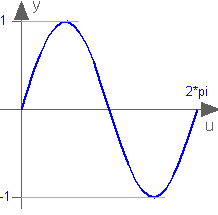
 Buildings.Controls.OBC.CDL.Reals.Sin
Output the sine of the input
Information
Block that outputs y = sin(u),
where
u is an input.
Connectors
| Type | Name | Description |
|---|---|---|
| input RealInput | u | Input for the sine function [rad] |
| output RealOutput | y | Sine of input |
Modelica definition
 Buildings.Controls.OBC.CDL.Reals.Sort
Sort elements of input vector in ascending or descending order
Information
Block that sorts the elements of the input signal u.
If the parameter ascending = true, then the output signal y satisfies
yi <= yi+1 for all i ∈ {1, ..., n-1}.
Otherwise, it satisfies
yi >= yi+1 for all i ∈ {1, ..., n-1}.
The output signal yIdx contains the indices of the sorted elements,
with respect to the input vector u.
Usage
Note that this block shall only be used for input signals u that are
time sampled.
Otherwise, in simulation, numerical noise from a nonlinear solver or from an
implicit time integration algorithm may cause the simulation to stall.
Numerical noise can be present if an input depends
on a state variable or a quantity that requires an iterative solution,
such as a temperature or a mass flow rate of an HVAC system.
In real controllers, measurement noise may cause the output to change frequently.
This block may for example be used in a variable air volume flow controller to access the position of the dampers that are most open.
Parameters
| Type | Name | Default | Description |
|---|---|---|---|
| Boolean | ascending | true | Set to true if ascending order, otherwise order is descending |
Connectors
| Type | Name | Description |
|---|---|---|
| input RealInput | u[nin] | Input to be sorted |
| output RealOutput | y[nin] | Output with sorted input |
| output IntegerOutput | yIdx[nin] | Indices of the sorted vector with respect to the original vector |
Modelica definition
 Buildings.Controls.OBC.CDL.Reals.Sqrt
Output the square root of the input (input >= 0 required)
Information
Block that outputs square root of the input y = sqrt(u),
where u is an input. The input u must be non-negative.
Connectors
| Type | Name | Description |
|---|---|---|
| input RealInput | u | Input to square root function |
| output RealOutput | y | Output with square root of the input |
Modelica definition
 Buildings.Controls.OBC.CDL.Reals.Subtract
Output the difference of the two inputs
Information
Block that outputs y as the difference of the
two input signals u1 and u2,
y = u1 - u2
Connectors
| Type | Name | Description |
|---|---|---|
| input RealInput | u1 | Input with minuend |
| input RealInput | u2 | Input with subtrahend |
| output RealOutput | y | Output with difference |
Modelica definition
 Buildings.Controls.OBC.CDL.Reals.Switch
Switch between two Real signals
Information
Block that outputs one of two real input signals based on a boolean input signal.
If the input signal u2 is true,
the block outputs y = u1.
Otherwise, it outputs y = u3.
Connectors
| Type | Name | Description |
|---|---|---|
| input RealInput | u1 | Input u1 |
| input BooleanInput | u2 | Boolean switch input signal, if true, y=u1, else y=u3 |
| input RealInput | u3 | Input u3 |
| output RealOutput | y | Output with u1 if u2 is true, else u3 |
Modelica definition
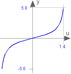
 Buildings.Controls.OBC.CDL.Reals.Tan
Output the tangent of the input
Information
Block that outputs y = tan(u),
where
u is an input.
Connectors
| Type | Name | Description |
|---|---|---|
| input RealInput | u | Input for the tangent function [rad] |
| output RealOutput | y | Tangent of the input |
Modelica definition
 Buildings.Controls.OBC.CDL.Reals.Greater.GreaterWithHysteresis
Greater block without hysteresis
Parameters
| Type | Name | Default | Description |
|---|---|---|---|
| Real | h | 0 | Hysteresis |
| Advanced | |||
| Boolean | pre_y_start | false | Value of pre(y) at initial time |
Connectors
| Type | Name | Description |
|---|---|---|
| input RealInput | u1 | Input u1 |
| input RealInput | u2 | Input u2 |
| output BooleanOutput | y | Output y |
Modelica definition
Buildings.Controls.OBC.CDL.Reals.Greater.GreaterNoHysteresis
Greater block without hysteresis
Connectors
| Type | Name | Description |
|---|---|---|
| input RealInput | u1 | Input u1 |
| input RealInput | u2 | Input u2 |
| output BooleanOutput | y | Output y |
Modelica definition
 Buildings.Controls.OBC.CDL.Reals.GreaterThreshold.GreaterWithHysteresis
Greater block without hysteresis
Parameters
| Type | Name | Default | Description |
|---|---|---|---|
| Real | t | 0 | Threshold for comparison |
| Real | h | 0 | Hysteresis |
| Advanced | |||
| Boolean | pre_y_start | false | Value of pre(y) at initial time |
Connectors
| Type | Name | Description |
|---|---|---|
| input RealInput | u | Input u |
| output BooleanOutput | y | Output y |
Modelica definition
Buildings.Controls.OBC.CDL.Reals.GreaterThreshold.GreaterNoHysteresis
Greater block without hysteresis
Parameters
| Type | Name | Default | Description |
|---|---|---|---|
| Real | t | 0 | Threshold for comparison |
Connectors
| Type | Name | Description |
|---|---|---|
| input RealInput | u | Input u |
| output BooleanOutput | y | Output y |
Modelica definition
Buildings.Controls.OBC.CDL.Reals.Less.LessWithHysteresis
Less block without hysteresis
Parameters
| Type | Name | Default | Description |
|---|---|---|---|
| Real | h | 0 | Hysteresis |
| Advanced | |||
| Boolean | pre_y_start | false | Value of pre(y) at initial time |
Connectors
| Type | Name | Description |
|---|---|---|
| input RealInput | u1 | Input u1 |
| input RealInput | u2 | Input u2 |
| output BooleanOutput | y | Output y |
Modelica definition
Buildings.Controls.OBC.CDL.Reals.Less.LessNoHysteresis
Less block without hysteresis
Connectors
| Type | Name | Description |
|---|---|---|
| input RealInput | u1 | Input u1 |
| input RealInput | u2 | Input u2 |
| output BooleanOutput | y | Output y |
Modelica definition
Buildings.Controls.OBC.CDL.Reals.LessThreshold.LessWithHysteresis
Less block without hysteresis
Parameters
| Type | Name | Default | Description |
|---|---|---|---|
| Real | t | 0 | Threshold for comparison |
| Real | h | 0 | Hysteresis |
| Advanced | |||
| Boolean | pre_y_start | false | Value of pre(y) at initial time |
Connectors
| Type | Name | Description |
|---|---|---|
| input RealInput | u | Input u |
| output BooleanOutput | y | Output y |
Modelica definition
Buildings.Controls.OBC.CDL.Reals.LessThreshold.LessNoHysteresis
Less block without hysteresis
Parameters
| Type | Name | Default | Description |
|---|---|---|---|
| Real | t | 0 | Threshold for comparison |
Connectors
| Type | Name | Description |
|---|---|---|
| input RealInput | u | Input u |
| output BooleanOutput | y | Output y |