Buildings.Examples.VAVReheat.BaseClasses.Controls
Package with controller models
Information
Extends from Modelica.Icons.VariantsPackage (Icon for package containing variants).
Package Content
| Name | Description |
|---|---|
| Empty control bus that is adapted to the signals connected to it | |
| Computes the duct static pressure setpoint | |
| Controller for economizer | |
| Controller for fan revolution | |
| Freeze thermostat with timed lockout | |
| Finite State Machine for the operational modes | |
| Enumeration for modes of operation | |
| Outputs true when precooling should start | |
| Set point scheduler for room temperature | |
| Controller for room VAV box | |
| Block that outputs the mode if the state is active, or zero otherwise | |
| Control block for tracking the supply air temperature set point | |
| Block computing the supply air temperature set point based on the operation mode | |
| Block that applies hysteresis and a minimum on timer to a control signal | |
| Example models to test the components |
Types and constants
  type OperationModes = enumeration(
      occupied "Occupied",
      unoccupiedOff "Unoccupied off",
      unoccupiedNightSetBack "Unoccupied, night set back",
      unoccupiedWarmUp "Unoccupied, warm-up",
      unoccupiedPreCool "Unoccupied, pre-cool",
      safety "Safety (smoke, fire, etc.)") "Enumeration for modes of operation";
 Buildings.Examples.VAVReheat.BaseClasses.Controls.ControlBus
Empty control bus that is adapted to the signals connected to it

Information
This connector defines the expandable connector ControlBus that
is used to connect control signals.
Note, this connector is empty. When using it, the actual content is
constructed by the signals connected to this bus.
Extends from Modelica.Icons.SignalBus (Icon for signal bus).
Modelica definition
 Buildings.Examples.VAVReheat.BaseClasses.Controls.DuctStaticPressureSetpoint
Computes the duct static pressure setpoint
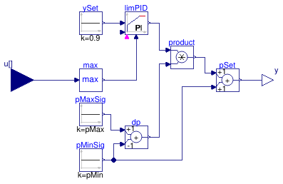
Information
Extends from Modelica.Blocks.Interfaces.MISO (Multiple Input Single Output continuous control block).
Parameters
| Type | Name | Default | Description |
|---|---|---|---|
| Integer | nin | 1 | Number of inputs |
| AbsolutePressure | pMin | 100 | Minimum duct static pressure setpoint [Pa] |
| AbsolutePressure | pMax | 410 | Maximum duct static pressure setpoint [Pa] |
| Real | k | 0.1 | Gain of controller |
| Time | Ti | 60 | Time constant of integrator block [s] |
| Time | Td | 60 | Time constant of derivative block [s] |
| SimpleController | controllerType | Modelica.Blocks.Types.Simple... | Type of controller |
Connectors
| Type | Name | Description |
|---|---|---|
| input RealInput | u[nin] | Connector of Real input signals |
| output RealOutput | y | Connector of Real output signal |
Modelica definition
 Buildings.Examples.VAVReheat.BaseClasses.Controls.Economizer
Controller for economizer
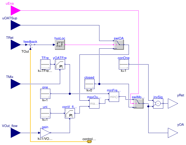
Information
This is a controller for an economizer, that adjusts the mixed air dampers to fulfill three control functions.
- Freeze protection, based on the mixed air temperature measurement
- Minimum outside air requirement, based on the outdoor air flow rate measurement
- Supply air cooling, based on the logic implemented in Buildings.Examples.VAVReheat.BaseClasses.Controls.SupplyAirTemperature, with the additional condition that when the outside air dry bulb is greater than the return air dry bulb, economizer cooling is disabled.
Parameters
| Type | Name | Default | Description |
|---|---|---|---|
| Boolean | have_reset | false | Set to true to reset the outdoor air damper controllers with the enable signal |
| Boolean | have_frePro | false | Set to true to enable freeze protection (mixed air low temperature control) |
| Temperature | TFreSet | 277.15 | Lower limit of mixed air temperature for freeze protection [K] |
| TemperatureDifference | dTLock | 1 | Temperature difference between return and outdoor air for economizer lockout [K] |
| VolumeFlowRate | VOut_flow_min | Minimum outside air volume flow rate [m3/s] | |
| SimpleController | controllerType | Modelica.Blocks.Types.Simple... | Type of controller |
| Real | k | 0.05 | Gain of controller |
| Time | Ti | 120 | Time constant of integrator block [s] |
Connectors
| Type | Name | Description |
|---|---|---|
| input BooleanInput | uEna | Enable signal for economizer |
| ControlBus | controlBus | Control bus |
| input RealInput | uOATSup | Control signal for outdoor air damper from supply temperature controller |
| input RealInput | TMix | Measured mixed air temperature |
| input RealInput | VOut_flow | Measured outside air flow rate |
| input RealInput | TRet | Return air temperature |
| output RealOutput | yRet | Control signal for return air damper |
| output RealOutput | yOA | Control signal for outside air damper |
Modelica definition
 Buildings.Examples.VAVReheat.BaseClasses.Controls.FanVFD
Controller for fan revolution
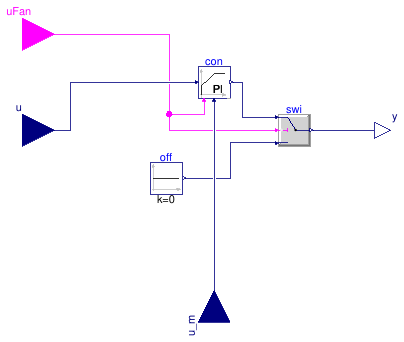
Information
PI controller for the fan speed. The controller outputs y = 0 if the fan control signal is off, e.g., if uFan = false.
Extends from Modelica.Blocks.Interfaces.SISO (Single Input Single Output continuous control block).
Parameters
| Type | Name | Default | Description |
|---|---|---|---|
| Real | xSet_nominal | Nominal setpoint (used for normalization) | |
| Real | r_N_min | 0.01 | Minimum normalized fan speed |
| Init | initType | Modelica.Blocks.Types.Init.N... | Type of initialization (1: no init, 2: steady state, 3/4: initial output) |
| Real | y_start | 0 | Initial or guess value of output (= state) |
| Setpoint tracking | |||
| SimpleController | controllerType | Modelica.Blocks.Types.Simple... | Type of controller |
| Real | k | 0.5 | Gain of controller |
| Time | Ti | 15 | Time constant of integrator block [s] |
Connectors
| Type | Name | Description |
|---|---|---|
| input RealInput | u | Connector of Real input signal |
| output RealOutput | y | Connector of Real output signal |
| input RealInput | u_m | Connector of measurement input signal |
| input BooleanInput | uFan | Set to true to enable the fan on |
Modelica definition
 Buildings.Examples.VAVReheat.BaseClasses.Controls.FreezeStat
Freeze thermostat with timed lockout
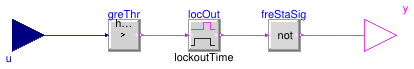
Information
Freeze stat that outputs true if freeze protection should be engaged.
The freeze stat regulates around a set point. When it triggers freeze protection,
then the freeze protection stays engaged for at least delayTime.
It only becomes disengaged after this time period if the measured temperature is above
the set point.
Parameters
| Type | Name | Default | Description |
|---|---|---|---|
| Real | lockoutTime | 900 | Delay time [s] |
| Real | TSet | 276.15 | Temperature below which the freeze protection starts [K] |
Connectors
| Type | Name | Description |
|---|---|---|
| input RealInput | u | Connector of Real input signal used as measurement signal [K] |
| output BooleanOutput | y | Connector of Real output signal used as actuator signal |
Modelica definition
 Buildings.Examples.VAVReheat.BaseClasses.Controls.ModeSelector
Finite State Machine for the operational modes
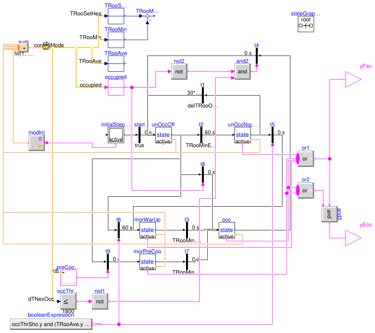
Parameters
| Type | Name | Default | Description |
|---|---|---|---|
| TemperatureDifference | delTRooOnOff | 1 | Deadband in room temperature between occupied on and occupied off [K] |
| Temperature | TRooSetHeaOcc | 293.15 | Set point for room air temperature during heating mode [K] |
| Temperature | TRooSetCooOcc | 299.15 | Set point for room air temperature during cooling mode [K] |
Connectors
| Type | Name | Description |
|---|---|---|
| ControlBus | cb | |
| output BooleanOutput | yFan | True if the fans are to be switched on |
| output BooleanOutput | yEco | True if the economizer is enabled |
Modelica definition
Buildings.Examples.VAVReheat.BaseClasses.Controls.OperationModes
Enumeration for modes of operation
Modelica definition
 Buildings.Examples.VAVReheat.BaseClasses.Controls.PreCoolingStarter
Outputs true when precooling should start
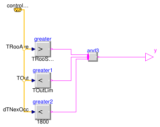
Information
Extends from Modelica.Blocks.Interfaces.BooleanSignalSource (Base class for Boolean signal sources).
Parameters
| Type | Name | Default | Description |
|---|---|---|---|
| Temperature | TOutLim | 286.15 | Limit for activating precooling [K] |
| Temperature | TRooSetCooOcc | Set point for room air temperature during cooling mode [K] |
Connectors
| Type | Name | Description |
|---|---|---|
| output BooleanOutput | y | Connector of Boolean output signal |
| ControlBus | controlBus |
Modelica definition
 Buildings.Examples.VAVReheat.BaseClasses.Controls.RoomTemperatureSetpoint
Set point scheduler for room temperature
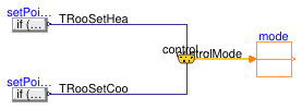
Information
Extends from Modelica.Blocks.Icons.Block (Basic graphical layout of input/output block).
Parameters
| Type | Name | Default | Description |
|---|---|---|---|
| Temperature | THeaOn | 293.15 | Heating setpoint during on [K] |
| Temperature | THeaOff | 285.15 | Heating setpoint during off [K] |
| Temperature | TCooOn | 297.15 | Cooling setpoint during on [K] |
| Temperature | TCooOff | 303.15 | Cooling setpoint during off [K] |
Connectors
| Type | Name | Description |
|---|---|---|
| ControlBus | controlBus |
Modelica definition
 Buildings.Examples.VAVReheat.BaseClasses.Controls.RoomVAV
Controller for room VAV box
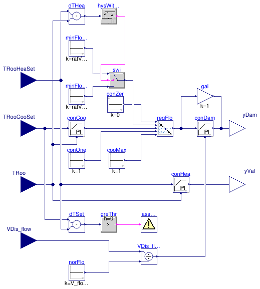
Information
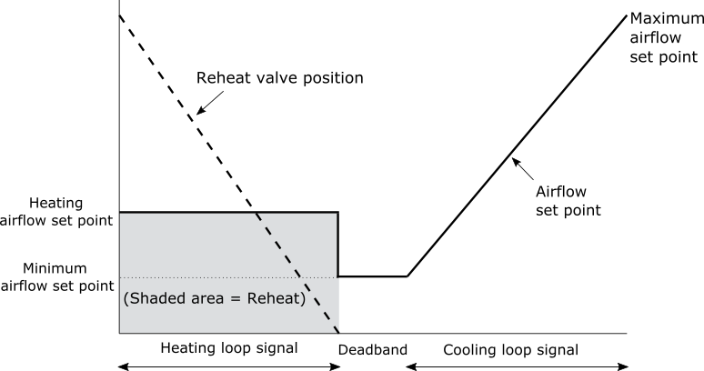
Controller for terminal VAV box with hot water reheat.
It is based on the control logic "dual maximum with constant volume heating" as
described in the Advanced VAV System Design Guide (EDR 2007).
The controller could be used for units with the pressure independent damper and the
units with the exponential damper, by setting the flag have_preIndDam.
Two separate control loops, the cooling loop and the heating loop, are implemented
to maintain space temperature within a temperature dead band (with a required minimum
width of 0.5 K).
For the terminal boxes with the pressure independent damper, the damper control
signal yDam corresponds to the discharge air flow rate
set point, normalized to the nominal value. While for the boxes with the exponential
damper, the damper position yDam is controlled by a PID loop to track the discharge
airflow setpoint.
The control signal for the reheat coil valve yVal corresponds to the
fractional opening (1 corresponding to the valve fully open).
For the termnal boxes with the pressure independent damper (have_preIndDam=true),
-
Inside the dead band,
yDamis fixed at the minimum valueratVFloMinandyValis 0. -
In heating demand,
yDamis fixed at the heating valueratVFloHea, andyValis modulated between 0 and 1. -
In cooling demand,
yDamis modulated between the minimum valueratVFloMinand 1, andyValis 0.
For the termnal boxes with the exponential damper (have_preIndDam=false),
-
Inside the dead band,
yDamis controlled to track the minimum valueratVFloMinandyValis 0. -
In heating demand,
yDamis controlled to track the heating valueratVFloHea, andyValis modulated between 0 and 1. -
In cooling demand,
yDamis controlled to track the airflow rate modulated between the minimum valueratVFloMinand 1, andyValis 0.
Note that a single maximum control logic can be represented by simply setting
ratVFloHea equal to ratVFloMin (default setting).
References
EDR (Energy Design Resources). Advanced Variable Air Volume System Design Guide. Pacific Gas and Electric Company, 2007.
Extends from Modelica.Blocks.Icons.Block (Basic graphical layout of input/output block).
Parameters
| Type | Name | Default | Description |
|---|---|---|---|
| Boolean | have_preIndDam | true | True: the terminal box has pressure independent damper |
| Real | ratVFloMin | 0.3 | Minimum airflow set point (ratio to nominal) [1] |
| Real | ratVFloHea | ratVFloMin | Heating airflow set point (ratio to nominal) [1] |
| VolumeFlowRate | V_flow_nominal | 0.1 | Norminal air volume flow rate [m3/s] |
| Cooling controller | |||
| SimpleController | cooController | Buildings.Controls.OBC.CDL.T... | Type of controller |
| Real | kCoo | 0.1 | Gain of controller |
| Time | TiCoo | 120 | Time constant of integrator block [s] |
| Time | TdCoo | 60 | Time constant of derivative block [s] |
| Heating controller | |||
| SimpleController | heaController | Buildings.Controls.OBC.CDL.T... | Type of controller |
| Real | kHea | 0.1 | Gain of controller |
| Time | TiHea | 120 | Time constant of integrator block [s] |
| Time | TdHea | 60 | Time constant of derivative block [s] |
| Damper controller | |||
| SimpleController | damController | Buildings.Controls.OBC.CDL.T... | Type of damper position controller |
| Real | kDam | 0.1 | Gain of controller |
| Time | TiDam | 120 | Time constant of integrator block [s] |
| Time | TdDam | 60 | Time constant of derivative block [s] |
Connectors
| Type | Name | Description |
|---|---|---|
| input RealInput | TRooHeaSet | Setpoint temperature for room for heating [K] |
| input RealInput | TRooCooSet | Setpoint temperature for room for cooling [K] |
| input RealInput | TRoo | Measured room temperature [K] |
| input RealInput | VDis_flow | Measured primary discharge airflow rate [m3/s] |
| output RealOutput | yDam | Signal for VAV damper |
| output RealOutput | yVal | Signal for heating coil valve |
Modelica definition
 Buildings.Examples.VAVReheat.BaseClasses.Controls.State
Block that outputs the mode if the state is active, or zero otherwise
Information
Extends from Modelica.StateGraph.StepWithSignal (Ordinary step (= step that is not active when simulation starts). Connector 'active' is true when the step is active).
Parameters
| Type | Name | Default | Description |
|---|---|---|---|
| OperationModes | mode | Enter enumeration of mode |
Connectors
| Type | Name | Description |
|---|---|---|
| Step_in | inPort[nIn] | Vector of step input connectors |
| Step_out | outPort[nOut] | Vector of step output connectors |
| output BooleanOutput | active | |
| output IntegerOutput | y | Mode signal (=0 if not active) |
Modelica definition
 Buildings.Examples.VAVReheat.BaseClasses.Controls.SupplyAirTemperature
Control block for tracking the supply air temperature set point
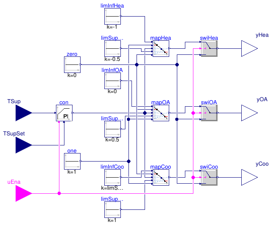
Information
This block implements the control logic for the supply air temperature, as described in the control sequence VAV 2A2-21232 of the Sequences of Operation for Common HVAC Systems (ASHRAE, 2006).
The heating coil valve, outdoor air damper, and cooling coil valve are modulated in sequence to maintain the supply air temperature set point. A deadband between heating and economizer cooling is also modeled.
Note that the economizer lockout when the outdoor air temperature is higher than the return air temperature is implemented in Buildings.Examples.VAVReheat.BaseClasses.Controls.Economizer.
References
ASHRAE. Sequences of Operation for Common HVAC Systems. ASHRAE, Atlanta, GA, 2006.
Extends from Modelica.Blocks.Icons.Block (Basic graphical layout of input/output block).
Parameters
| Type | Name | Default | Description |
|---|---|---|---|
| Boolean | have_heating | true | Set to true for heating and cooling functions (false for cooling only) |
| SimpleController | controllerType | Buildings.Controls.OBC.CDL.T... | Type of controller |
| Real | k | 0.01 | Gain of controller |
| Time | Ti | 120 | Time constant of integrator block [s] |
| Time | Td | 0.1 | Time constant of derivative block [s] |
Connectors
| Type | Name | Description |
|---|---|---|
| input BooleanInput | uEna | Signal enabling set point tracking |
| input RealInput | TSup | Supply air temperature measurement [K] |
| input RealInput | TSupSet | Supply air temperature set point [K] |
| output RealOutput | yHea | Control signal for heating coil valve [1] |
| output RealOutput | yOA | Control signal for outdoor air damper [1] |
| output RealOutput | yCoo | Control signal for cooling coil valve [1] |
Modelica definition
 Buildings.Examples.VAVReheat.BaseClasses.Controls.SupplyAirTemperatureSetpoint
Block computing the supply air temperature set point based on the operation mode
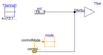
Information
This block computes the supply air temperature set point
based on the actual operating mode.
The default set point values are taken from the control sequence
VAV 2A2-21232 of the Sequences of Operation for
Common HVAC Systems (ASHRAE, 2006).
| Operating mode | Set point value [C] |
|---|---|
| Occupied | 12 |
| Unoccupied off | 12 |
| Unoccupied, night set back | 35 |
| Unoccupied, warm-up | 35 |
| Unoccupied, pre-cool | 12 |
| Safety | 7 |
References
ASHRAE. Sequences of Operation for Common HVAC Systems. ASHRAE, Atlanta, GA, 2006.
Extends from Modelica.Blocks.Icons.Block (Basic graphical layout of input/output block).
Connectors
| Type | Name | Description |
|---|---|---|
| ControlBus | controlBus | |
| output RealOutput | TSet | Supply air temperature set point [K] |
Modelica definition
 Buildings.Examples.VAVReheat.BaseClasses.Controls.SystemHysteresis
Block that applies hysteresis and a minimum on timer to a control signal
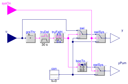
Information
Block that ensure that the system runs for a minimum time once it is switched on.
Connectors
| Type | Name | Description |
|---|---|---|
| input RealInput | u | Control signal |
| output RealOutput | y | Real output signal |
| output RealOutput | yPum | Control signal for pump |
| input BooleanInput | sysOn | System on signal, set for example to true if fan is on |