Buildings.DHC.Networks
Package of models for district energy distribution networks
Information
This package contains models for elements that form district energy distribution networks.
Extends from Modelica.Icons.VariantsPackage (Icon for package containing variants).
Package Content
| Name | Description |
|---|---|
| Model of a one-pipe distribution network with plug flow pipes in the main line with hydraulic diameter calculated from nominal velocity | |
| Model of a one-pipe distribution network with hydraulic diameter of main line pipes calculated from pressure drop per length | |
| Model of a two-pipe distribution network using plug flow pipe models in the main lines with hydraulic diameter calculated from nominal velocity | |
| Model of a two-pipe distribution network with hydraulic diameter of main line pipes calculated from pressure drop per length | |
| Package containing various configurations for connecting network participants to a distribution network | |
| Package of control blocks for distribution systems | |
| Package containing pipe models used within district network modeling | |
| Collection of models for distribution networks involving steam | |
| This package contains example models | |
| Package with base classes that are used by multiple models |
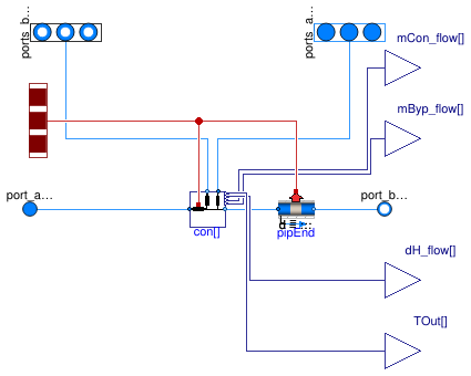
 Buildings.DHC.Networks.Distribution1PipePlugFlow_v
Model of a one-pipe distribution network with plug flow pipes in the main line with hydraulic diameter calculated from nominal velocity
Information
This model represents a one-pipe distribution network using a connection model with a plug flow pipe model (pressure drop, heat transfer, transport delays) in the main line whose hydraulic diameters are calculated based on nominal velocity at nominal flow rate Buildings.DHC.Networks.Connections.Connection1PipePlugFlow. The same pipe model at the end of the distribution line (after the last connection).
Extends from Buildings.DHC.Networks.BaseClasses.PartialDistribution1Pipe (Partial model for one-pipe distribution network).
Parameters
| Type | Name | Default | Description |
|---|---|---|---|
| Integer | nCon | Number of connections | |
| replaceable package Medium | PartialMedium | Medium model | |
| replaceable model Model_pipDis | Buildings.Fluid.FixedResista... | Model for distribution pipe | |
| Boolean | show_entFlo | false | Set to true to output enthalpy flow rate difference at each connection |
| Boolean | show_TOut | false | Set to true to output temperature at connection outlet |
| Length | lDis[nCon] | Length of the distribution pipe before each connection [m] | |
| Length | lEnd | Length of the end of the distribution line (after last connection) [m] | |
| Length | dIns | 0.05 | Thickness of pipe insulation, used to compute R [m] |
| ThermalConductivity | kIns | 0.028 | Heat conductivity of pipe insulation, used to compute R [W/(m.K)] |
| Velocity | v_nominal | 1.5 | Velocity at m_flow_nominal (used to compute default value for hydraulic diameter dh) [m/s] |
| Height | roughness | 2.5e-5 | Average height of surface asperities (default: smooth steel pipe) [m] |
| SpecificHeatCapacity | cPip | 2300 | Specific heat of pipe wall material. 2300 for PE, 500 for steel [J/(kg.K)] |
| Density | rhoPip | 930 | Density of pipe wall material. 930 for PE, 8000 for steel [kg/m3] |
| Length | thickness | 0.0035 | Pipe wall thickness [m] |
| Nominal condition | |||
| MassFlowRate | mDis_flow_nominal | Nominal mass flow rate in the distribution line [kg/s] | |
| MassFlowRate | mCon_flow_nominal[nCon] | Nominal mass flow rate in each connection line [kg/s] | |
| Assumptions | |||
| Boolean | allowFlowReversal | false | = true to allow flow reversal, false restricts to design direction (port_a -> port_b) |
| Dynamics | |||
| Conservation equations | |||
| Dynamics | energyDynamics | Modelica.Fluid.Types.Dynamic... | Type of energy balance: dynamic (3 initialization options) or steady state |
| Nominal condition | |||
| Time | tau | 5*60 | Time constant at nominal flow for dynamic energy and momentum balance [s] |
Connectors
| Type | Name | Description |
|---|---|---|
| FluidPorts_a | ports_aCon[nCon] | Connection return ports |
| FluidPorts_b | ports_bCon[nCon] | Connection supply ports |
| FluidPort_a | port_aDisSup | Distribution supply inlet port |
| FluidPort_b | port_bDisSup | Distribution supply outlet port |
| replaceable model Model_pipDis | Model for distribution pipe | |
| output RealOutput | dH_flow[nCon] | Difference in enthalpy flow rate between connection supply and return [W] |
| output RealOutput | mCon_flow[nCon] | Connection supply mass flow rate (measured) [kg/s] |
| output RealOutput | mByp_flow[nCon] | Bypass mass flow rate [kg/s] |
| output RealOutput | TOut[nCon] | Temperature in distribution line at each connection outlet [K] |
| HeatPorts_a | heatPorts[nCon + 1] | Multiple heat ports that connect to outside of pipe wall |
Modelica definition
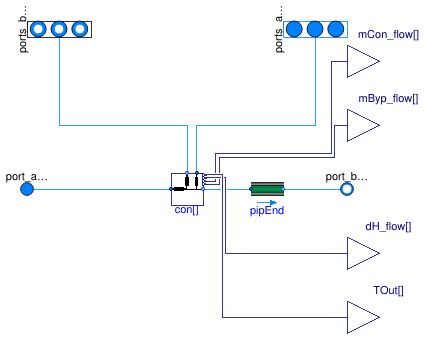
 Buildings.DHC.Networks.Distribution1Pipe_R
Model of a one-pipe distribution network with hydraulic diameter of main line pipes calculated from pressure drop per length
Information
This is a model of a one-pipe distribution network using a connection model with pipes in the main line whose hydraulic diameters are calculated at initialization based on the pressure drop per pipe length at nominal flow rate Buildings.DHC.Networks.Connections.Connection1Pipe_R. The same pipe model is also used at the end of the distribution line (after the last connection) only on the supply side.
Modeling considerations
Note that dhDis needs to be vectorized, even if the same value
is computed for each array element in case of a one-pipe network.
This is because the pipe diameter is computed at initialization by the model
Buildings.DHC.Networks.Pipes.PipeAutosize
which is instantiated for each connection.
So the initialization system of equations would be overdetermined if using
a parameter binding with a scalar variable.
Extends from Buildings.DHC.Networks.BaseClasses.PartialDistribution1Pipe (Partial model for one-pipe distribution network).
Parameters
| Type | Name | Default | Description |
|---|---|---|---|
| Integer | nCon | Number of connections | |
| replaceable package Medium | PartialMedium | Medium model | |
| replaceable model Model_pipDis | Buildings.DHC.Networks.Pipes... | Model for distribution pipe | |
| Boolean | show_entFlo | false | Set to true to output enthalpy flow rate difference at each connection |
| Boolean | show_TOut | false | Set to true to output temperature at connection outlet |
| Real | dp_length_nominal | 250 | Pressure drop per pipe length at nominal flow rate [Pa/m] |
| Length | lDis[nCon] | Length of the distribution pipe before each connection [m] | |
| Length | lEnd | Length of the end of the distribution line (after last connection) [m] | |
| Nominal condition | |||
| MassFlowRate | mDis_flow_nominal | Nominal mass flow rate in the distribution line [kg/s] | |
| MassFlowRate | mCon_flow_nominal[nCon] | Nominal mass flow rate in each connection line [kg/s] | |
| Assumptions | |||
| Boolean | allowFlowReversal | false | = true to allow flow reversal, false restricts to design direction (port_a -> port_b) |
| Dynamics | |||
| Conservation equations | |||
| Dynamics | energyDynamics | Modelica.Fluid.Types.Dynamic... | Type of energy balance: dynamic (3 initialization options) or steady state |
| Nominal condition | |||
| Time | tau | 5*60 | Time constant at nominal flow for dynamic energy and momentum balance [s] |
Connectors
| Type | Name | Description |
|---|---|---|
| FluidPorts_a | ports_aCon[nCon] | Connection return ports |
| FluidPorts_b | ports_bCon[nCon] | Connection supply ports |
| FluidPort_a | port_aDisSup | Distribution supply inlet port |
| FluidPort_b | port_bDisSup | Distribution supply outlet port |
| replaceable model Model_pipDis | Model for distribution pipe | |
| output RealOutput | dH_flow[nCon] | Difference in enthalpy flow rate between connection supply and return [W] |
| output RealOutput | mCon_flow[nCon] | Connection supply mass flow rate (measured) [kg/s] |
| output RealOutput | mByp_flow[nCon] | Bypass mass flow rate [kg/s] |
| output RealOutput | TOut[nCon] | Temperature in distribution line at each connection outlet [K] |
Modelica definition
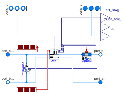
 Buildings.DHC.Networks.Distribution2PipePlugFlow_v
Model of a two-pipe distribution network using plug flow pipe models in the main lines with hydraulic diameter calculated from nominal velocity
Information
This is a model of a two-pipe distribution network using a connection model with a plug flow pipe model (pressure drop, heat transfer, transport delays) in the main lines whose hydraulic diameters are calculated based on nominal velocity at nominal flow rate Buildings.DHC.Networks.Connections.Connection2PipePlugFlow. The same pipe model is also used at the end of the distribution line (after the last connection) only on the supply side.
Extends from Buildings.DHC.Networks.BaseClasses.PartialDistribution2Pipe (Partial model for two-pipe distribution network).
Parameters
| Type | Name | Default | Description |
|---|---|---|---|
| Integer | nCon | Number of connections | |
| replaceable package Medium | PartialMedium | Medium model | |
| replaceable model Model_pipDis | Buildings.Fluid.FixedResista... | Model for distribution pipe | |
| Integer | iConDpSen | nCon | Index of the connection where the pressure drop is measured |
| Boolean | show_entFlo | false | Set to true to output enthalpy flow rate difference at each connection |
| Length | lDis[nCon] | Length of the distribution pipe before each connection (supply only, not counting return line) [m] | |
| Length | lEnd | Length of the end of the distribution line (supply only, not counting return line) [m] | |
| Length | dIns | 0.05 | Thickness of pipe insulation, used to compute R [m] |
| ThermalConductivity | kIns | 0.028 | Heat conductivity of pipe insulation, used to compute R [W/(m.K)] |
| Velocity | v_nominal | 1.5 | Velocity at m_flow_nominal (used to compute default value for hydraulic diameter dh) [m/s] |
| Height | roughness | 2.5e-5 | Average height of surface asperities (default: smooth steel pipe) [m] |
| SpecificHeatCapacity | cPip | 2300 | Specific heat of pipe wall material. 2300 for PE, 500 for steel [J/(kg.K)] |
| Density | rhoPip | 930 | Density of pipe wall material. 930 for PE, 8000 for steel [kg/m3] |
| Length | thickness | 0.0035 | Pipe wall thickness [m] |
| Nominal condition | |||
| MassFlowRate | mDis_flow_nominal | Nominal mass flow rate in the distribution line before the first connection [kg/s] | |
| MassFlowRate | mCon_flow_nominal[nCon] | Nominal mass flow rate in each connection line [kg/s] | |
| MassFlowRate | mEnd_flow_nominal | mDis_flow_nominal - sum(mCon... | Nominal mass flow rate in the end of the distribution line [kg/s] |
| MassFlowRate | mDisCon_flow_nominal[nCon] | cat(1, {mDis_flow_nominal}, ... | Nominal mass flow rate in the distribution line before each connection [kg/s] |
| Assumptions | |||
| Boolean | allowFlowReversal | false | = true to allow flow reversal, false restricts to design direction (port_a -> port_b) |
| Dynamics | |||
| Conservation equations | |||
| Dynamics | energyDynamics | Modelica.Fluid.Types.Dynamic... | Type of energy balance: dynamic (3 initialization options) or steady state |
| Nominal condition | |||
| Time | tau | 10 | Time constant at nominal flow for dynamic energy and momentum balance [s] |
Connectors
| Type | Name | Description |
|---|---|---|
| FluidPorts_a | ports_aCon[nCon] | Connection return ports |
| FluidPorts_b | ports_bCon[nCon] | Connection supply ports |
| FluidPort_a | port_aDisSup | Distribution supply inlet port |
| FluidPort_b | port_bDisSup | Distribution supply outlet port |
| replaceable model Model_pipDis | Model for distribution pipe | |
| FluidPort_b | port_bDisRet | Distribution return outlet port |
| FluidPort_a | port_aDisRet | Distribution return inlet port |
| output RealOutput | dp | Pressure difference at given location (measured) [Pa] |
| output RealOutput | dH_flow[nCon] | Difference in enthalpy flow rate between connection supply and return [W] |
| output RealOutput | mCon_flow[nCon] | Connection supply mass flow rate (measured) [kg/s] |
| HeatPorts_a | heatPortsDis[nCon + 1] | Multiple heat ports that connect to outside of pipe wall for distribution pipe |
| HeatPorts_a | heatPortsRet[nCon] | Multiple heat ports that connect to outside of pipe wall for return pipe |
Modelica definition
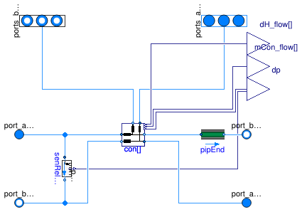
 Buildings.DHC.Networks.Distribution2Pipe_R
Model of a two-pipe distribution network with hydraulic diameter of main line pipes calculated from pressure drop per length
Information
This is a model of a two-pipe distribution network using a connection model with pipes in the main lines whose hydraulic diameters are calculated at initialization based on the pressure drop per pipe length at nominal flow rate Buildings.DHC.Networks.Connections.Connection2Pipe_R. The same pipe model is also used at the end of the distribution line (after the last connection) only on the supply side.
Modeling considerations
Note that dhDis needs to be vectorized, even if the same value
is computed for each array element in case of a one-pipe network.
This is because the pipe diameter is computed at initialization by the model
Buildings.DHC.Networks.Pipes.PipeAutosize
which is instantiated for each connection.
So the initialization system of equations would be overdetermined if using
a parameter binding with a scalar variable.
Extends from Buildings.DHC.Networks.BaseClasses.PartialDistribution2Pipe (Partial model for two-pipe distribution network).
Parameters
| Type | Name | Default | Description |
|---|---|---|---|
| Integer | nCon | Number of connections | |
| replaceable package Medium | PartialMedium | Medium model | |
| replaceable model Model_pipDis | Buildings.DHC.Networks.Pipes... | Model for distribution pipe | |
| Integer | iConDpSen | nCon | Index of the connection where the pressure drop is measured |
| Boolean | show_entFlo | false | Set to true to output enthalpy flow rate difference at each connection |
| Real | dp_length_nominal | 250 | Pressure drop per pipe length at nominal flow rate [Pa/m] |
| Length | lDis[nCon] | Length of the distribution pipe before each connection (supply only, not counting return line) [m] | |
| Length | lEnd | Length of the end of the distribution line (supply only, not counting return line) [m] | |
| Nominal condition | |||
| MassFlowRate | mDis_flow_nominal | Nominal mass flow rate in the distribution line before the first connection [kg/s] | |
| MassFlowRate | mCon_flow_nominal[nCon] | Nominal mass flow rate in each connection line [kg/s] | |
| MassFlowRate | mEnd_flow_nominal | mDis_flow_nominal - sum(mCon... | Nominal mass flow rate in the end of the distribution line [kg/s] |
| MassFlowRate | mDisCon_flow_nominal[nCon] | cat(1, {mDis_flow_nominal}, ... | Nominal mass flow rate in the distribution line before each connection [kg/s] |
| Assumptions | |||
| Boolean | allowFlowReversal | false | = true to allow flow reversal, false restricts to design direction (port_a -> port_b) |
| Dynamics | |||
| Conservation equations | |||
| Dynamics | energyDynamics | Modelica.Fluid.Types.Dynamic... | Type of energy balance: dynamic (3 initialization options) or steady state |
| Nominal condition | |||
| Time | tau | 5*60 | Time constant at nominal flow for dynamic energy and momentum balance [s] |
Connectors
| Type | Name | Description |
|---|---|---|
| FluidPorts_a | ports_aCon[nCon] | Connection return ports |
| FluidPorts_b | ports_bCon[nCon] | Connection supply ports |
| FluidPort_a | port_aDisSup | Distribution supply inlet port |
| FluidPort_b | port_bDisSup | Distribution supply outlet port |
| replaceable model Model_pipDis | Model for distribution pipe | |
| FluidPort_b | port_bDisRet | Distribution return outlet port |
| FluidPort_a | port_aDisRet | Distribution return inlet port |
| output RealOutput | dp | Pressure difference at given location (measured) [Pa] |
| output RealOutput | dH_flow[nCon] | Difference in enthalpy flow rate between connection supply and return [W] |
| output RealOutput | mCon_flow[nCon] | Connection supply mass flow rate (measured) [kg/s] |