Buildings.Fluid.HydronicConfigurations.ActiveNetworks
Package of hydronic configurations for active networks
Information
This package contains models of hydronic configurations compatible with active primary networks.
Extends from Modelica.Icons.VariantsPackage (Icon for package containing variants).
Package Content
| Name | Description |
|---|---|
| Decoupling circuit with self-acting Delta-p control valve | |
| Diversion circuit | |
| Injection circuit with three-way valve | |
| Injection circuit with two-way valve | |
| Injection circuit with two-way valve and check valve in bypass branch | |
| Single mixing circuit | |
| Throttle circuit | |
| Example models |
 Buildings.Fluid.HydronicConfigurations.ActiveNetworks.Decoupling
Decoupling circuit with self-acting Delta-p control valve
Information
Summary
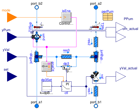
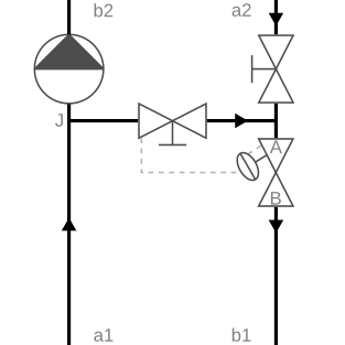
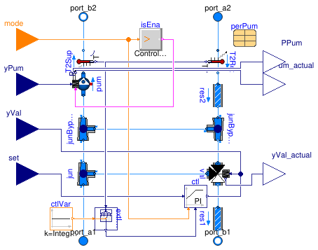
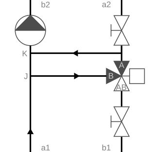
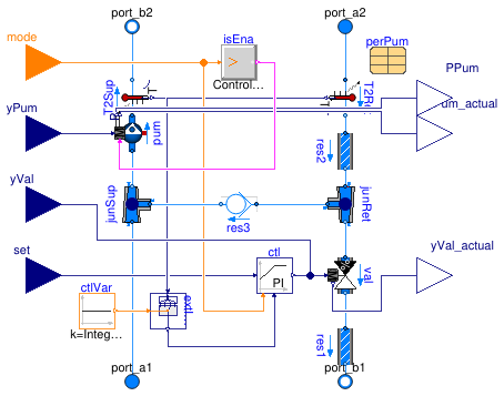
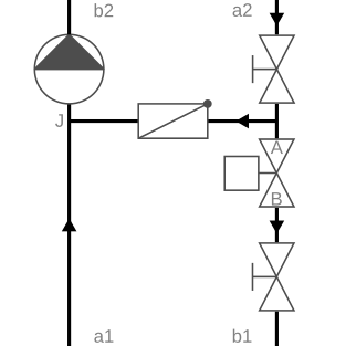
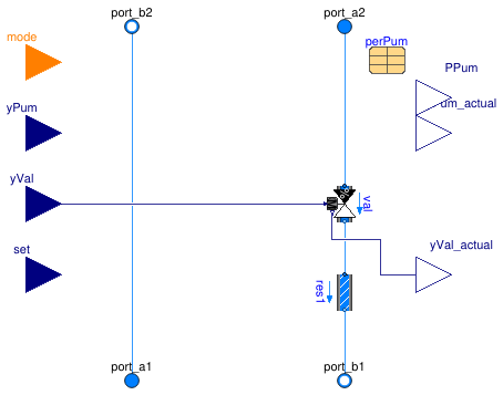
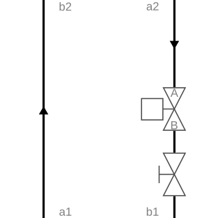
This configuration (see schematic below) is used for variable flow primary and consumer circuits where the consumer circuit has the same supply temperature set point as the primary circuit. The fixed bypass prevents the primary pressure differential from being transmitted to the consumer circuit. This allows a proper operation of the terminal control valves on the consumer side when the primary pressure differential is either too low or too high or varying too much. The self-acting Δp control valve maintains a nearly constant bypass mass flow rate, set by default to 5% of the consumer circuit design mass flow rate.
The following table presents the main characteristics of this configuration.
| Primary circuit | Variable flow |
| Secondary (consumer) circuit | Variable flow |
| Typical applications |
Same consumer circuit supply temperature set point as primary circuit (Otherwise use either this model in conjunction with Buildings.Fluid.HydronicConfigurations.PassiveNetworks.SingleMixing, or Buildings.Fluid.HydronicConfigurations.ActiveNetworks.InjectionTwoWay) Primary pressure differential either too low or too high or varying too much such as in DHC systems |
| Non-recommended applications |
Heating systems with condensing boilers due to the recirculating primary flow rate (Since the recirculating primary flow rate is controlled to a nearly constant value, this configuration is used in DHC systems.) |
| Built-in valve control options | Self-acting Δp control valve with a proportional band of ±20% around the pressure differential set point |
|
Control valve selection (See the nomenclature in the schematic.) |
β = ΔpA-B /
(Δp1 + ΔpA-J)
≈ ΔpA-B / Δp1 The valve is sized with a pressure drop of Δp1 / 2 for a mass flow rate 5 to 10% higher than m2_flow_nominal.
|
| Balancing requirement |
The design pressure drop of the bypass balancing valve
dpBal3_nominal is typically around 10 kPa
for a mass flow rate of m1_flow_nominal-m2_flow_nominal.
No primary balancing valve is needed in addition to the self-acting
Δp control valve.(For an actuated control valve with external controls, the same balancing requirements as for Buildings.Fluid.HydronicConfigurations.ActiveNetworks.InjectionTwoWay hold. No bypass balancing valve is needed.) |
|
Lumped flow resistance includes (With the setting use_lumFloRes=true.)
|
Control valve val and primary balancing valve res1
|
Additional comments
The P-controller used in the model mimics a self-acting Δp control valve with a proportional band of ±20% around the pressure differential set point. This set point corresponds to the design pressure drop of the bypass balancing valve. Note that this configuration yields a nearly constant bypass mass flow rate, as opposed to a constant percentage of the consumer circuit mass flow rate provided by a control based on the return temperature upstream and downstream of the bypass. However, as illustrated in Buildings.Fluid.HydronicConfigurations.ActiveNetworks.Examples.DecouplingTemperature the latter control logic is flawed at low load, and the primary mass flow rate potentially maxed out. Since there is no standard strategy to counteract that effect, the configuration with built-in controls based on return temperature is not included in this package.
The specific built-in control option implemented in this model does not
depend on the actual function of the consumer circuit
(such as cooling, heating, or change-over).
Therefore, the model remains the same whatever the value
assigned to the parameter typCtl except if
None (no built-in controls) is selected.
In that latter case only, no built-in controls are included and the user
must connect a control signal to modulate the valve.
For consumer circuits with a different supply temperature set point, this configuration is sometimes used in conjunction with Buildings.Fluid.HydronicConfigurations.PassiveNetworks.SingleMixing, see the example Buildings.Fluid.HydronicConfigurations.ActiveNetworks.Examples.DecouplingMixing.
Extends from Fluid.HydronicConfigurations.Interfaces.PartialHydronicConfiguration.
Parameters
| Type | Name | Default | Description |
|---|---|---|---|
| replaceable package Medium | Water | Medium in the component | |
| Configuration | |||
| Boolean | use_siz | true | Set to true for built-in sizing of control valve and optional pump |
| Boolean | use_dp1 | use_siz | Set to true to enable dp1_nominal |
| Boolean | use_dp2 | use_siz and typPum <> Buildi... | Set to true to enable dp2_nominal |
| Valve | typVal | Buildings.Fluid.HydronicConf... | Type of control valve |
| Boolean | have_typVar | false | Set to true to enable the choice of the controlled variable |
| Nominal condition | |||
| MassFlowRate | m2_flow_nominal | Mass flow rate in consumer circuit at design conditions [kg/s] | |
| PressureDifference | dp1_nominal | Primary circuit pressure differential at design conditions [Pa] | |
| PressureDifference | dp2_nominal | Consumer circuit pressure differential at design conditions [Pa] | |
| Control valve | |||
| ValveCharacteristic | typCha | Buildings.Fluid.HydronicConf... | Control valve characteristic |
| PressureDifference | dpValve_nominal | dp1_nominal/2 | Control valve pressure drop at design conditions [Pa] |
| Generic | flowCharacteristics | Table with flow characteristics | |
| Generic | flowCharacteristics1 | Table with flow characteristics for direct flow path at port_1 | |
| Generic | flowCharacteristics3 | Table with flow characteristics for bypass flow path at port_3 | |
| Pump | |||
| Pump | typPum | Buildings.Fluid.HydronicConf... | Type of secondary pump |
| PumpModel | typPumMod | Buildings.Fluid.HydronicConf... | Type of pump model |
| MassFlowRate | mPum_flow_nominal | m2_flow_nominal | Pump head at design conditions [kg/s] |
| PressureDifference | dpPum_nominal | dp2_nominal + dpBal2_nominal | Pump head at design conditions [Pa] |
| Generic | perPum | redeclare parameter Movers.D... | Pump parameters |
| Controls | |||
| Control | typCtl | Buildings.Fluid.HydronicConf... | Type of built-in controls |
| ControlVariable | typVar | Buildings.Fluid.HydronicConf... | Controlled variable |
| SimpleController | controllerType | Buildings.Controls.OBC.CDL.T... | Type of controller |
| Real | k | 5 | Gain of controller |
| Real | Ti | 120 | Time constant of integrator block [s] |
| Balancing valves | |||
| PressureDifference | dpBal1_nominal | 0 | Primary balancing valve pressure drop at design conditions [Pa] |
| PressureDifference | dpBal2_nominal | 0 | Secondary balancing valve pressure drop at design conditions [Pa] |
| PressureDifference | dpBal3_nominal | if typCtl <> Buildings.Fluid... | Bypass balancing valve pressure drop at design conditions [Pa] |
| Assumptions | |||
| Boolean | use_lumFloRes | true | Set to true to use a lumped flow resistance when possible |
| Boolean | allowFlowReversal | true | = false to simplify equations, assuming, but not enforcing, no flow reversal for medium 1 |
| Dynamics | |||
| Conservation equations | |||
| Dynamics | energyDynamics | Modelica.Fluid.Types.Dynamic... | Type of energy balance: dynamic (3 initialization options) or steady state |
| Advanced | |||
| Diagnostics | |||
| Boolean | show_T | false | = true, if actual temperature at port is computed |
Connectors
| Type | Name | Description |
|---|---|---|
| FluidPort_a | port_a1 | Primary supply port |
| FluidPort_b | port_b1 | Primary return port |
| FluidPort_a | port_a2 | Secondary return port |
| FluidPort_b | port_b2 | Secondary supply port |
| input RealInput | yVal | Valve control signal [1] |
| input RealInput | set | Set point |
| input RealInput | yPum | Pump control signal (variable speed) [1] |
| input IntegerInput | mode | Operating mode |
| output RealOutput | yVal_actual | Valve position feedback [1] |
| output RealOutput | yPum_actual | Actual pump input value that is used for computations [1] |
| output RealOutput | PPum | Pump electrical power [W] |
Modelica definition
 Buildings.Fluid.HydronicConfigurations.ActiveNetworks.Diversion
Diversion circuit
Information
Summary
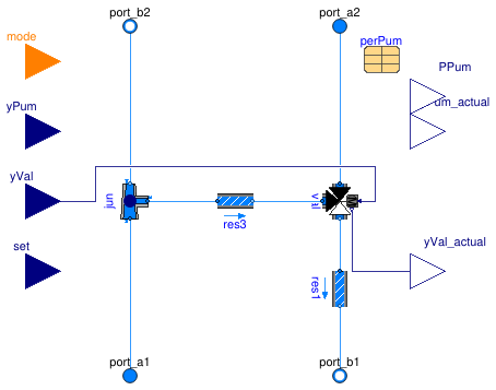
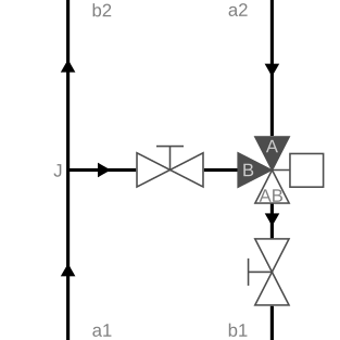
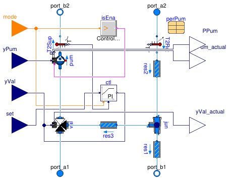
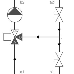
This configuration (see schematic below) is used for constant flow primary circuits and variable flow consumer circuits where the consumer circuit has the same supply temperature set point as the primary circuit.
The following table presents the main characteristics of this configuration.
| Primary circuit | Constant flow |
| Secondary (consumer) circuit | Variable flow |
| Typical applications | Single heating or cooling coil served by a constant flow circuit |
| Non-recommended applications |
DHC systems due to the significant recirculating primary flow rate at low load Heating systems with condensing boilers for the same reason |
| Built-in valve control options | No built-in controls |
| Control valve selection |
β = ΔpA-AB /
(Δp2 + ΔpA-AB) =
ΔpA-AB /
(Δp1 - ΔpAB-b1) The valve is sized with a pressure drop of Δp2 for a mass flow rate equal to the consumer circuit design flow. |
| Balancing requirement | The bypass balancing valve is not needed in most cases. If the valve has a low authority and the consumer circuit has a high pressure drop (compared to the primary pump head) then a bypass balancing valve should be used and sized so that ΔpJ-B + ΔpB-AB = Δp2 + ΔpA-AB for a mass flow rate equal to the consumer circuit design flow. |
|
Lumped flow resistances include (With the setting use_lumFloRes=true.)
|
Direct branch: control valve direct branch val.res1
and whole consumer circuit between b2 and a2Bypass branch: control valve bypass branch val.res3
and bypass balancing valve res3
|
Additional comments
See the example Buildings.Fluid.HydronicConfigurations.ActiveNetworks.Examples.DiversionOpenLoop for additional comments regarding the need for a balanced bypass.
Extends from Fluid.HydronicConfigurations.Interfaces.PartialHydronicConfiguration.
Parameters
| Type | Name | Default | Description |
|---|---|---|---|
| replaceable package Medium | Water | Medium in the component | |
| Configuration | |||
| Boolean | use_siz | true | Set to true for built-in sizing of control valve and optional pump |
| Boolean | use_dp1 | false | Set to true to enable dp1_nominal |
| Boolean | use_dp2 | use_lumFloRes or use_siz | Set to true to enable dp2_nominal |
| Valve | typVal | Buildings.Fluid.HydronicConf... | Type of control valve |
| Boolean | have_typVar | false | Set to true to enable the choice of the controlled variable |
| Nominal condition | |||
| MassFlowRate | m1_flow_nominal | m2_flow_nominal | Mass flow rate in primary circuit at design conditions [kg/s] |
| MassFlowRate | m2_flow_nominal | Mass flow rate in consumer circuit at design conditions [kg/s] | |
| PressureDifference | dp1_nominal | Primary circuit pressure differential at design conditions [Pa] | |
| PressureDifference | dp2_nominal | Consumer circuit pressure differential at design conditions [Pa] | |
| Control valve | |||
| ValveCharacteristic | typCha | Buildings.Fluid.HydronicConf... | Control valve characteristic |
| PressureDifference | dpValve_nominal | dp2_nominal | Control valve pressure drop at design conditions [Pa] |
| Generic | flowCharacteristics | Table with flow characteristics | |
| Generic | flowCharacteristics1 | Table with flow characteristics for direct flow path at port_1 | |
| Generic | flowCharacteristics3 | Table with flow characteristics for bypass flow path at port_3 | |
| Pump | |||
| Pump | typPum | Buildings.Fluid.HydronicConf... | Type of secondary pump |
| PumpModel | typPumMod | Buildings.Fluid.HydronicConf... | Type of pump model |
| MassFlowRate | mPum_flow_nominal | m2_flow_nominal | Pump head at design conditions [kg/s] |
| PressureDifference | dpPum_nominal | dp2_nominal + dpBal2_nominal | Pump head at design conditions [Pa] |
| Generic | perPum | redeclare parameter Movers.D... | Pump parameters |
| Controls | |||
| Control | typCtl | Buildings.Fluid.HydronicConf... | Type of built-in controls |
| ControlVariable | typVar | Buildings.Fluid.HydronicConf... | Controlled variable |
| SimpleController | controllerType | Buildings.Controls.OBC.CDL.T... | Type of controller |
| Real | k | 0.1 | Gain of controller |
| Real | Ti | 120 | Time constant of integrator block [s] |
| Balancing valves | |||
| PressureDifference | dpBal1_nominal | 0 | Primary balancing valve pressure drop at design conditions [Pa] |
| PressureDifference | dpBal2_nominal | 0 | Secondary balancing valve pressure drop at design conditions [Pa] |
| PressureDifference | dpBal3_nominal | 0 | Bypass balancing valve pressure drop at design conditions [Pa] |
| Assumptions | |||
| Boolean | use_lumFloRes | true | Set to true to use a lumped flow resistance when possible |
| Boolean | allowFlowReversal | true | = false to simplify equations, assuming, but not enforcing, no flow reversal for medium 1 |
| Dynamics | |||
| Conservation equations | |||
| Dynamics | energyDynamics | Modelica.Fluid.Types.Dynamic... | Type of energy balance: dynamic (3 initialization options) or steady state |
| Advanced | |||
| Diagnostics | |||
| Boolean | show_T | false | = true, if actual temperature at port is computed |
Connectors
| Type | Name | Description |
|---|---|---|
| FluidPort_a | port_a1 | Primary supply port |
| FluidPort_b | port_b1 | Primary return port |
| FluidPort_a | port_a2 | Secondary return port |
| FluidPort_b | port_b2 | Secondary supply port |
| input RealInput | yVal | Valve control signal [1] |
| input RealInput | set | Set point |
| input RealInput | yPum | Pump control signal (variable speed) [1] |
| input IntegerInput | mode | Operating mode |
| output RealOutput | yVal_actual | Valve position feedback [1] |
| output RealOutput | yPum_actual | Actual pump input value that is used for computations [1] |
| output RealOutput | PPum | Pump electrical power [W] |
Modelica definition
 Buildings.Fluid.HydronicConfigurations.ActiveNetworks.InjectionThreeWay
Injection circuit with three-way valve
Information
Summary
This configuration (see schematic below) is used for constant flow primary and consumer circuits where the consumer circuit has a different supply temperature set point, either at design conditions or varying during operation. Although this configuration may theoretically still be used if the primary and secondary design temperatures are equal, it loses its main advantage which is that the control valve can be sized for a lower flow rate and can therefore be smaller. The fixed bypass ensures a consumer circuit operation hydronically decoupled from the primary side and the control valve position.
The following table presents the main characteristics of this configuration.
| Primary circuit | Constant flow |
| Secondary (consumer) circuit | Constant flow |
| Typical applications |
Consumer circuit supply temperature different from primary circuit such
as underfloor heating systems (Otherwise use Buildings.Fluid.HydronicConfigurations.ActiveNetworks.Decoupling) Primary pressure differential either too low or too high or varying too much |
| Non-recommended applications |
DHC systems due to the significant recirculating primary flow rate at low load Heating systems with condensing boilers for the same reason |
| Built-in valve control options |
Supply temperature Return temperature |
|
Control valve selection |
β
= ΔpA-AB / ΔpJ-AB
≈ 1 Sizing is only based on a minimum pressure drop of 3 kPa at design flow rate ṁ1, design (see below). |
| Balancing requirement |
The three-way valve should be fully open at design conditions.dpBal3_nominal=dp1_nominal-dpValve_nominal
for the primary design flow rate
ṁ1, design = ṁ2, design *
(T2, sup, design - T2, ret, design) /
(T1, sup, design - T2, ret, design)
|
|
Lumped flow resistances include (With the setting use_lumFloRes=true.)
|
Control valve val only(So the option has no effect here: the balancing valves are always modeled as distinct flow resistances.) |
Additional comments
The reduced flow through the control valve due to the intermediary bypass allows selecting a smaller valve for the same design pressure drop. The pressure drop through the control valve is compensated by the primary pump, reducing the secondary pump head.
The balancing procedure should ensure that the three-way valve is fully open at design conditions. Oversizing the primary balancing valve (yielding a lower pressure drop) is not detrimental to the consumer circuit operation: the control valve compensates by working at a lower opening fraction on average. However, the primary circuit operation is degraded with a lower ΔT and a higher mass flow rate. See Buildings.Fluid.HydronicConfigurations.ActiveNetworks.Examples.InjectionThreeWay for a numerical illustration of those effects.
Extends from Fluid.HydronicConfigurations.Interfaces.PartialHydronicConfiguration.
Parameters
| Type | Name | Default | Description |
|---|---|---|---|
| replaceable package Medium | Water | Medium in the component | |
| Configuration | |||
| Boolean | use_siz | true | Set to true for built-in sizing of control valve and optional pump |
| Boolean | use_dp1 | false | Set to true to enable dp1_nominal |
| Boolean | use_dp2 | use_siz and typPum <> Buildi... | Set to true to enable dp2_nominal |
| Valve | typVal | Buildings.Fluid.HydronicConf... | Type of control valve |
| Boolean | have_typVar | true | Set to true to enable the choice of the controlled variable |
| Nominal condition | |||
| MassFlowRate | m1_flow_nominal | Mass flow rate in primary circuit at design conditions [kg/s] | |
| MassFlowRate | m2_flow_nominal | Mass flow rate in consumer circuit at design conditions [kg/s] | |
| PressureDifference | dp1_nominal | Primary circuit pressure differential at design conditions [Pa] | |
| PressureDifference | dp2_nominal | Consumer circuit pressure differential at design conditions [Pa] | |
| Control valve | |||
| ValveCharacteristic | typCha | Buildings.Fluid.HydronicConf... | Control valve characteristic |
| PressureDifference | dpValve_nominal | 3e3 | Control valve pressure drop at design conditions [Pa] |
| Generic | flowCharacteristics | Table with flow characteristics | |
| Generic | flowCharacteristics1 | Table with flow characteristics for direct flow path at port_1 | |
| Generic | flowCharacteristics3 | Table with flow characteristics for bypass flow path at port_3 | |
| Pump | |||
| Pump | typPum | Buildings.Fluid.HydronicConf... | Type of secondary pump |
| PumpModel | typPumMod | Buildings.Fluid.HydronicConf... | Type of pump model |
| MassFlowRate | mPum_flow_nominal | m2_flow_nominal | Pump head at design conditions [kg/s] |
| PressureDifference | dpPum_nominal | dp2_nominal + dpBal2_nominal | Pump head at design conditions [Pa] |
| Generic | perPum | redeclare parameter Movers.D... | Pump parameters |
| Controls | |||
| Control | typCtl | Buildings.Fluid.HydronicConf... | Type of built-in controls |
| ControlVariable | typVar | Buildings.Fluid.HydronicConf... | Controlled variable |
| SimpleController | controllerType | Buildings.Controls.OBC.CDL.T... | Type of controller |
| Real | k | 0.1 | Gain of controller |
| Real | Ti | 120 | Time constant of integrator block [s] |
| Balancing valves | |||
| PressureDifference | dpBal1_nominal | 0 | Primary balancing valve pressure drop at design conditions [Pa] |
| PressureDifference | dpBal2_nominal | 0 | Secondary balancing valve pressure drop at design conditions [Pa] |
| PressureDifference | dpBal3_nominal | 0 | Bypass balancing valve pressure drop at design conditions [Pa] |
| Assumptions | |||
| Boolean | use_lumFloRes | true | Set to true to use a lumped flow resistance when possible |
| Boolean | allowFlowReversal | true | = false to simplify equations, assuming, but not enforcing, no flow reversal for medium 1 |
| Dynamics | |||
| Conservation equations | |||
| Dynamics | energyDynamics | Modelica.Fluid.Types.Dynamic... | Type of energy balance: dynamic (3 initialization options) or steady state |
| Advanced | |||
| Diagnostics | |||
| Boolean | show_T | false | = true, if actual temperature at port is computed |
Connectors
| Type | Name | Description |
|---|---|---|
| FluidPort_a | port_a1 | Primary supply port |
| FluidPort_b | port_b1 | Primary return port |
| FluidPort_a | port_a2 | Secondary return port |
| FluidPort_b | port_b2 | Secondary supply port |
| input RealInput | yVal | Valve control signal [1] |
| input RealInput | set | Set point [K] |
| input RealInput | yPum | Pump control signal (variable speed) [1] |
| input IntegerInput | mode | Operating mode |
| output RealOutput | yVal_actual | Valve position feedback [1] |
| output RealOutput | yPum_actual | Actual pump input value that is used for computations [1] |
| output RealOutput | PPum | Pump electrical power [W] |
Modelica definition
 Buildings.Fluid.HydronicConfigurations.ActiveNetworks.InjectionTwoWay
Injection circuit with two-way valve
Information
Summary
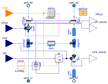
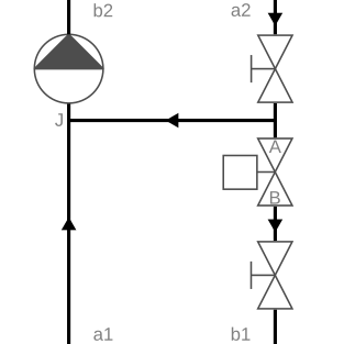
This circuit (see schematic hereunder) is used for variable flow primary circuits and either constant flow or variable flow consumer circuits. The fixed bypass prevents the primary pressure differential from being transmitted to the consumer circuit. This allows a proper operation of the terminal control valves on the consumer side when the primary pressure differential is either too low or too high or varying too much. For variable flow consumer circuits, the supply temperature set point must be different from the primary circuit.
The following table presents the main characteristics of this configuration.
| Primary circuit |
Variable flow (See caveats in Buildings.Fluid.HydronicConfigurations.ActiveNetworks.Examples.InjectionTwoWayConstant: control options are critical to achieve a truly variable flow.) |
| Secondary (consumer) circuit | Constant or variable flow |
| Typical applications |
Consumer circuit supply temperature set point different from primary circuit (Otherwise use Buildings.Fluid.HydronicConfigurations.ActiveNetworks.Decoupling) Primary pressure differential either too low or too high or varying too much such as in DHC systems |
| Non-recommended applications |
Variable flow consumer circuit with same supply temperature set point as primary circuit, see
Buildings.Fluid.HydronicConfigurations.ActiveNetworks.Examples.InjectionTwoWayVariable Variable flow consumer circuit with return temperature control, see Buildings.Fluid.HydronicConfigurations.ActiveNetworks.Examples.InjectionTwoWayVariableReturn |
| Built-in valve control options |
Supply temperature (must be different from primary) Return temperature (incompatible with variable secondary) |
|
Control valve selection (See the nomenclature in the schematic.) |
β = ΔpA-B / Δp1 The valve is sized with a pressure drop of Δp1 / 2 which yields an authority of 0.5. |
| Balancing requirement |
dpBal1_nominal=dp1_nominal-dpValve_nominal
for the primary design flow rate
ṁ1, design = ṁ2, design *
(T2, sup, design - T2, ret, design) /
(T1, sup, design - T2, ret, design)
|
|
Lumped flow resistance includes (With the setting use_lumFloRes=true.)
|
Control valve val and primary balancing valve res1
|
Additional comments
The pressure drop through the control valve is compensated by the primary pump, reducing the secondary pump head.
Extends from HydronicConfigurations.Interfaces.PartialHydronicConfiguration.
Parameters
| Type | Name | Default | Description |
|---|---|---|---|
| replaceable package Medium | Water | Medium in the component | |
| LosslessPipe | res3 | res3(redeclare final package... | Fluid pass-through that can be replaced by check valve |
| Configuration | |||
| Boolean | use_siz | true | Set to true for built-in sizing of control valve and optional pump |
| Boolean | use_dp1 | use_siz | Set to true to enable dp1_nominal |
| Boolean | use_dp2 | use_siz and typPum <> Buildi... | Set to true to enable dp2_nominal |
| Valve | typVal | Buildings.Fluid.HydronicConf... | Type of control valve |
| Boolean | have_typVar | true | Set to true to enable the choice of the controlled variable |
| Nominal condition | |||
| MassFlowRate | m1_flow_nominal | Mass flow rate in primary circuit at design conditions [kg/s] | |
| MassFlowRate | m2_flow_nominal | Mass flow rate in consumer circuit at design conditions [kg/s] | |
| PressureDifference | dp1_nominal | Primary circuit pressure differential at design conditions [Pa] | |
| PressureDifference | dp2_nominal | Consumer circuit pressure differential at design conditions [Pa] | |
| Control valve | |||
| ValveCharacteristic | typCha | Buildings.Fluid.HydronicConf... | Control valve characteristic |
| PressureDifference | dpValve_nominal | dp1_nominal/2 | Control valve pressure drop at design conditions [Pa] |
| Generic | flowCharacteristics | Table with flow characteristics | |
| Generic | flowCharacteristics1 | Table with flow characteristics for direct flow path at port_1 | |
| Generic | flowCharacteristics3 | Table with flow characteristics for bypass flow path at port_3 | |
| Pump | |||
| Pump | typPum | Buildings.Fluid.HydronicConf... | Type of secondary pump |
| PumpModel | typPumMod | Buildings.Fluid.HydronicConf... | Type of pump model |
| MassFlowRate | mPum_flow_nominal | m2_flow_nominal | Pump head at design conditions [kg/s] |
| PressureDifference | dpPum_nominal | dp2_nominal + dpBal2_nominal | Pump head at design conditions [Pa] |
| Generic | perPum | redeclare parameter Movers.D... | Pump parameters |
| Controls | |||
| Control | typCtl | Buildings.Fluid.HydronicConf... | Type of built-in controls |
| ControlVariable | typVar | Buildings.Fluid.HydronicConf... | Controlled variable |
| SimpleController | controllerType | Buildings.Controls.OBC.CDL.T... | Type of controller |
| Real | k | 0.1 | Gain of controller |
| Real | Ti | 120 | Time constant of integrator block [s] |
| Balancing valves | |||
| PressureDifference | dpBal1_nominal | 0 | Primary balancing valve pressure drop at design conditions [Pa] |
| PressureDifference | dpBal2_nominal | 0 | Secondary balancing valve pressure drop at design conditions [Pa] |
| PressureDifference | dpBal3_nominal | 0 | Bypass balancing valve pressure drop at design conditions [Pa] |
| Assumptions | |||
| Boolean | use_lumFloRes | true | Set to true to use a lumped flow resistance when possible |
| Boolean | allowFlowReversal | true | = false to simplify equations, assuming, but not enforcing, no flow reversal for medium 1 |
| Dynamics | |||
| Conservation equations | |||
| Dynamics | energyDynamics | Modelica.Fluid.Types.Dynamic... | Type of energy balance: dynamic (3 initialization options) or steady state |
| Advanced | |||
| Diagnostics | |||
| Boolean | show_T | false | = true, if actual temperature at port is computed |
Connectors
| Type | Name | Description |
|---|---|---|
| FluidPort_a | port_a1 | Primary supply port |
| FluidPort_b | port_b1 | Primary return port |
| FluidPort_a | port_a2 | Secondary return port |
| FluidPort_b | port_b2 | Secondary supply port |
| input RealInput | yVal | Valve control signal [1] |
| input RealInput | set | Set point [K] |
| input RealInput | yPum | Pump control signal (variable speed) [1] |
| input IntegerInput | mode | Operating mode |
| output RealOutput | yVal_actual | Valve position feedback [1] |
| output RealOutput | yPum_actual | Actual pump input value that is used for computations [1] |
| output RealOutput | PPum | Pump electrical power [W] |
Modelica definition
 Buildings.Fluid.HydronicConfigurations.ActiveNetworks.InjectionTwoWayCheckValve
Injection circuit with two-way valve and check valve in bypass branch
Information
Summary
This configuration (see schematic hereunder) is nearly similar to Buildings.Fluid.HydronicConfigurations.ActiveNetworks.InjectionTwoWay except for the check valve that is added into the bypass. If used in DHC systems and if the control valve is not properly sized to maintain the set point at all loads, the check valve prevents recirculation in the service line which degrades the ΔT in the distribution system. If used to connect a heating coil, the check valve reduces the risk of freezing in case of secondary pump failure.
See the documentation of Buildings.Fluid.HydronicConfigurations.ActiveNetworks.InjectionTwoWay for a summary table of the main characteristics of this configuration. In addition, the following non-recommended applications should be mentioned, and the control valve authority is reduced by the check valve pressure drop.
| Non-recommended applications |
Radiant systems due to the risk of overheating or condensation in case
of secondary pump failure Constant flow consumer circuits due to the risk of elevated secondary pressure when the check valve is closed and the primary and secondary pumps are in series |
|
Control valve authority (See the nomenclature in the schematic.) |
β = ΔpA-B /
(Δp1 + ΔpA-J) |
Additional comments
With this configuration, if the check valve is closed, the primary pressure differential is transmitted to the consumer circuit, lowering the authority of the terminal control valves. Therefore this configuration is rather recommended in conjunction with a variable flow consumer circuit where the circulation pump speed is modulated to track a differential pressure set point. Hence, when the primary and secondary pumps are in series, the secondary pump is operated at a lower speed.
The check valve is configured with a default pressure drop
res3.dpValve_nominal=5e3 Pa
for a mass flow rate equal to the maximum value of
m2_flow_nominal and the check valve fully open.
Note that with a variable flow consumer circuit the bypass
line may be sized with a lower design flow rate.
Hence the parameter res3.m_flow_nominal is not
assigned a final value and may be overwritten.
The pressure drop through the check valve is compensated by the secondary pump,
while the pressure drop through the control valve is compensated by the
primary pump.
Extends from Fluid.HydronicConfigurations.ActiveNetworks.InjectionTwoWay (Injection circuit with two-way valve).
Parameters
| Type | Name | Default | Description |
|---|---|---|---|
| replaceable package Medium | Water | Medium in the component | |
| Configuration | |||
| Boolean | use_siz | true | Set to true for built-in sizing of control valve and optional pump |
| Nominal condition | |||
| MassFlowRate | m1_flow_nominal | Mass flow rate in primary circuit at design conditions [kg/s] | |
| MassFlowRate | m2_flow_nominal | Mass flow rate in consumer circuit at design conditions [kg/s] | |
| PressureDifference | dp1_nominal | Primary circuit pressure differential at design conditions [Pa] | |
| PressureDifference | dp2_nominal | Consumer circuit pressure differential at design conditions [Pa] | |
| Control valve | |||
| ValveCharacteristic | typCha | Buildings.Fluid.HydronicConf... | Control valve characteristic |
| PressureDifference | dpValve_nominal | dp1_nominal/2 | Control valve pressure drop at design conditions [Pa] |
| Generic | flowCharacteristics | Table with flow characteristics | |
| Generic | flowCharacteristics1 | Table with flow characteristics for direct flow path at port_1 | |
| Generic | flowCharacteristics3 | Table with flow characteristics for bypass flow path at port_3 | |
| Pump | |||
| Pump | typPum | Buildings.Fluid.HydronicConf... | Type of secondary pump |
| PumpModel | typPumMod | Buildings.Fluid.HydronicConf... | Type of pump model |
| MassFlowRate | mPum_flow_nominal | m2_flow_nominal | Pump head at design conditions [kg/s] |
| PressureDifference | dpPum_nominal | dp2_nominal + dpBal2_nominal... | Pump head at design conditions [Pa] |
| Generic | perPum | redeclare parameter Movers.D... | Pump parameters |
| Controls | |||
| Control | typCtl | Buildings.Fluid.HydronicConf... | Type of built-in controls |
| ControlVariable | typVar | Buildings.Fluid.HydronicConf... | Controlled variable |
| SimpleController | controllerType | Buildings.Controls.OBC.CDL.T... | Type of controller |
| Real | k | 0.1 | Gain of controller |
| Real | Ti | 120 | Time constant of integrator block [s] |
| Balancing valves | |||
| PressureDifference | dpBal1_nominal | 0 | Primary balancing valve pressure drop at design conditions [Pa] |
| PressureDifference | dpBal2_nominal | 0 | Secondary balancing valve pressure drop at design conditions [Pa] |
| Assumptions | |||
| Boolean | use_lumFloRes | true | Set to true to use a lumped flow resistance when possible |
| Boolean | allowFlowReversal | true | = false to simplify equations, assuming, but not enforcing, no flow reversal for medium 1 |
| Dynamics | |||
| Conservation equations | |||
| Dynamics | energyDynamics | Modelica.Fluid.Types.Dynamic... | Type of energy balance: dynamic (3 initialization options) or steady state |
| Advanced | |||
| Diagnostics | |||
| Boolean | show_T | false | = true, if actual temperature at port is computed |
Connectors
| Type | Name | Description |
|---|---|---|
| FluidPort_a | port_a1 | Primary supply port |
| FluidPort_b | port_b1 | Primary return port |
| FluidPort_a | port_a2 | Secondary return port |
| FluidPort_b | port_b2 | Secondary supply port |
| input RealInput | yVal | Valve control signal [1] |
| input RealInput | set | Set point [K] |
| input RealInput | yPum | Pump control signal (variable speed) [1] |
| input IntegerInput | mode | Operating mode |
| output RealOutput | yVal_actual | Valve position feedback [1] |
| output RealOutput | yPum_actual | Actual pump input value that is used for computations [1] |
| output RealOutput | PPum | Pump electrical power [W] |
Modelica definition
 Buildings.Fluid.HydronicConfigurations.ActiveNetworks.SingleMixing
Single mixing circuit
Information
Summary
This configuration (see schematic below) is used for variable flow primary circuits and either constant flow or variable flow secondary circuits that have a design supply temperature close or identical to the primary circuit but a varying set point during operation. The control valve should be sized with a pressure drop equal to the primary pressure differential. That pressure drop must be compensated for by the secondary pump which excludes the use of this configuration to applications with a high primary pressure differential.
The following table presents the main characteristics of this configuration.
| Primary circuit | Variable flow |
| Secondary (consumer) circuit | Constant or variable flow |
| Typical applications | Circuits that have a design supply temperature close or identical to the primary circuit but a varying set point during operation. |
| Non-recommended applications | Applications with a high primary pressure differential such as DHC systems due to the constraints on the control valve and secondary pump selection: for those applications use either Buildings.Fluid.HydronicConfigurations.ActiveNetworks.InjectionTwoWay, or Buildings.Fluid.HydronicConfigurations.ActiveNetworks.Decoupling in conjunction with Buildings.Fluid.HydronicConfigurations.PassiveNetworks.SingleMixing. |
| Built-in valve control options | Supply temperature |
| Control valve selection |
β = ΔpA-AB /
(Δp1 + ΔpA-AB) The valve is sized with a pressure drop of Δp1 which yields an authority close to 0.5. |
| Balancing requirement |
The primary balancing valve should compensate for the primary
pressure differential (see additional comments below).
Bypass balancing valve not recommended. |
|
Lumped flow resistances include (With the setting use_lumFloRes=true.)
|
Direct branch: control valve direct branch val.res1
and whole consumer circuit between b2 and a2Bypass branch: control valve bypass branch val.res3
and bypass balancing valve res3
|
Additional comments
The primary pressure differential tends to oppose the bypass flow rate.
It is possible to reach zero bypass flow at partial valve opening and
a negative bypass flow for even lower opening values.
Therefore, a balancing valve in the bypass is not recommended as it
would further reduce the bypass flow rate.
When using that model, one should keep the default setting
dpBal3_nominal=0 Pa.
The balancing procedure should ensure that the primary pressure differential is compensated for by the primary balancing valve. Otherwise, the flow may reverse in the bypass branch and the mixing function of the three-way valve cannot be achieved. The control valve pressure drop must be compensated for by the secondary pump.
Extends from BaseClasses.SingleMixing (Single mixing circuit).
Parameters
| Type | Name | Default | Description |
|---|---|---|---|
| replaceable package Medium | Water | Medium in the component | |
| Configuration | |||
| Boolean | use_siz | true | Set to true for built-in sizing of control valve and optional pump |
| Nominal condition | |||
| MassFlowRate | m2_flow_nominal | Mass flow rate in consumer circuit at design conditions [kg/s] | |
| PressureDifference | dp1_nominal | Primary circuit pressure differential at design conditions [Pa] | |
| PressureDifference | dp2_nominal | Consumer circuit pressure differential at design conditions [Pa] | |
| Control valve | |||
| ValveCharacteristic | typCha | Buildings.Fluid.HydronicConf... | Control valve characteristic |
| PressureDifference | dpValve_nominal | max(dp1_nominal, 3E3) | Control valve pressure drop at design conditions [Pa] |
| Generic | flowCharacteristics | Table with flow characteristics | |
| Generic | flowCharacteristics1 | Table with flow characteristics for direct flow path at port_1 | |
| Generic | flowCharacteristics3 | Table with flow characteristics for bypass flow path at port_3 | |
| Pump | |||
| Pump | typPum | Buildings.Fluid.HydronicConf... | Type of secondary pump |
| PumpModel | typPumMod | Buildings.Fluid.HydronicConf... | Type of pump model |
| MassFlowRate | mPum_flow_nominal | m2_flow_nominal | Pump head at design conditions [kg/s] |
| PressureDifference | dpPum_nominal | dp2_nominal + dpBal2_nominal... | Pump head at design conditions [Pa] |
| Generic | perPum | redeclare parameter Movers.D... | Pump parameters |
| Controls | |||
| Control | typCtl | Buildings.Fluid.HydronicConf... | Type of built-in controls |
| ControlVariable | typVar | Buildings.Fluid.HydronicConf... | Controlled variable |
| SimpleController | controllerType | Buildings.Controls.OBC.CDL.T... | Type of controller |
| Real | k | 0.1 | Gain of controller |
| Real | Ti | 120 | Time constant of integrator block [s] |
| Balancing valves | |||
| PressureDifference | dpBal1_nominal | 0 | Primary balancing valve pressure drop at design conditions [Pa] |
| PressureDifference | dpBal2_nominal | 0 | Secondary balancing valve pressure drop at design conditions [Pa] |
| PressureDifference | dpBal3_nominal | 0 | Bypass balancing valve pressure drop at design conditions [Pa] |
| Assumptions | |||
| Boolean | use_lumFloRes | true | Set to true to use a lumped flow resistance when possible |
| Boolean | allowFlowReversal | true | = false to simplify equations, assuming, but not enforcing, no flow reversal for medium 1 |
| Dynamics | |||
| Conservation equations | |||
| Dynamics | energyDynamics | Modelica.Fluid.Types.Dynamic... | Type of energy balance: dynamic (3 initialization options) or steady state |
| Advanced | |||
| Diagnostics | |||
| Boolean | show_T | false | = true, if actual temperature at port is computed |
Connectors
| Type | Name | Description |
|---|---|---|
| FluidPort_a | port_a1 | Primary supply port |
| FluidPort_b | port_b1 | Primary return port |
| FluidPort_a | port_a2 | Secondary return port |
| FluidPort_b | port_b2 | Secondary supply port |
| input RealInput | yVal | Valve control signal [1] |
| input RealInput | set | Set point [K] |
| input RealInput | yPum | Pump control signal (variable speed) [1] |
| input IntegerInput | mode | Operating mode |
| output RealOutput | yVal_actual | Valve position feedback [1] |
| output RealOutput | yPum_actual | Actual pump input value that is used for computations [1] |
| output RealOutput | PPum | Pump electrical power [W] |
Modelica definition
 Buildings.Fluid.HydronicConfigurations.ActiveNetworks.Throttle
Throttle circuit
Information
This configuration (see schematic below) is used for variable flow primary and consumer circuits that have the same supply temperature set point.
The following table presents the main characteristics of this configuration.
| Primary circuit | Constant flow |
| Secondary (consumer) circuit | Variable flow |
| Typical applications |
Single heating or cooling coil served by a variable flow circuit DHC system energy transfer station with intermediary heat exchanger |
| Non-recommended applications | |
| Built-in valve control options | No built-in controls |
| Control valve selection |
β = ΔpA-B /
Δp1 =
ΔpA-B /
(ΔpA-B + Δp2 + ΔpB-b1) The valve is sized with a pressure drop equal to the one of the consumer circuit and of the primary balancing valve (if any) at design flow rate, yielding an authority of 0.5. |
| Balancing requirement | No strict requirements: see additional comments below. |
|
Lumped flow resistances include (With the setting use_lumFloRes=true.)
|
Control valve val,
whole consumer circuit between b2 and a2and primary balancing valve res1
|
Additional comments
Some authors such as Taylor (2002, 2017) claim that variable flow circuits with variable speed pumps and terminal units with two-valves should not be balanced. The reason is that the circuit can only be balanced at one operating point. At partial load, if remote consumers have a low demand while the consumers closest to the pump have a high demand, the latter ones will experience a flow shortage due to the balancing valve that generates too much pressure drop for the lower available pressure differential due to the lower pump speed. In addition, there is no clear balancing procedure when a load diversity factor is taken into account. The example Buildings.Fluid.HydronicConfigurations.ActiveNetworks.Examples.ThrottleOpenLoop allows drawing similar conclusions.
References
Taylor, S. T., 2002. Balancing variable flow hydronic systems. ASHRAE Journal. URL: https://tayloreng.egnyte.com/dl/CZVS52ZTVB/ASHRAE_Journal_-_Balancing_Variable_Flow_Hydronic_Systems.pdf_
Taylor, S. T., 2017. Doubling down on not balancing variable flow hydronic systems. ASHRAE Journal. URL: https://tayloreng.egnyte.com/dl/W8sfOOuoni/ASHRAE_Journal_-_Doubling-Down_on_NOT_Balancing_Variable_Flow_Hydronic_Systems.pdf_
Extends from Fluid.HydronicConfigurations.Interfaces.PartialHydronicConfiguration.
Parameters
| Type | Name | Default | Description |
|---|---|---|---|
| replaceable package Medium | Water | Medium in the component | |
| Configuration | |||
| Boolean | use_siz | true | Set to true for built-in sizing of control valve and optional pump |
| Boolean | use_dp1 | false | Set to true to enable dp1_nominal |
| Boolean | use_dp2 | use_lumFloRes or use_siz | Set to true to enable dp2_nominal |
| Valve | typVal | Buildings.Fluid.HydronicConf... | Type of control valve |
| Boolean | have_typVar | false | Set to true to enable the choice of the controlled variable |
| Nominal condition | |||
| MassFlowRate | m1_flow_nominal | m2_flow_nominal | Mass flow rate in primary circuit at design conditions [kg/s] |
| MassFlowRate | m2_flow_nominal | Mass flow rate in consumer circuit at design conditions [kg/s] | |
| PressureDifference | dp1_nominal | Primary circuit pressure differential at design conditions [Pa] | |
| PressureDifference | dp2_nominal | Consumer circuit pressure differential at design conditions [Pa] | |
| Control valve | |||
| ValveCharacteristic | typCha | Buildings.Fluid.HydronicConf... | Control valve characteristic |
| PressureDifference | dpValve_nominal | dp2_nominal + dpBal1_nominal | Control valve pressure drop at design conditions [Pa] |
| Generic | flowCharacteristics | Table with flow characteristics | |
| Generic | flowCharacteristics1 | Table with flow characteristics for direct flow path at port_1 | |
| Generic | flowCharacteristics3 | Table with flow characteristics for bypass flow path at port_3 | |
| Pump | |||
| Pump | typPum | Buildings.Fluid.HydronicConf... | Type of secondary pump |
| PumpModel | typPumMod | Buildings.Fluid.HydronicConf... | Type of pump model |
| MassFlowRate | mPum_flow_nominal | m2_flow_nominal | Pump head at design conditions [kg/s] |
| PressureDifference | dpPum_nominal | dp2_nominal + dpBal2_nominal | Pump head at design conditions [Pa] |
| Generic | perPum | redeclare parameter Movers.D... | Pump parameters |
| Controls | |||
| Control | typCtl | Buildings.Fluid.HydronicConf... | Type of built-in controls |
| ControlVariable | typVar | Buildings.Fluid.HydronicConf... | Controlled variable |
| SimpleController | controllerType | Buildings.Controls.OBC.CDL.T... | Type of controller |
| Real | k | 0.1 | Gain of controller |
| Real | Ti | 120 | Time constant of integrator block [s] |
| Balancing valves | |||
| PressureDifference | dpBal1_nominal | 0 | Primary balancing valve pressure drop at design conditions [Pa] |
| PressureDifference | dpBal2_nominal | 0 | Secondary balancing valve pressure drop at design conditions [Pa] |
| PressureDifference | dpBal3_nominal | 0 | Bypass balancing valve pressure drop at design conditions [Pa] |
| Assumptions | |||
| Boolean | use_lumFloRes | true | Set to true to use a lumped flow resistance when possible |
| Boolean | allowFlowReversal | true | = false to simplify equations, assuming, but not enforcing, no flow reversal for medium 1 |
| Dynamics | |||
| Conservation equations | |||
| Dynamics | energyDynamics | Modelica.Fluid.Types.Dynamic... | Type of energy balance: dynamic (3 initialization options) or steady state |
| Advanced | |||
| Diagnostics | |||
| Boolean | show_T | false | = true, if actual temperature at port is computed |
Connectors
| Type | Name | Description |
|---|---|---|
| FluidPort_a | port_a1 | Primary supply port |
| FluidPort_b | port_b1 | Primary return port |
| FluidPort_a | port_a2 | Secondary return port |
| FluidPort_b | port_b2 | Secondary supply port |
| input RealInput | yVal | Valve control signal [1] |
| input RealInput | set | Set point |
| input RealInput | yPum | Pump control signal (variable speed) [1] |
| input IntegerInput | mode | Operating mode |
| output RealOutput | yVal_actual | Valve position feedback [1] |
| output RealOutput | yPum_actual | Actual pump input value that is used for computations [1] |
| output RealOutput | PPum | Pump electrical power [W] |