This package contains models for radiant slabs with pipes or a capillary heat exchanger embedded in the construction.
Extends from Modelica.Icons.VariantsPackage (Icon for package containing variants).
| Name | Description |
|---|---|
| Model of a single circuit of a radiant slab | |
| Model of multiple parallel circuits of a radiant slab | |
| Collection of models that illustrate model use and test models | |
| Package with base classes for Buildings.Fluid.HeatExchangers.RadiantSlabs |
 Buildings.Fluid.HeatExchangers.RadiantSlabs.SingleCircuitSlab
This is a model of a single flow circuit of a radiant slab with pipes or a capillary heat exchanger embedded in the construction. For a model with multiple parallel flow circuits, see Buildings.Fluid.HeatExchangers.RadiantSlabs.ParallelCircuitsSlab.
The figure below shows the thermal resistance network of the model for an example in which the pipes are embedded in the concrete slab, and the layers below the pipes are insulation and reinforced concrete.
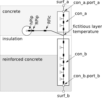
The construction con_a computes transient heat conduction
between the surface heat port surf_a and the
plane that contains the pipes, with the heat port con_a.port_a connecting to surf_a.
Similarly, the construction con_b is between the plane
that contains the pipes and the surface heat port
sur_b, with the heat port con_b.port_b connecting to surf_b.
The temperature of the plane that contains the pipes is computes using a fictitious
resistance RFic, which is computed by
Buildings.Fluid.HeatExchangers.RadiantSlabs.BaseClasses.Functions.AverageResistance.
There is also a resistance for the pipe wall RPip
and a convective heat transfer coefficient between the fluid and the pipe inside wall.
The convective heat transfer coefficient is a function of the mass flow rate and is computed
by
Buildings.Fluid.HeatExchangers.RadiantSlabs.BaseClasses.InternalFlowConvection.
This resistance network is instantiated several times along the flow path. The parameter
nSeg determines how many instances are used. However, all instances
connect to the same surface temperature heat ports surf_a and surf_b.
The material layers are declared by the parameter layers, which is an instance of
Buildings.HeatTransfer.Data.OpaqueConstructions.
The first layer of this material is the one at the heat port surf_a, and the last layer
is at the heat port surf_b.
The parameter iLayPip must be set to the number of the interface in which the pipes
are located. For example, consider the following floor slab.
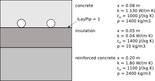
  Buildings.HeatTransfer.Data.OpaqueConstructions.Generic layers(
        nLay=3,
        material={
          Buildings.HeatTransfer.Data.Solids.Generic(
            x=0.08,
            k=1.13,
            c=1000,
            d=1400,
            nSta=5),
          Buildings.HeatTransfer.Data.Solids.Generic(
            x=0.05,
            k=0.04,
            c=1400,
            d=10),
          Buildings.HeatTransfer.Data.Solids.Generic(
            x=0.2,
            k=1.8,
            c=1100,
            d=2400)}) "Material definition for floor construction";
Note that we set nSta=5 in the first material layer. In this example,
this material layer is the concrete layer in which the pipes are embedded. By setting
nSta=5 the simulation is forced to be done with five state variables in this layer.
The default setting would have led to only one state variable in this layer.
Since the pipes are at the interface of the concrete and the insulation,
we set iLayPip=1.
The initialization of the fluid in the pipes and of the slab temperature are independent of each other.
To initialize the medium, the same mechanism is used as for any other fluid
volume, such as
Buildings.Fluid.MixingVolumes.MixingVolume. Specifically,
the parameters
energyDynamics and massDynamics on the
Dynamics tab are used.
Depending on the values of these parameters, the medium is initialized using the values
p_start,
T_start,
X_start and
C_start, provided that the medium model contains
species concentrations X and trace substances C.
To initialize the construction temperatures, the parameters
steadyStateInitial,
T_a_start,
T_b_start and
T_c_start are used.
By default, T_c_start is set to the temperature that leads to steady-state
heat transfer between the surfaces surf_a and surf_b, whose
temperatures are both set to
T_a_start and
T_b_start.
The parameter pipe, which is an instance of the record
Buildings.Fluid.Data.Pipes,
defines the pipe material and geometry.
The parameter disPip declares the spacing between the pipes and
the parameter length, with default length=A/disPip
where A is the slab surface area,
declares the whole length of the pipe circuit.
The parameter sysTyp is used to select the equation that is used to compute
the average temperature in the plane of the pipes.
It needs to be set to the following values:
| sysTyp | System type |
|---|---|
| BaseClasses.Types.SystemType.Floor | Radiant heating or cooling systems with pipes embedded in the concrete slab above the thermal insulation. |
| BaseClasses.Types.SystemType.Ceiling_Wall_or_Capillary | Radiant heating or cooling systems with pipes embedded in the concrete slab in the ceiling, or radiant wall systems. Radiant heating and cooling systems with capillary heat exchanger at the construction surface. |
The analogy with a three-resistance network and the corresponding equation for
Rx is based on a steady-state heat transfer analysis. Therefore, it is
only valid during steady-state.
For a fully dynamic model, a three-dimensional finite element method for the radiant slab would need to be implemented.
To separate the material declaration layers into layers between the pipes
and heat port surf_a, and between the pipes and surf_b, the
vector layers.material[nLay] is partitioned into
layers.material[1:iLayPip] and layers.material[iLayPip+1:nLay].
The respective partitions are then assigned to the models for heat conduction between the
plane with the pipes and the construction surfaces, con_a and con_b.
Extends from Buildings.Fluid.HeatExchangers.RadiantSlabs.BaseClasses.Slab (Base class for radiant slab), Buildings.Fluid.FixedResistances.BaseClasses.Pipe (Model of a pipe with finite volume discretization along the flow path).
| Type | Name | Default | Description |
|---|---|---|---|
| SystemType | sysTyp | Radiant system type | |
| Distance | disPip | Pipe distance [m] | |
| Generic | pipe | Record for pipe geometry and material | |
| replaceable package Medium | PartialMedium | Medium in the component | |
| Integer | nSeg | 10 | Number of volume segments |
| Length | thicknessIns | 0 | Thickness of insulation [m] |
| ThermalConductivity | lambdaIns | 0.04 | Heat conductivity of insulation [W/(m.K)] |
| Length | diameter | pipe.dIn | Pipe diameter (without insulation) [m] |
| Length | length | A/disPip | Length of the pipe [m] |
| Construction | |||
| Generic | layers | Construction definition | |
| Integer | iLayPip | Number of interface layer in which pipes are located | |
| Area | A | Surface area of radiant slab [m2] | |
| Nominal condition | |||
| MassFlowRate | m_flow_nominal | Nominal mass flow rate [kg/s] | |
| Pressure | dp_nominal | Modelica.Fluid.Pipes.BaseCla... | Pressure [Pa] |
| Initialization | |||
| MassFlowRate | m_flow.start | 0 | Mass flow rate from port_a to port_b (m_flow > 0 is design flow direction) [kg/s] |
| Pressure | dp.start | 0 | Pressure difference between port_a and port_b [Pa] |
| Initialization | |||
| Construction | |||
| Boolean | steadyStateInitial | false | =true initializes dT(0)/dt=0, false initializes T(0) at fixed temperature using T_a_start, T_c_start and T_b_start |
| Temperature | T_a_start | 293.15 | Initial temperature at surf_a, used if steadyStateInitial = false [K] |
| Temperature | T_b_start | 293.15 | Initial temperature at surf_b, used if steadyStateInitial = false [K] |
| Temperature | T_c_start | (T_a_start*con_b[1].layers.R... | Initial construction temperature in the layer that contains the pipes, used if steadyStateInitial = false [K] |
| AbsolutePressure | p_start | Medium.p_default | Start value of pressure [Pa] |
| Temperature | T_start | Medium.T_default | Start value of temperature [K] |
| MassFraction | X_start[Medium.nX] | Medium.X_default | Start value of mass fractions m_i/m [kg/kg] |
| ExtraProperty | C_start[Medium.nC] | fill(0, Medium.nC) | Start value of trace substances |
| ExtraProperty | C_nominal[Medium.nC] | fill(1E-2, Medium.nC) | Nominal value of trace substances. (Set to typical order of magnitude.) |
| Dynamics | |||
| Equations | |||
| Dynamics | energyDynamics | Modelica.Fluid.Types.Dynamic... | Formulation of energy balance |
| Dynamics | massDynamics | energyDynamics | Formulation of mass balance |
| Assumptions | |||
| Boolean | allowFlowReversal | system.allowFlowReversal | = true to allow flow reversal, false restricts to design direction (port_a -> port_b) |
| Advanced | |||
| MassFlowRate | m_flow_small | 1E-4*abs(m_flow_nominal) | Small mass flow rate for regularization of zero flow [kg/s] |
| Boolean | homotopyInitialization | true | = true, use homotopy method |
| Diagnostics | |||
| Boolean | show_V_flow | false | = true, if volume flow rate at inflowing port is computed |
| Flow resistance | |||
| Boolean | from_dp | false | = true, use m_flow = f(dp) else dp = f(m_flow) |
| Boolean | linearizeFlowResistance | false | = true, use linear relation between m_flow and dp for any flow rate |
| Real | deltaM | 0.1 | Fraction of nominal flow rate where flow transitions to laminar |
| Real | ReC | 4000 | Reynolds number where transition to turbulent starts |
| Type | Name | Description |
|---|---|---|
| HeatPort_a | surf_a | Heat port at construction surface |
| HeatPort_a | surf_b | Heat port at construction surface |
| FluidPort_a | port_a | Fluid connector a (positive design flow direction is from port_a to port_b) |
| FluidPort_b | port_b | Fluid connector b (positive design flow direction is from port_a to port_b) |
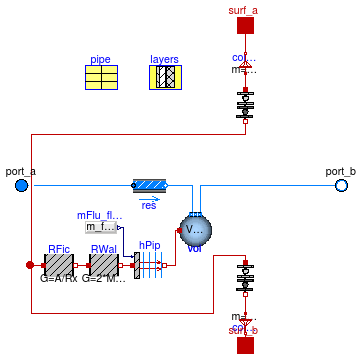
model SingleCircuitSlab "Model of a single circuit of a radiant slab"
  extends Buildings.Fluid.HeatExchangers.RadiantSlabs.BaseClasses.Slab;
  extends Buildings.Fluid.FixedResistances.BaseClasses.Pipe(
     final diameter=pipe.dIn,
     length=A/disPip,
     final thicknessIns=0,
     final lambdaIns = 0.04,
     dp_nominal = Modelica.Fluid.Pipes.BaseClasses.WallFriction.Detailed.pressureLoss_m_flow(
      m_flow=m_flow_nominal,
      rho_a=rho_nominal,
      rho_b=rho_nominal,
      mu_a=mu_nominal,
      mu_b=mu_nominal,
      length=length,
      diameter=pipe.dIn,
      roughness=pipe.roughness,
      m_flow_small=m_flow_small),
      res(dp(nominal=200*length)));
  parameter Modelica.SIunits.Area A "Surface area of radiant slab";
  parameter Modelica.SIunits.Temperature T_c_start=(T_a_start*con_b[1].layers.R+T_b_start*con_a[1].layers.R)/layers.R
    "Initial construction temperature in the layer that contains the pipes, used if steadyStateInitial = false";
  final parameter Modelica.SIunits.Velocity v_nominal = 4*m_flow_nominal/pipe.dIn^2/Modelica.Constants.pi/rho_nominal
    "Velocity at m_flow_nominal";

  Buildings.HeatTransfer.Conduction.MultiLayer con_a[nSeg](
    each final A=A/nSeg,
    each steadyStateInitial=steadyStateInitial,
    each layers(
      final nLay = iLayPip,
      final material={layers.material[i] for i in 1:iLayPip},
      absIR_a=layers.absIR_a,
      absIR_b=layers.absIR_b,
      absSol_a=layers.absSol_a,
      absSol_b=layers.absSol_b,
      roughness_a=layers.roughness_a),
      each T_a_start=T_a_start,
      each T_b_start=T_c_start) "Construction near the surface port surf_a";
  Buildings.HeatTransfer.Conduction.MultiLayer con_b[nSeg](
      each final A=A/nSeg,
      each steadyStateInitial=steadyStateInitial,
      each layers(
      final nLay = layers.nLay-iLayPip,
      final material={layers.material[i] for i in iLayPip + 1:layers.nLay},
      absIR_a=layers.absIR_a,
      absIR_b=layers.absIR_b,
      absSol_a=layers.absSol_a,
      absSol_b=layers.absSol_b,
      roughness_a=layers.roughness_a),
      each T_a_start=T_c_start,
      each T_b_start=T_b_start) "Construction near the surface port surf_b";

protected
  Buildings.Fluid.HeatExchangers.RadiantSlabs.BaseClasses.InternalFlowConvection
    hPip[nSeg](
    each kc_IN_con=
        Modelica.Fluid.Dissipation.HeatTransfer.StraightPipe.kc_overall_IN_con(
        d_hyd=pipe.dIn,
        L=length/nSeg,
        K=pipe.roughness),
    redeclare each final package Medium = Medium,
    each final A=Modelica.Constants.pi*pipe.dIn*length/nSeg)
    "Liquid side convective heat transfer";
  Modelica.Blocks.Sources.RealExpression mFlu_flow[nSeg](each y=m_flow)
    "Input signal for mass flow rate";
  Modelica.Thermal.HeatTransfer.Components.ThermalConductor RWal[nSeg](each G=2*
        Modelica.Constants.pi*pipe.k*(length/nSeg)/Modelica.Math.log(pipe.dOut/pipe.dIn))
    "Thermal conduction through the pipe wall";

  Modelica.Thermal.HeatTransfer.Components.ThermalCollector colAllToOne(
     final m=nSeg) "Connector to assign multiple heat ports to one heat port";
  Modelica.Thermal.HeatTransfer.Components.ThermalCollector colAllToOne1(
     final m=nSeg) "Connector to assign multiple heat ports to one heat port";
 Modelica.Thermal.HeatTransfer.Components.ThermalConductor RFic[nSeg](each G=A/Rx)
    "Average fictitious thermal resistance between pipe surface and plane that contains pipe";


  final parameter Modelica.SIunits.ThermalInsulance Rx=
      Buildings.Fluid.HeatExchangers.RadiantSlabs.BaseClasses.Functions.AverageResistance(
        disPip=disPip,
        dPipOut=pipe.dOut,
        k=layers.material[iLayPip].k,
        sysTyp=sysTyp,
        kIns=layers.material[iLayPip+1].k,
        dIns=layers.material[iLayPip+1].x)
    "Thermal insulance for average temperature in plane with pipes";
equation
  connect(hPip.fluid, vol.heatPort);
  connect(RWal.port_b, hPip.solid);
  connect(RFic.port_b, RWal.port_a);
  connect(colAllToOne1.port_b,surf_a);
  connect(colAllToOne.port_b,surf_b);
  connect(colAllToOne1.port_a, con_a.port_a);
  connect(con_a.port_b, RFic.port_a);
  connect(colAllToOne.port_a, con_b.port_b);
  connect(con_b.port_a, RFic.port_a);

  connect(mFlu_flow.y, hPip.m_flow);
end SingleCircuitSlab;
 Buildings.Fluid.HeatExchangers.RadiantSlabs.ParallelCircuitsSlab
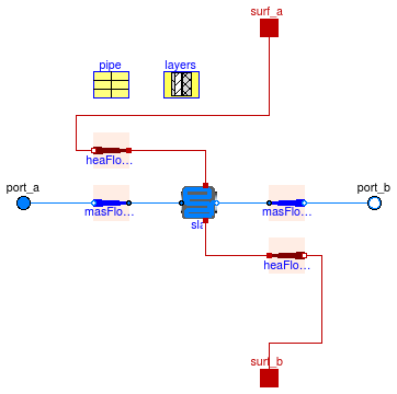
This is a model of a radiant slab with pipes or a capillary heat exchanger embedded in the construction. The model is a composition of multiple models of Buildings.Fluid.HeatExchangers.RadiantSlabs.SingleCircuitSlab that are arranged in a parallel.
The parameter nCir declares the number of parallel flow circuits.
Each circuit will have the same mass flow rate, and it is exposed to the same
port variables for the heat port at the two surfaces, and for the flow inlet and outlet.
A typical model application is as follows: Suppose a large room has a radiant slab with two parallel circuits with the same pipe spacing and pipe length. Then, rather than using two instances of Buildings.Fluid.HeatExchangers.RadiantSlabs.SingleCircuitSlab, this system can be modelled using one instance of this model in order to reduce computing effort. See Buildings.Fluid.HeatExchangers.RadiantSlabs.Examples.SingleCircuitMultipleCircuit for an example that shows that the models give identical results.
Since this model is a parallel arrangment of nCir models of
Buildings.Fluid.HeatExchangers.RadiantSlabs.SingleCircuitSlab,
we refer to
Buildings.Fluid.HeatExchangers.RadiantSlabs.SingleCircuitSlab
for the model documentation.
To allow a better comment for the nominal mass flow rate, i.e., to specify that its value is for all circuits combined, this model does not inherit Buildings.Fluid.Interfaces.PartialTwoPortInterface.
Extends from Modelica.Fluid.Interfaces.PartialTwoPort (Partial component with two ports), Buildings.Fluid.HeatExchangers.RadiantSlabs.BaseClasses.Slab (Base class for radiant slab), Buildings.Fluid.Interfaces.LumpedVolumeDeclarations (Declarations for lumped volumes), Buildings.Fluid.Interfaces.TwoPortFlowResistanceParameters (Parameters for flow resistance for models with two ports).
| Type | Name | Default | Description |
|---|---|---|---|
| replaceable package Medium | PartialMedium | Medium in the component | |
| SystemType | sysTyp | Radiant system type | |
| Distance | disPip | Pipe distance [m] | |
| Generic | pipe | Record for pipe geometry and material | |
| Integer | nCir | 1 | Number of parallel circuits |
| Integer | nSeg | 10 | Number of volume segments in each circuit (along flow path) |
| Length | length | A/disPip/nCir | Length of the pipe of a single circuit [m] |
| Construction | |||
| Generic | layers | Construction definition | |
| Integer | iLayPip | Number of interface layer in which pipes are located | |
| Area | A | Surface area of radiant slab (all circuits combined) [m2] | |
| Nominal condition | |||
| Pressure | dp_nominal | Modelica.Fluid.Pipes.BaseCla... | Pressure [Pa] |
| MassFlowRate | m_flow_nominal | Nominal mass flow rate of all circuits combined [kg/s] | |
| Assumptions | |||
| Boolean | allowFlowReversal | system.allowFlowReversal | = true to allow flow reversal, false restricts to design direction (port_a -> port_b) |
| Initialization | |||
| Construction | |||
| Boolean | steadyStateInitial | false | =true initializes dT(0)/dt=0, false initializes T(0) at fixed temperature using T_a_start, T_c_start and T_b_start |
| Temperature | T_a_start | 293.15 | Initial temperature at surf_a, used if steadyStateInitial = false [K] |
| Temperature | T_b_start | 293.15 | Initial temperature at surf_b, used if steadyStateInitial = false [K] |
| AbsolutePressure | p_start | Medium.p_default | Start value of pressure [Pa] |
| Temperature | T_start | Medium.T_default | Start value of temperature [K] |
| MassFraction | X_start[Medium.nX] | Medium.X_default | Start value of mass fractions m_i/m [kg/kg] |
| ExtraProperty | C_start[Medium.nC] | fill(0, Medium.nC) | Start value of trace substances |
| ExtraProperty | C_nominal[Medium.nC] | fill(1E-2, Medium.nC) | Nominal value of trace substances. (Set to typical order of magnitude.) |
| Dynamics | |||
| Equations | |||
| Dynamics | energyDynamics | Modelica.Fluid.Types.Dynamic... | Formulation of energy balance |
| Dynamics | massDynamics | energyDynamics | Formulation of mass balance |
| Flow resistance | |||
| Boolean | computeFlowResistance | true | =true, compute flow resistance. Set to false to assume no friction |
| Boolean | from_dp | false | = true, use m_flow = f(dp) else dp = f(m_flow) |
| Boolean | linearizeFlowResistance | false | = true, use linear relation between m_flow and dp for any flow rate |
| Real | deltaM | 0.1 | Fraction of nominal flow rate where flow transitions to laminar |
| Advanced | |||
| MassFlowRate | m_flow_small | 1E-4*abs(m_flow_nominal) | Small mass flow rate of all circuits combined for regularization of zero flow [kg/s] |
| Boolean | homotopyInitialization | true | = true, use homotopy method |
| Diagnostics | |||
| Boolean | show_V_flow | false | = true, if volume flow rate at inflowing port is computed |
| Boolean | show_T | false | = true, if actual temperature at port is computed (may lead to events) |
| Type | Name | Description |
|---|---|---|
| HeatPort_a | surf_a | Heat port at construction surface |
| HeatPort_a | surf_b | Heat port at construction surface |
model ParallelCircuitsSlab
  "Model of multiple parallel circuits of a radiant slab"
  extends Modelica.Fluid.Interfaces.PartialTwoPort(
    port_a(p(start=Medium.p_default,
             nominal=Medium.p_default)),
    port_b(p(start=Medium.p_default,
           nominal=Medium.p_default)));
  extends Buildings.Fluid.HeatExchangers.RadiantSlabs.BaseClasses.Slab;
  extends Buildings.Fluid.Interfaces.LumpedVolumeDeclarations;
  extends Buildings.Fluid.Interfaces.TwoPortFlowResistanceParameters(
   dp_nominal = Modelica.Fluid.Pipes.BaseClasses.WallFriction.Detailed.pressureLoss_m_flow(
      m_flow=m_flow_nominal/nCir,
      rho_a=rho_nominal,
      rho_b=rho_nominal,
      mu_a=mu_nominal,
      mu_b=mu_nominal,
      length=length,
      diameter=pipe.dIn,
      roughness=pipe.roughness,
      m_flow_small=m_flow_small/nCir));

  parameter Integer nCir(min=1) = 1 "Number of parallel circuits";
  parameter Integer nSeg(min=2) = 10
    "Number of volume segments in each circuit (along flow path)";

  parameter Modelica.SIunits.Area A
    "Surface area of radiant slab (all circuits combined)";
  parameter Modelica.SIunits.Length length = A/disPip/nCir
    "Length of the pipe of a single circuit";

  parameter Medium.MassFlowRate m_flow_nominal
    "Nominal mass flow rate of all circuits combined";
  parameter Medium.MassFlowRate m_flow_small(min=0) = 1E-4*abs(m_flow_nominal)
    "Small mass flow rate of all circuits combined for regularization of zero flow";

  final parameter Modelica.SIunits.Velocity v_nominal = 4*m_flow_nominal/pipe.dIn^2/Modelica.Constants.pi/rho_nominal/nCir
    "Velocity at m_flow_nominal";

  // Parameters used for the fluid model implementation
  parameter Boolean homotopyInitialization = true "= true, use homotopy method";

  // Diagnostics
   parameter Boolean show_V_flow = false
    "= true, if volume flow rate at inflowing port is computed";
   parameter Boolean show_T = false
    "= true, if actual temperature at port is computed (may lead to events)";

  Modelica.SIunits.VolumeFlowRate V_flow=
      m_flow/Medium.density(sta_a) if show_V_flow
    "Volume flow rate at inflowing port (positive when flow from port_a to port_b)";

  Medium.MassFlowRate m_flow(start=0) = port_a.m_flow
    "Mass flow rate from port_a to port_b (m_flow > 0 is design flow direction) for all circuits combined";
  Modelica.SIunits.Pressure dp(start=0, displayUnit="Pa") = port_a.p - port_b.p
    "Pressure difference between port_a and port_b";

  Medium.ThermodynamicState sta_a=if homotopyInitialization then
      Medium.setState_phX(port_a.p,
                          homotopy(actual=actualStream(port_a.h_outflow),
                                   simplified=inStream(port_a.h_outflow)),
                          homotopy(actual=actualStream(port_a.Xi_outflow),
                                   simplified=inStream(port_a.Xi_outflow)))
    else
      Medium.setState_phX(port_a.p,
                          actualStream(port_a.h_outflow),
                          actualStream(port_a.Xi_outflow)) if
         show_T or show_V_flow "Medium properties in port_a";

  Medium.ThermodynamicState sta_b=if homotopyInitialization then
      Medium.setState_phX(port_b.p,
                          homotopy(actual=actualStream(port_b.h_outflow),
                                   simplified=port_b.h_outflow),
                          homotopy(actual=actualStream(port_b.Xi_outflow),
                            simplified=port_b.Xi_outflow))
    else
      Medium.setState_phX(port_b.p,
                          actualStream(port_b.h_outflow),
                          actualStream(port_b.Xi_outflow)) if
          show_T "Medium properties in port_b";

  Buildings.Fluid.HeatExchangers.RadiantSlabs.SingleCircuitSlab sla(
    redeclare final package Medium = Medium,
    final sysTyp=sysTyp,
    final A=A/nCir,
    final disPip=disPip,
    final pipe=pipe,
    final layers=layers,
    final steadyStateInitial=steadyStateInitial,
    final iLayPip=iLayPip,
    final T_a_start=T_a_start,
    final T_b_start=T_b_start,
    final energyDynamics=energyDynamics,
    final massDynamics=massDynamics,
    final p_start=p_start,
    final T_start=T_start,
    final X_start=X_start,
    final C_start=C_start,
    final C_nominal=C_nominal,
    final allowFlowReversal=allowFlowReversal,
    final m_flow_nominal=m_flow_nominal/nCir,
    final m_flow_small=m_flow_small/nCir,
    final homotopyInitialization=homotopyInitialization,
    final show_V_flow=show_V_flow,
    final from_dp=from_dp,
    final dp_nominal=dp_nominal,
    final linearizeFlowResistance=linearizeFlowResistance,
    final deltaM=deltaM,
    final nSeg=nSeg,
    final length=length,
    final ReC=4000) "Single parallel circuit of the radiant slab";
protected
  parameter Medium.ThermodynamicState state_start = Medium.setState_pTX(
      T=T_start,
      p=p_start,
      X=X_start[1:Medium.nXi]) "Start state";
  parameter Modelica.SIunits.Density rho_nominal = Medium.density(state_start);
  parameter Modelica.SIunits.DynamicViscosity mu_nominal = Medium.dynamicViscosity(state_start)
    "Dynamic viscosity at nominal condition";

  Buildings.Fluid.HeatExchangers.RadiantSlabs.BaseClasses.MassFlowRateMultiplier
                                                                                 masFloMul_a(
      redeclare final package Medium = Medium,
      final k=nCir)
    "Mass flow multiplier, used to avoid having to instanciate multiple slab models";
  Buildings.Fluid.HeatExchangers.RadiantSlabs.BaseClasses.MassFlowRateMultiplier
                                                                                 masFloMul_b(
      redeclare final package Medium = Medium,
      final k=nCir)
    "Mass flow multiplier, used to avoid having to instanciate multiple slab models";
  Buildings.Fluid.HeatExchangers.RadiantSlabs.BaseClasses.HeatFlowRateMultiplier
                                                                                 heaFloMul_a(
      final k=nCir)
    "Heat flow rate multiplier, used to avoid having to instanciate multiple slab models";
  Buildings.Fluid.HeatExchangers.RadiantSlabs.BaseClasses.HeatFlowRateMultiplier
                                                                                 heaFloMul_b(
     final k=nCir)
    "Heat flow rate multiplier, used to avoid having to instanciate multiple slab models";
equation
  connect(sla.port_b, masFloMul_b.port_a);

  connect(masFloMul_b.port_b, port_b);

  connect(port_a, masFloMul_a.port_b);

  connect(masFloMul_a.port_a, sla.port_a);

  connect(sla.surf_a,heaFloMul_a. port_a);
  connect(heaFloMul_a.port_b, surf_a);
  connect(sla.surf_b,heaFloMul_b. port_a);
  connect(heaFloMul_b.port_b, surf_b);
end ParallelCircuitsSlab;